
Related Manuals for MOTU 4pre


Summary of Contents for MOTU 4pre
- Page 1 4pre ™ User Guide for Windows 1280 Massachusetts Avenue Cambridge, MA 02138 Business voice: (617) 576-2760 Business fax: (617) 576-3609 Web site: www.motu.com Tech support: www.motu.com/support...
- Page 2 Authorization Number on the outside of the box below the shipping address. That license agreement is a contract, and clicking “Accept” binds you and MOTU to This warranty does not apply if the equipment has been damaged by accident, all its terms and conditions.
-
Page 3: Table Of Contents
Contents Part 1: Getting Started Quick Reference: 4pre Front Panel Quick Reference: 4pre Rear Panel Quick Reference: MOTU Audio Console About the 4pre Packing List and System Requirements Installing the 4pre Software Installing the 4pre Hardware Part 2: Using the 4pre... - Page 5 Part 1 Getting Started...
-
Page 9: Quick Reference: Motu Audio Console
4pre (or other connected interface). Choose the global sample rate for the system here. Determines the clock source for your 4pre. If you’re just using the analog ins and outs, Choosing a smaller setting here reduces set this to Internal. The other settings are... -
Page 11: About The 4Pre
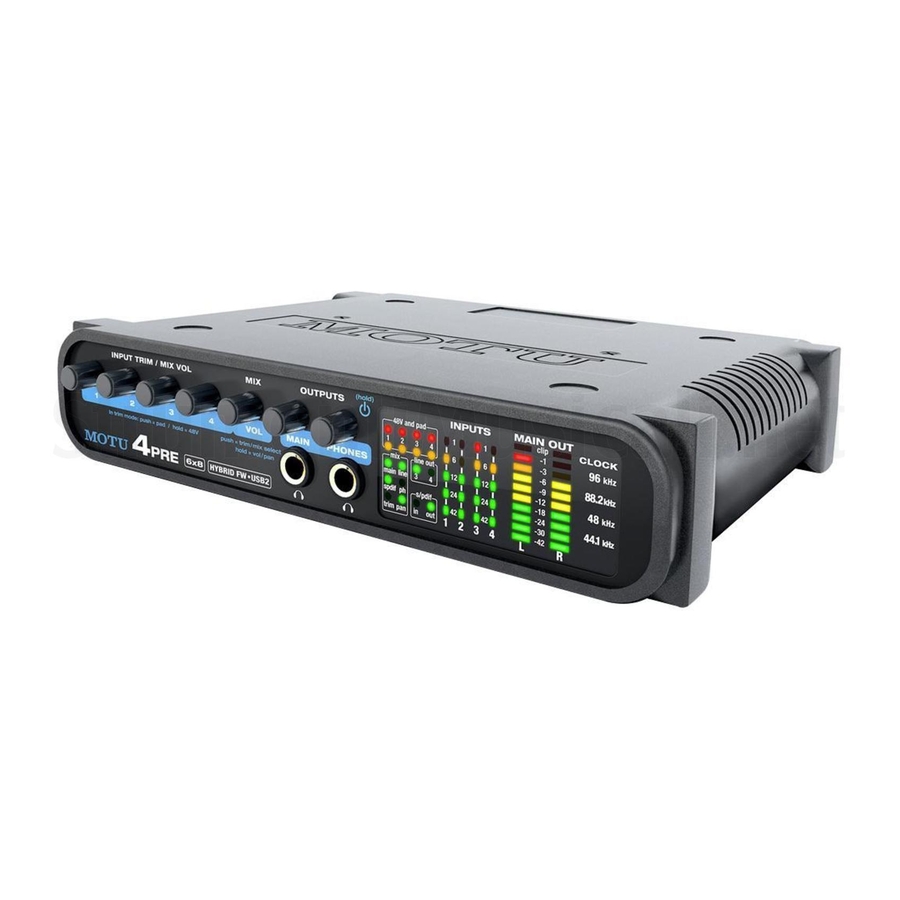
■ The 4pre Rear Panel........11 Front panel volume control of the main outs ■... - Page 12 6 inputs and 8 outputs using front-panel digital rotary encoders or the All 4pre inputs and outputs can be used simulta- CueMix FX control software for Mac and neously, for a total of 6 inputs and 8 outputs: Windows, with 60 dB of adjustment for the mic input and 22 dB for the TRS input.
- Page 13 Power supply record and play back 16-bit or 24-bit audio files at If you do not want the 4pre to draw power from the any supported sample rate via any of the 4pre’s computer, and AC power is available, you can analog or digital inputs and outputs.
- Page 14 CueMix FX provides many advanced features, such CueMix FX gives you complete control over the as an accurate instrument tuner and an extensive 4pre’s CueMix FX on-board mixer, which provides arsenal of audio analysis tools, including a real- no-latency monitoring, mixing of live inputs time FFT, spectrogram “waterfall”...
-
Page 15: Packing List And System Requirements
CHAPTER Requirements PACKING LIST PLEASE REGISTER TODAY! The 4pre ships with the items listed below. If any of Please register your 4pre today. There are two ways these items are not present in your 4pre box when to register. you first open it, please immediately contact your Visit www.motu.com/register... - Page 16 P A C K I N G L I S T A N D S Y S T E M R E Q U I R E M E N T S...
-
Page 17: Installing The 4Pre Software
3 Run the MOTU Audio Installer as instructed in MOTU Audio drivers ....... . . 18 the next section. - Page 18 ASIO is an acronym for Audio Streaming Input and 4pre, such as the clock source and sample rate. For Output. The MOTU Audio ASIO driver provides complete details, see chapter 5, “MOTU Audio multi-channel audio input and output for Console”...
-
Page 19: Installing The 4Pre Hardware
1. Turn on the computer. A typical 4pre setup ....... . . 25 An example setup for computer-based mixing/FX. - Page 20 FireWire plug properly with the notched side available. The port operates at 400 Mbit/s, and it of the FireWire socket on the 4pre. If you attempt to can be connected to any available FireWire port on force the plug into the socket the wrong way, you your computer: Type A (6-pin), Type A “mini”...
- Page 21 INPUT 3 knob the 4pre are switched off. INPUT 4 knob 2 Plug the flat “type A” plug of the 4pre USB cable (included) into a USB2-equipped socket on the When the 4pre switches to FireWire operation, it computer as shown below in Figure 4-1.
- Page 22 +4 dBu line level output signal. The ten-segment MAIN OUT meters provide visual feedback as you turn the knob. The 4pre’s S/PDIF input trims are digitally controlled, so they allow If you make a S/PDIF digital audio connection to you to make fine-tuned adjustments in...
- Page 23 Sync is achieved via the digital I/O connection itself. In this case, you power adapter. The other devices on the chain have to choose S/PDIF as the 4pre’s clock source when resolving it to the other device. should also have their own power supply. In...
- Page 24 PCI FireWire cards — If you plan to connect the DC power supply ■ If you do not want the 4pre to draw power from the 4pre to a PCI card and run the 4pre under bus computer, and AC power is available, you can...
- Page 25 A TYPICAL 4PRE SETUP software, or you can use the 4pre’s CueMix™ no- Here is a typical 4pre studio setup. In this example, latency mixer. You can control the 4pre’s four no external mixer is needed. All mixing and separate mixes from the front panel or from the processing can be done in the computer with audio included CueMix FX software.
- Page 26 4pre Figure 4-5: Connecting multiple MOTU FireWire audio interfaces. Multiple interfaces cannot be bus-powered Do not run the 4pre under bus power when connecting it with other devices to the same FireWire bus. See “Power options” and “Bus power requirements” on page 23.
- Page 27 Adding additional interfaces with a second a second FireWire bus to your computer. It may be FireWire bus possible to add additional MOTU FireWire Third-party FireWire bus expansion products in interfaces connected to such a third-party product, the form of a cardbus (“PC card”) adaptor,...
- Page 28 I N S T A L L I N G T H E 4 P R E H A R D W A R E...
-
Page 29: Part 2: Using The 4Pre
Part 2 Using the 4pre... -
Page 31: Motu Audio Console
‘4pre’ tab settings ........34... -
Page 32: General' Tab Settings
“Connect and sync S/PDIF devices” on page 23. source setting. Figure 5-1: MOTU Audio Console gives you access to all of the settings in the 4pre hardware. M O T U A U D I O C O N S O L E... -
Page 33: Samples Per Buffer
The S/PDIF clock source setting refers to the The delay you hear when routing a live signal ■ S/PDIF coaxial input jack on the 4pre. This setting through your host audio software plug-ins allows the 4pre to slave to another S/PDIF device. -
Page 34: Use Stereo Pairs For Windows Audio
Enable Pedal This setting applies to other MOTU audio Samples Per Buffer will make it a little bit slower, but interfaces, but it does not apply to the 4pre. barely enough to notice. ‘4PRE’ TAB SETTINGS Monitoring live inputs without plug-in effects... -
Page 35: 4Pre Front Panel Operation
PUSH-BUTTON ROTARY ENCODERS it. As you turn the knob, the MAIN OUT ladder All of the knobs on the 4pre front panel are push- LEDs provide visual feedback. button digital rotary encoders. In many cases, you... -
Page 36: Mixing With The Front Panel Controls
Input signals Output signal 4pre mixer Figure 6-2: The 4pre mixer takes all the input signals and combines them to an output. You control the volume of each input separately to produce a good mix. Four separate mixes Figure 6-3: The Mix LEDs indicate which mix you are controlling with the front panel. - Page 37 The trim level adjustment occurs before the signal In balance mode, push To set balance to center enters the 4pre mixer, so it applies to all mixes. Trim is useful for adjusting the overall level of the In width mode, push...
-
Page 38: Visual Feedback When Adjusting Mix Controls
Using the 4pre as a monitor METERING AND ACTIVITY LEDS The Line Out LEDs (Figure 6-3) indicate output mixer in this fashion is a good way to avoid latency (delay) issues that can arise when using audio activity on the quarter-inch Line Out 3-4 jacks. -
Page 39: Preparation
Preparation ......... . 39 Run MOTU Audio Console ......39 Figure 7-1: MOTU Audio Console. -
Page 40: Configuring Host Audio Software
Engine menu. For information about the H/W samplers, microphones, and so on connected to Buffer Size setting, see “Adjusting the audio I/O the analog inputs of the 4pre. If so, you will often be buffer” on page 47. mixing their live input with audio material ☛... - Page 41 Figure 7-3. Activate the inputs and outputs within in Figure 7-5. Cubase or Nuendo as usual. Figure 7-3: Enabling the MOTU Audio ASIO driver in Cubase Live Figure 7-5: Enabling the MOTU Audio ASIO driver in Reason In Ableton Live, access the preferences window and Reaper click the Audio tab.
- Page 42 Figure 7-7: Enabling the MOTU Audio ASIO driver in SONAR. 4 Next, in the Audio preferences section, choose Devices. 5 Check the 4pre inputs and outputs that you wish to use and uncheck the ones you don’t, as shown in Figure 7-8 on page 42.
-
Page 43: Reducing Latency
Figure 7-10: Make sure you have chosen a 4pre input and output for the playback and recording timing master settings. Remember that the headphone output can be 3 Additionally, if you are using the MOTU WDM configured in MOTU Audio Console to mirror... -
Page 44: Processing Live Inputs With Host Plug-Ins
List position you’ll see an 4pre input called Mix1 Return 1-2. Main This is a stereo feed from the 4pre that matches its main outs (Mix 1). This can be used, for example, Line to record a final stereo mix for reference and SPDIF archiving purposes. - Page 45 If you don’t need to process a live input with plug-ins, the easiest way to avoid monitoring latency is to use the 4pre’s CueMix digital mixer to patch the input directly to your monitor outs via the 4pre audio hardware. For details, see “CueMix hardware monitoring”...
-
Page 46: Reducing Monitoring Latency
Figure 8-1: There are two ways to monitor live audio inputs with an 4pre: 1) through the computer or 2) via CueMix hardware monitoring. This diagram shows method 1 (through the computer). When using this method, use your host software’s buffer setting to reduce the slight delay you hear when monitoring the live input, but don’t lower it too much, or your computer might get sluggish. - Page 47 Console, as shown in Figure 8-3 via the Samples Per Buffer setting. Figure 8-3: Lowering the ‘Samples Per Buffer’ setting in MOTU Audio Console reduces patch thru latency. But doing so increases the processing load on your computer, so keep an eye on the Perfor- mance Monitor in your host audio software.
- Page 48 If you reduce the size, you audio inputs are patched directly through to reduce patch thru latency, but significantly increase outputs in the 4pre itself and are mixed with disk the overall processing load on your computer, tracks playing back from your audio software. This...
- Page 49 (without the need to use the separate CueMix FX software). In most cases, this support consists of patching an 4pre input directly to an output when you record- arm a track. Exactly how this is handled depends on the application.
- Page 50 R E D U C I N G M O N I T O R I N G L A T E N C Y...
-
Page 51: Cuemix Fx
4pre’s mixing features. Essentially, it gives you on-screen control of the 4pre’s front panel CueMix has no buffer latency. Thanks to the ■ mixing controls. - Page 52 Scope channels for into mono stereo pairs the Tuner and audio channels analysis tools. Figure 9-1: CueMix FX is a virtual mixer that gives you control over the 4pre’s on-board mixing features. C U E M I X F X...
-
Page 53: Working With A Mix
Click the mix name to edit its text. pad and 48V phantom power settings that you can Master fader also control from the 4pre front panel encoders. The master fader (Figure 9-1) controls the overall There are separate settings for each mic input. -
Page 54: Shortcuts
Note that an input can have to a mic input on your 4pre. For Listenback, set up different level, pan, mute and solo settings for each a dedicated listenback mic in the live room for the mix. - Page 55 engaged. To completely silence all other CueMix Control room audio, turn them all the way down. Attenuation Talkback mic only occurs when talkback or listenback is engaged. Audio playing back from disk (your host software) is not affected. Main Talk / Listen signal routing outs Click the Talk/Listen routing button (Figure 9-3) to open the routing dialog (Figure 9-4).
-
Page 56: Scope Channel Selection
Undo/Redo Saving and loading hardware presets CueMix FX supports multiple undo/redo. This The 4pre can store up to 16 presets in its on-board allows you to step backwards and forwards memory. A preset includes all CueMix FX settings through your actions in the software. -
Page 57: Devices Menu
If you wish to scope audio output, send it to the Below each device are five signal analysis tools: FFT 4pre main outs (Mix 1) and choose one or both of Analysis, Oscilloscope, X-Y Plot, Phase Analysis, the Mix1 returns from the Scope Channel Selection and the Tuner. - Page 58 The Show EQ controls item is for other MOTU value range of the x-axis (frequency). Click and audio interfaces and is grayed out for the 4pre. drag the values up or down to set them, or double- click to return to the default value.
-
Page 59: Oscilloscope
(see “View controls”). and largest displayed amplitude. Opening the oscilloscope Spectrogram controls Each MOTU audio interface has its own The Floor control (Figure 9-5) sets the amplitude oscilloscope. To open an oscilloscope, choose the threshold for the spectrogram display, from -144 Oscilloscope item from the Devices menu under the dB up to 1 dB. - Page 60 View controls Horizontal controls (time axis) The View controls (Figure 9-11) provide several The Horizontal controls (Figure 9-12) configure options for the oscilloscope display. the value range of the x-axis (time). Click and drag the values up or down to set them, or double-click to return to the default value.
- Page 61 Waveform Recognition Trigger indicator The Waveform Recognition option searches Trigger menu through new audio data looking for a waveform Criteria check boxes which most resembles that which was previously displayed. The region where this takes place is a small window around the line marking time equals zero, denoted by the extra vertical graph lines Figure 9-14: Trigger settings surrounding it.
- Page 62 Magnitude is enabled, the trigger will look for both Trigger indicator The Trigger indicator (Figure 9-14 on page 61) +0.500 and -0.500. You will see a second blue line displays the state of the trigger, and also provides a appear in the display when Magnitude is enabled to way to manually interact with it.
- Page 63 To adjust the left and right edges of the Viewing transients such as drum hits If you loop a snare hit or other similar transient measurement area, click and drag the blue bars in audio clip and feed it through the oscilloscope, you the graph, or click and drag the blue numbers in can more or less “freeze”...
- Page 64 If you are building a synth patch on a synthesizer Monitoring control voltage output from Volta (or forming similar highly periodic audio MOTU’s Volta instrument plug-in for Mac OS X material), you can run the audio signal through the turns your audio interface into a control voltage...
-
Page 65: X-Y Plot
(blue) is displayed on the right. This meter Opening the X-Y Plot displays the correlation between the two channels. Each MOTU audio interface has its own X-Y Plot window. Choose the X-Y Plot item from the Devices menu under the desired interface (Figure 9-6 on page 57). - Page 66 Choosing a channel to display Color/Grayscale The X-Y Plot follows the currently chosen Scope In Color mode (Figure 9-18) the most recently channels (Figure 9-1 on page 52). displayed audio data is shown in red, which fades to yellow, green and then finally blue, before View controls disappearing.
- Page 67 Persistence Using the X-Y Plot The Persistence controls (Figure 9-21) affect the The X-Y Plot helps you “see” the width of the stereo appearance of data from when it is first displayed field of a mix. It also helps you determine if a mix until it disappears from the grid.
-
Page 68: Phase Analysis
The correlation meter will remain active while the display is paused. Opening the Phase Analysis Each MOTU audio interface has its own Phase A/B (stereo audio channels) Analysis window. Choose the Phase Analysis item The View section (Figure 9-24) displays the pair of from the Devices menu under the desired interface input or output audio channels you are viewing. - Page 69 Line/Scatter Rectangular/Polar Choose either Line or Scatter from the menu in the Choose either Rectangular or Polar from the menu View section (Figure 9-24) to plot each data point in the View section (Figure 9-24) to control how as either a single pixel or as a continuous line that audio is plotted on the Phase Analysis grid.
- Page 70 Horizontal and vertical controls frequencies, if the distance (phase difference) The Horizontal and Vertical controls (Figure 9-28) between the two frequencies is greater than the let you scale each axis of the grid and offset its zero Max delta theta, then the line is not drawn. point.
- Page 71 outside the critical frequency range of the Checking for phase issues in stereo tracks You can use the Phase Analysis window to check instrument being recorded, you can avoid phase the overall polarity of a stereo mix. Figure 9-31 is problems among the mic signals.
-
Page 72: Tuner
A configuration is just like a hardware preset (a “snapshot” of all settings in CueMix FX and Meter: representation of the pitch difference therefore the 4pre hardware itself), except that it between the detected note and the detected can be created and managed using the CueMix FX fundamental frequency. -
Page 73: Talkback Menu
The Phones menu allows you to choose what you check mark next to it. will hear on the headphone output, just like the Phones setting in MOTU Audio Console. However, Modifying a configuration this menu provides one extra option that is The name of the current configuration is displayed... - Page 74 that is not currently being displayed, CueMix FX Enabled Check this menu item to turn on control surface will jump to the appropriate tab to display the operation of CueMix FX. Uncheck it to turn off control you are adjusting. control surface support.
-
Page 75: Motu Smpte Console
(time code or sample location), separated by a MOTU SMPTE Console ....... 75 forward slash ( / ). -
Page 76: Reader Section
Choose the amount of time READER SECTION you would like the 4pre to freewheel before it gives The Reader section (on the left-hand side of the up and stops altogether. -
Page 77: Generator Section
Turn the level knob to adjust the volume of the “Syncing to SMPTE time code” on page 78. Make SMPTE time code being generated by the 4pre. The sure the Master Clock Source setting in the MOTU level knob disappears when the Destination is set Audio Console window is set to SMPTE. -
Page 78: Syncing To Smpte Time Code
A SMPTE time code source, such as a multitrack tape deck. time code. It can also generate time code, under its ✓ An 4pre by itself, OR with another slaved device (such as a dig- own clock or while slaving to time code. Therefore, ital mixer). -
Page 79: Troubleshooting
This is a common symptom when the problem is the 4pre while recording or playing back audio. that the 4pre is not getting enough power when it is Doing so may cause a brief glitch in the audio. being powered over the Firewire bus. Check the power source for the 4pre. - Page 80 If you have features or ideas you would like to see 4pre unit. You must be able to supply this number implemented, we’d like to hear from you. Please to receive technical support.
- Page 81 Mac OS X FireWire Cubase 14, 31, 39 input and output names 6-pin vs. 4-pin clock source Mackie Control additional busses enabling the 4pre ASIO driver Main outs connecting 20, 21 Mac OS X jacks connector phones volume control PC card adapters...
- Page 82 Mono button 75, 78 Registration Time code sync MOTU Return Assign Tip positive/negative ASIO driver Traveler MOTU Audio Console connecting to 4pre MOTU Audio Setup 9, 17, 31 8, 12 S/PDIF 22, 53 Trim MOTU SMPTE Setup clock source setting Troubleshooting...
Need help?
Do you have a question about the 4pre and is the answer not in the manual?
Questions and answers