
Subscribe to Our Youtube Channel
Related Manuals for MOTU UltraLite-mk4


Summary of Contents for MOTU UltraLite-mk4
- Page 1 UltraLite ™ User Guide Title Page 1280 Massachusetts Avenue Cambridge, MA 02138 Business voice: (617) 576-2760 Business fax: (617) 576-3609 Web site: www.motu.com Tech support: www.motu.com/support...
- Page 2 Unauthorized substitutions may result in fire, electric shock or other hazards. 20.Safety Check - Upon completion of any service or repairs to this MOTU product, ask the service technician to perform safety checks to determine that the product is in safe operating conditions.
-
Page 3: Table Of Contents
Contents Part 1: Getting Started Quick Start Guide UltraLite-mk4 Front Panel UltraLite-mk4 Rear Panel MOTU Pro Audio Control Web App About the UltraLite-mk4 Packing List and System Requirements Software Installation Hardware Installation Part 2: Using the UltraLite-mk4 Presets The Front Panel LCD... - Page 4 Authorization Number on the outside of the box below the shipping address. That license agreement is a contract, and clicking “Accept” binds you and MOTU to This warranty does not apply if the equipment has been damaged by accident, all its terms and conditions.
-
Page 5: Part 1: Getting Started
Part 1 Getting Started... -
Page 7: Quick Start Guide
Application 4 Switch on the UltraLite-mk4. Audio interface Operate as a standard audio interface. 5 Open the MOTU Pro Audio Control web app by Stand-alone mixer Operate as a stand-alone mixer, where all doing one of the following: inputs are mixed to the main outs and mon- itor outs. -
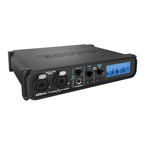
Page 9: Ultralite-Mk4 Front Panel
This setting, along with all front panel settings, can also pad switches for each combo input. The Precision be adjusted from the MOTU Pro Audio Control web app. Digital Trim™ knob provides +60 dB of preamp gain or Push to power on the unit; push and hold for three +30 dB of instrument input gain. -
Page 10: Ultralite-Mk4 Rear Panel
6. These ADAT optical “lightpipe” jacks provide 8 channels of port on the other device. Conversely, connect the UltraLite-mk4’s MIDI IN port to the MIDI OUT port on the To hear audio playback from your host audio software on 24-bit ADAT optical digital I/O at 1x sample rates (44.1 or 48 kHz) and 4 channels at 2x sample rates (88.2 or 96 kHz). -
Page 11: Motu Pro Audio Control Web App
CHAPTER OVERVIEW MAKE HARDWARE AND NETWORK CONNECTIONS MOTU Pro Audio Control is a web app that gives Connect your UltraLite-mk4 to your computer or you complete control over the UltraLite-mk4. laptop with a USB cable. Make sure your iPad, IT’S NOT ON YOUR HARD DRIVE... - Page 12 DEVICE TAB Windows only 1. If you have two or more MOTU inter- 7. Lets you create, save, recall and 11. If an update is available for your 15. (Windows only) Choose the Host faces, the Devices list lets you choose...
- Page 13 20. The digital mixer in the 21. Configure the optical ports for either Device tab settings. UltraLite-mk4 supports up to 48 8-channel ADAT or stereo TOSLink. channels. If you don’t need that At 88.2 or 96 kHz, the ADAT setting 19.
- Page 14 22. In the Computer Setup section, you set to None. Choose the desired clear the password, log in and then are using to view the UltraLite-mk4 can specify how many audio frame format, or use the Enable click Clear Password. If you forget the...
- Page 15 Main Outs on Main Outs (L-R). 5. Locks the grid to prevent accidental the UltraLite-mk4. changes. Unlock to make changes to the grid. M O T U P R O A U D I O C O N T R O L W E B A P P...
-
Page 16: Mixing Tab
13. The Main Mix bus is the master fader 21. Solo and mute. On the Monitor bus, 48-channel mixer in the UltraLite-mk4, and manage entire mixer presets. for the entire mixer. You can add EQ the SC button clears all solos. -
Page 17: Aux Mixing Tab
4. Click the aux bus or group you wish 10. Solo and mute for the aux bus 15. Use the Groups button here to show access to the UltraLite-mk4’s mix busses to view in the window. In this master fader. -
Page 18: Mixer Input Channel Strips
MIXER INPUT CHANNEL STRIPS To access a mixer input channel strip, go to 14. Input level and gain reduction meters for the Mixing tab (page 16), reveal the side bar the compressor. (item #3 on page 16), and then show the 15. -
Page 19: Main Mix And Monitor Channel Strips
For example, if the Main Mix bus is assigned 12. When Follow Solo is enabled, the to the Main Outs on the UltraLite-mk4, Monitor bus switches to the solo bus you’ll see trim settings for the outputs. -
Page 20: Aux Bus Channel Strips
AUX BUS CHANNEL STRIPS Aux busses can be used to create sub-mixes. An aux bus can be assigned to any output in the Routing grid (page 15). To access an Aux bus channel strip, go to the Mixing tab (page 16), reveal the side bar (item #3 on page 16), and then show the aux busses you want in the Mixer Outputs section (28). -
Page 21: Group And Reverb Channel Strips
GROUP AND REVERB CHANNEL STRIPS Group busses can be used to create a mix sub- group, which is a set of inputs you wish to control together as a group. Groups differ from aux busses in that they have aux sends, a reverb send, as well as a main mix send. - Page 22 M O T U P R O A U D I O C O N T R O L W E B A P P...
-
Page 23: About The Ultralite-Mk4
About the UltraLite-mk4 CHAPTER Universal connectivity The UltraLite-mk4 is an 18 x 22 USB audio The UltraLite-mk4 can connect to a computer with interface with console-style 48-channel mixing, high-speed USB 2.0, which is compatible with USB DSP effects, wireless control , and very high quality 3.0. - Page 24 DSP effects from your smart Rack mount or desktop operation phone or tablet — great for live sound mixing from The UltraLite-mk4 is housed in a sturdy, metal- your iPad, tablet, or other wireless device. alloy half-rack enclosure. Rack mounting brackets...
-
Page 25: Packing List And System Requirements
CHAPTER System Requirements PACKING LIST PLEASE REGISTER TODAY! the UltraLite-mk4 ships with the items listed Please register the UltraLite-mk4 today. There are below. If any of these items are not present in the two ways to register. box when you first open it, please immediately Visit www.motu.com/register... - Page 26 P A C K I N G L I S T A N D S Y S T E M R E Q U I R E M E N T S...
-
Page 27: Software Installation
MOTU Discovery app ....... . 28 Download and run the MOTU Pro Audio MOTU Pro Audio WebUI Setup for Windows . -
Page 28: Motu Discovery App
Safety Offset menu (Figure 3-2) also becomes available. This setting allows you to fine tune host Figure 3-1: Choosing the MOTU Pro Audio ASIO driver in Cubase. latency. Larger offsets allow the driver more time to process audio as it transfers to and from the... -
Page 29: Midi I/O On Windows
Figure 3-3: Connecting devices to the UltraLite-mk4. In this example, 1 Make sure your UltraLite-mk4 interface is a controller keyboard is connected to the UltraLite-mk4’s MIDI IN, and a sound module is connected to the UltraLite-mk4 MIDI OUT. connected (a USB connection is required) and turned on. -
Page 30: Audiodesk Workstation Software
MIDI-compatible software. For further information about using the UltraLite-mk4 with host audio software, see “Working with Host Audio Software” on page 45. S O F T W A R E I N S T A L L A T I O N... -
Page 31: Usb Audio Interface Setup
......31 A typical UltraLite-mk4 setup ......32 Audio connections. -
Page 32: Hardware Installation
A TYPICAL ULTRALITE-MK4 SETUP UltraLite-mk4 itself, controlled from your laptop, Here is a typical UltraLite-mk4 setup. All mixing tablet, and smart phone — or several devices and effects processing can be done in the simultaneously. UltraLite-mk4 front panel Headphones Guitar... -
Page 33: Audio Connections
Each mic/guitar input is equipped with a -20 dB Dedicated main outs pad switch, to accommodate input signals that Like all I/O on the UltraLite-mk4, the main could overdrive the input. outputs operate as an independent pair (they don’t share signal with any other output pair). In a Phantom power standard studio configuration, the main outs are... - Page 34 A. Resolve the optical device to the UltraLite-mk4 Figure 4-2: The setup for synchronizing a S/PDIF device with the UltraLite-mk4. Sync is achieved via the digital I/O connection itself. In B. Resolve the UltraLite-mk4 to the optical device this case, you have to choose S/PDIF as the UltraLite-mk4’s clock source when recording from the other device.
-
Page 35: Midi Connections
The UltraLite-mk4 has a MIDI Thru feature for MIDI Device stand-alone operation. This can be enabled from Figure 4-3: Connecting a MIDI device to the UltraLite-mk4. the front panel LCD Settings menu. One-way MIDI connections SYNCING TO SMPTE TIME CODE (LTC) - Page 36 Routing tab. See “LTC-to-MTC conversion” on There are several settings for the time code features page 51 for further info about LTC-to-MTC in your MOTU interface. In the web app, go to the conversion. Device tab (page 14) and scroll to the LTC Setup LTC Format section, shown below.
- Page 37 Part 2 Using the UltraLite-mk4...
-
Page 39: Presets
Create your own presets audio connections to audio gear You can create presets to suit your specific needs. Figure 5-1: Using the UltraLite-mk4 as an audio interface. The UltraLite-mk4 is highly capable and configurable, allowing it to perform many tasks... - Page 40 UltraLite-mk4 Analog outputs Audio inputs from stage, studio, etc. Figure 5-2: Using the UltraLite-mk4 as an audio interface and mixer, simultaneously. Figure 5-3: Use the Optical converter preset to use the UltraLite-mk4 as an optical-to-analog expander for both input and output.
- Page 41 OPTICAL CONVERTER WITH MIXING The Optical converter with mixing preset does not route incoming optical audio directly to the UltraLite-mk4’s analog outputs. Instead, this preset routes the incoming optical audio to the mixer. The mixer then distributes separate mixes to the UltraLite-mk4’s analog output pairs.
- Page 42 P R E S E T S...
-
Page 43: The Front Panel Lcd
The Front Panel LCD CHAPTER OVERVIEW PUSH-BUTTON KNOBS The front panel LCD displays level meters for all The front-panel knobs (Figure 6-2) are push- analog inputs and outputs and activity indicators button digital rotary encoders. Push the knob for for MIDI, optical and S/PDIF I/O. The LCD also the function labeled in blue. - Page 44 See “Optical I/O” on page 34. MIDI Thru When enabled, MIDI data passes directly from the MIDI input to the MIDI output when the UltraLite-mk4 is disconnected from USB (running standalone). LCD Contrast Adjusts the contrast of the LCD. Clear Password Removes password protection in the web app.
- Page 45 If you have devices connected to the optical ports, Choose the MOTU Pro Audio driver....46 see “Choosing a clock source for optical Reducing monitoring latency.
-
Page 46: Working With Host Audio Software
first enters an input Figure 7-1: Choosing the MOTU Pro Audio ASIO driver in Cubase. on the UltraLite-mk4, passes through the interface hardware into the computer, through your host audio software, and then back out to an output. - Page 47 UltraLite-mk4. This is hear when monitoring live inputs through your done by opening the Mix In group in the Outputs audio software: larger buffers produce more delay;...
- Page 48 Figure 7-3: In Cubase or Nuendo, choose Devices menu > Device Setup. Select your interface (UltraLite-mk4), then click the Control through your software. If you reduce the size, you Panel button to access the window above and the Buffer Size setting.
- Page 49 Figure 7-6: An example of routing computer channels (from host audio software) to the analog outputs on a UltraLite-mk4, plus the S/PDIF digital output. Computer channels 1-2 are being split to two pairs of outputs: Phones L-R and Main L-R. The ADAT bank is not being used.
- Page 50 MOTU device. Figure 7-7: An example of routing all eighteen physical inputs on the UltraLite-mk4 to computer channels (for host audio software). W O R K I N G W I T H H O S T A U D I O S O F T W A R E...
- Page 51 For mixer. To route one of these mix buses to your host example, the UltraLite-mk4 can serve as a monitor computer software, click the grid at the mixer, routing channels to musicians, or it can intersection of the mix column and desired serve as an integrated extension of your host’s...
- Page 52 MTC-compatible host software. If your host software requires that you specify the port, you should see your MOTU interface SMPTE Sync port as an available option in the list. In Digital Performer, this is the Sync to...
-
Page 53: High Pass Filter
DSP mixer in LA-2A optical compressor, which provides the UltraLite-mk4. For basic mixer operation, see: vintage, musical automatic gain control Mixing tab ......... . . 16 Reverb . -
Page 54: Mixer Effects
GATE Enabling EQ Each band has an enable/disable button All input channel strips provide a Gate module. (Figure 8-3), allowing you to enable as few or as many bands as needed for the channel strip. Figure 8-2: The Gate module. Enable/disable The gate silences the signal when the input signal’s level drops below the Threshold. -
Page 55: Compressor
COMPRESSOR sculpting. The four-band EQ has been designed to All mixer input channel strips provide a be flexible enough to cover a broad range of applications. By adjusting Gain and Bandwidth compressor module. together, you can emulate the smooth and musical character of classic analog EQ circuits, in which the Gain/Bandwidth dependency was dictated by the actual circuit design and electrical components... - Page 56 RMS mode the signal to 2 dB above the Threshold. When the By default, the compressor operates in Peak mode, input level goes above the threshold, the which uses signal peaks to determine the input attenuation is added gradually to reduce distortion. level.
-
Page 57: Leveler
LEVELER devices are essentially glow-in-the-dark paint on a The Leveler™ (Figure 8-7) provides an accurate piece of foil covered by metalized glass or plastic, model of the legendary Teletronix™ LA-2A® and are the same devices used in low-power night optical compressor, known for its unique and lights. -
Page 58: Reverb
Enabling or disabling the Leveler Routing inputs and groups to the reverb processor The Leveler models the LA-2A so closely, it also The reverb processor is a single, independent unit models the time it takes for an actual LA-2A to that provides stereo reverb. - Page 59 setting represents the bottom frequency of the Mid band. The Ratio determines the length for each band specified in a percentage of the low frequency reverb time. DSP USAGE The DSP Usage meter (item #30 on page 18) shows how much of the available DSP processing power is currently being used by the mixer for the mix and for effects processing.
- Page 60 M I X E R E F F E C T S...
-
Page 61: Motu Audio Tools
Phase Analysis ........73 to work with. Figure 9-1: The MOTU Audio Tools window with the FFT and Spectrogram Analysis . -
Page 62: Analysis Menu
Left Input and Right Input menus. specified, you’ll see 18 channels in the Left/Right Figure 9-2: An example of routing audio sources (listed across the top of the routing grid) on an UltraLite-mk4 interface to computer channels (for routing to the MOTU Audio Tools application). -
Page 63: Fft And Spectrogram Display
FFT AND SPECTROGRAM DISPLAY Pause button The FFT analysis pane displays a real-time Fast View menu Fourier Transform (FFT) frequency measurement Display options and spectrogram “waterfall”, as shown in Figure 9-4. Spectrogram Figure 9-6: FFT view controls. The spectrogram scrolls from top to bottom, where View menu the top edge of the display represents what you are This menu provides various options for displaying... - Page 64 Logarithmic or Linear X-Axis Scale one half of the entire frequency range is displayed. The x-axis defaults to a logarithmic scale, but it can Pos determines which frequency is displayed at the be changed to a linear scale if desired. In the View center of the graph.
-
Page 65: Oscilloscope
OSCILLOSCOPE View menu The View menu (Figure 9-11) lets you choose how The Oscilloscope (Figure 9-10) graphs the to display the audio channel(s) being displayed. amplitude of an audio signal over time. Amplitude is displayed on the y-axis and time is View menu settingWhat it displays displayed on the x-axis. - Page 66 Pausing the display In Zoom/Offset mode, Zoom sets the display zoom The Pause button in the upper right corner of the from 1/2 to 100x, and Pos moves the line marking View section (Figure 9-11) allows you to freeze the amplitude equals zero line up or down.
- Page 67 Enabling the Magnitude checkbox tells the trigger Trigger indicator to look for both positive and negative Level values, Trigger menu regardless of whether the Level value is positive or Criteria check boxes negative. For example, if Level is set to +0.500 and Magnitude is enabled, the trigger will look for both +0.500 and -0.500.
- Page 68 Trigger indicator and the scientific note name. If the measured area is The Trigger indicator (Figure 9-13) displays the long enough, the approximate beats per minute state of the trigger, and also provides a way to (bpm) is displayed. manually interact with it. The Trigger indicator Ideas for using the Oscilloscope always displays one of three colors: The Oscilloscope can be used in many useful ways...
- Page 69 center it in the display. You can also pause the to see if they are inverted from one another or not. The Add and Subtract L - R View menu settings are display at any time and adjust the horizontal bounds to locate a transient.
-
Page 70: X-Y Plot
X-Y PLOT The higher the meter, the higher the correlation The X-Y Plot window (Figure 9-14) graphs the between the two channels. Below are a few amplitude of a stereo audio signal on a two- examples: dimensional grid. Situation Meter level X-Y Plot graph Mathematical relationship For each unit of time (i.e., each sample), the... - Page 71 View controls shown in white and then fades to gray. To adjust the The View controls (Figure 9-15) provide several scale of this color/brightness change, see “Decay” options for the X-Y Plot display. on page 72. Axes Pause button The Axes control (Figure 9-15) sets the opacity of the grid displayed in the graph, from 100% (fully visible) down to 0% (fully hidden).
- Page 72 When warp is positive, they contract towards the origin (center of the grid). When warp is negative, they expand away from the origin. The further the warp value is from zero, the greater the effect. Figure 9-18: The Persistence controls. Using the X-Y Plot The X-Y Plot helps you “see”...
-
Page 73: Phase Analysis
PHASE ANALYSIS View controls The Phase Analysis window (Figure 9-20) graphs The View controls (Figure 9-21) provide several options for the Phase Analysis display. frequency versus phase difference versus amplitude of a stereo signal on either rectangular or polar coordinates. Pause button In rectangular coordinates, the vertical axis represents frequency, and the horizontal axis... - Page 74 Line/Scatter Rectangular/Polar Choose either Line or Scatter from the menu in the Choose either Rectangular or Polar from the menu View section (Figure 9-21) to plot each data point in the View section (Figure 9-21) to control how as either a single pixel or as a continuous line that audio is plotted on the Phase Analysis grid.
- Page 75 Horizontal and vertical controls Max delta theta The Horizontal and Vertical controls (Figure 9-25) Max delta theta (Figure 9-26) only affects Line let you scale each axis of the grid and offset its zero view (see “Line/Scatter” on page 74) and sets the point.
- Page 76 Checking for phase issues in stereo tracks outside the critical frequency range of the You can use the Phase Analysis window to check instrument being recorded, you can avoid phase the overall polarity of a stereo mix. Figure 9-28 is problems among the mic signals.
-
Page 77: Part 3: Appendices
Part 3 Appendices... -
Page 79: Troubleshooting
Set your Clock to use the mixer in the UltraLite-mk4. Please see Source to Internal and try recording just using the “Monitoring through the UltraLite-mk4” on analog inputs and outputs on the UltraLite-mk4. - Page 80 Connecting or powering gear during operation... The serial number of your MOTU device. This is ■ It is not recommended that you connect/ printed on a label placed on the bottom of the rack disconnect, or power on/off devices connected to unit.
-
Page 81: Audio Specifications
Audio Specifications APPENDIX Line Out Connector Type 1/4” Female, TRS Balanced, tip hot Output Impedance 100 ohm Per leg Dynamic Range 117 dB A-weighted THD+N -101 dB -1 dBFS, Unweighted, 1 kHz Frequency Response +0, -0.1 dB, 20 Hz/20 kHz Ref. - Page 82 Phones Connector Type 1/4” Female, TRS Stereo Tip Left, Ring Right Dynamic Range 112 dB A-Weighted THD+N -94 dB Unweighted Frequency Response +0 -0.15 dB, 22 Hz/20 kHz Ref. 1 kHz Drive Max. 80 mw 16/32/55 ohms Trim Range 128 dB 0 to -127 dB (muted) in 1 dB steps S/PDIF Connector Type...
-
Page 83: Mixer Schematics
Mixer Schematics APPENDIX MONO INPUT CHANNEL... - Page 84 STEREO INPUT CHANNEL A P P E N D I X C : M I X E R S C H E M A T I C S...
- Page 85 GROUP BUS A P P E N D I X C : M I X E R S C H E M A T I C S...
- Page 86 MONITOR BUS A P P E N D I X C : M I X E R S C H E M A T I C S...
-
Page 87: Updating Firmware
7 Follow the on-screen instructions. OK to start the update. 5 Follow the on-screen instructions. Figure D-1: The firmware update banner appears automatically at the top of the Device tab when your web host has internet access and MOTU posts an update. - Page 88 Viewing the latest firmware version information You can confirm the firmware version at the bottom of the Device tab (Figure D-2). Figure D-2: The currently installed firmware version is displayed at the bottom of the Device tab. A P P E N D I X D : U P D A T I N G F I R M W A R E...
-
Page 89: Auto-On Mode
6 Carefully replace the top cover of the unit, with manually powered on by pushing and holding the the MOTU logo facing the front of the unit , taking PHONES knob on the front panel (Figure 6-2 on care to make sure that the top edges of the front and page 43). - Page 90 A P P E N D I X E : A U T O - O N M O D E...
-
Page 91: Index
Index 24-bit Safety Offset 12, 28 optical 13, 34 2x SMUX mode connecting ID knob/button 12, 43 12, 13 Device tab Input banks Devices menu Ableton Live 45, 46 Input settings Digital converter (see Optical converter) ADAT optical Inputs 45, 46 Digital Performer connecting optical... - Page 92 Device tab connecting Mixing tab System Information Routing tab System requirements Ratio Pro Audio Installer 7, 11 minimum Compressor MOTU Pro Audio WebUI Setup recommended computer Reaper 45, 46 14, 51 Reason Propellerhead Reason Technical support Reboot 45, 46 Nuendo...
- Page 93 installing drivers View Personal Mix Wave driver WDM (Wave) Driver Width reverb Windows shortcut system requirements WDM (Wave) driver X-Y Plot I N D E X...
- Page 94 I N D E X...
Need help?
Do you have a question about the UltraLite-mk4 and is the answer not in the manual?
Questions and answers