Table of Contents
Advertisement
SPECIFICATIONS ................................................................................................................................................................. 2
NAMES OF PARTS ............................................................................................................................................................... 3
OPERATION MANUAL .......................................................................................................................................................... 5
DISASSEMBLY .................................................................................................................................................................... 10
REMOVING AND REINSTALLING THE MAIN PARTS ....................................................................................................... 11
ADJUSTMENT ...................................................................................................................................................................... 12
NOTES ON SCHEMATIC DIAGRAM .................................................................................................................................. 28
TYPES OF TRANSISTOR AND DIODE .............................................................................................................................. 28
BLOCK DIAGRAM ............................................................................................................................................................... 29
SCHEMATIC DIAGRAM ...................................................................................................................................................... 30
WIRING SIDE OF P.W.BOARD ........................................................................................................................................... 32
VOLTAGE ............................................................................................................................................................................ 36
WAVEFORMS OF MD CIRCUIT ......................................................................................................................................... 37
TROUBLESHOOTING ......................................................................................................................................................... 38
FUNCTION TABLE OF IC .................................................................................................................................................... 41
PARTS GUIDE/EXPLODED VIEW
SERVICE MANUAL
PORTABLE MINIDISC RECORDER
MODEL
CONTENTS
SHARP CORPORATION
MD-MT877/MD-MT877C
MD-MT877(S)
MD-MT877C(S)
• In the interests of user-safety the set should be restored to its
original condition and only parts identical to those specified be
used.
This document has been published to be used
for after sales service only.
The contents are subject to change without notice.
No. S3118MDMT877/
Page
Advertisement
Table of Contents

Related Manuals for Sharp MD-MT877S


Summary of Contents for Sharp MD-MT877S
-
Page 1: Table Of Contents
FUNCTION TABLE OF IC ..............................41 PARTS GUIDE/EXPLODED VIEW PACKING OF THE SET (MD-MT877(S) FOR U.S.A. ONLY) This document has been published to be used SHARP CORPORATION for after sales service only. The contents are subject to change without notice. -
Page 2: Specifications
MD-MT877/MD-MT877C FOR A COMPLETE DESCRIPTION OF THE OPERATION OF THIS UNIT, PLEASE REFER TO THE OPERATION MANUAL. SPECIFICATIONS Power source DC 1.2V: Rechargeable Nickel-Metal Hydride battery (AD-N55BT) x 1 DC 5V: AC adaptor (AC 120V, 60 Hz) DC 1.5V: Commercially available, “AA” size (LR6), alkaline battery x 1 DC 1.5V: Separately available car adaptor, AD-CA55X (for cars with a 12-24V DC negative ground electrical sys- tem) (Used with separately available plug adaptor (AD-M66PA)) Power consumption 7 W (AC adaptor) -
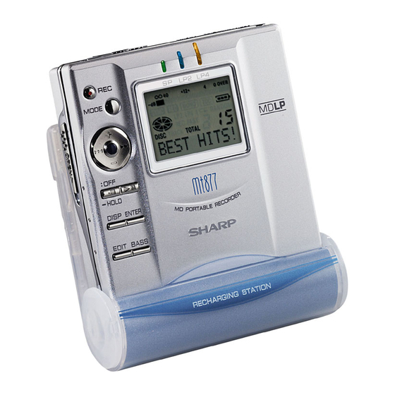
Page 3: Names Of Parts
MD-MT877/MD-MT877C NAMES OF PARTS Main unit 1. Record/Track Mark Button 2. Mode Button 3. Volume/Cursor/Fast Forward/Fast Reverse/ Recording Level/Name Select Button 4. Stop/Power Off/Hold Button 5. Open Lever 6. Display/Character Select Button 7. Edit/Auto Mark/Time Mark Button 8. Play/Pause Button 9. - Page 4 MD-MT877/MD-MT877C Remote control unit 1. Earphones Jack 2. Fast Forward/Fast Reverse Button 3. Display Button 4. Play Mode Button 5. Sound/Track Mark Button 6. Stop/Power Off Button 7. Play/Pause Button 8. Volume Button 9. Hold Switch Remote control display panel 1.
-
Page 5: Operation Manual
MD-MT877/MD-MT877C OPERATION MANUAL Using with the Rechargeable Battery Charging Do not force the When the rechargeable battery is used for the first battery cover time or when you want to use it after a long period of open too far. disuse, be sure to charge it fully. -
Page 6: Error Messages
MD-MT877/MD-MT877C Error Messages ERROR MESSAGES MEANING REMEDY BATT EMPTY The battery is run down. Charge the rechargeable battery or replace the alka- (LoBATT) line battery (or use the AC adaptor for power). BLANK MD Nothing is recorded. Replace the disc with a recorded disc. (BLANK) Can’t COPY You tried to record from a copy prohibited... -
Page 7: Minidisc System Limitations
Troubleshooting Many potential “problems” can be resolved by the owner without calling a service technician. If something seems to be wrong with this product, check the following before calling your authorized SHARP dealer or service center. PROBLEM... - Page 8 MD-MT877/MD-MT877C Insert a MiniDisc Connect the AC adaptor Inserte un minidisco Conecte el adaptador de CA Insert according to the direction of the arrow. Insértelo de acuerdo con la dirección de la flecha. AC 120V, 60 Hz 120V CA, 60Hz RELEASE To an AC outlet A un tomacorriente...
- Page 9 MD-MT877/MD-MT877C Recording Grabación Check that the unit is connected to the stereo system. Compruebe que el aparato esté conectado al sistema estéreo. Press the PAUSE button on the stereo system to enter the play- back pause mode at the point you wish to start recording. Pulse el botón PAUSE del sistema estéreo para entrar en el modo de pausa de reproducción en el punto en el que desee iniciar la grabación.
-
Page 10: Disassembly
MD-MT877/MD-MT877C DISASSEMBLY (B1) x 2 Cares before disassembling Top Cabinet ø 1.4 x 2 mm When assembling the machine after disassembling or (A1) x 2 ø 1.4 x 2 mm repair, observe the following requirements so as to ensure safety and performance. (A1) x 1 1. -
Page 11: Removing And Reinstalling The Main Parts
MD-MT877/MD-MT877C REMOVING AND REINSTALLING THE MAIN PARTS Remove the mechanism according to the disassembling meth- ods 1 to 4. (See Page 10.) How to remove the spindle motor (See Fig. 11-1.) (A2) x 3 1. Remove the solder joints (A1) x 4 of flexible PWB. ø... -
Page 12: Adjustment
MD-MT877/MD-MT877C ADJUSTMENT Test disc MD adjustment needs two types of disc, namely record- ing disc (low reflection disc) and playback-only disc (high reflection disc). Type Test disc Parts No. 1 High reflection disc MMD-110 88GMMD-110 (TEAC Test MD) 2 Low reflection disc MMD-213A 88GMMD-213A (TEAC Test MD) 3 Low reflection disc Recording... - Page 13 MD-MT877/MD-MT877C Operation in each TEST mode 1. AUTO1 Mode 5. TEST-PLAY Mode • When the STOP button is pressed while the AUTO1 menu appears • When the STOP button is pressed while the TEST-PLAY menu or during automatic adjustment, the mode changes to the TEST appears, or in TEST-PLAY or continuous playback mode, the mode mode stop state.
- Page 14 MD-MT877/MD-MT877C 6. TEST-REC Mode 7. NORMAL Mode • When the STOP button is pressed while the TEST-REC menu • When the STOP button is pressed while the NORMAL menu appears, or in the TEST-REC mode or continuous record mode, the appears, the mode changes to the TEST mode stop state.
- Page 15 MD-MT877/MD-MT877C EEPROM (IC402) writing procedure 1. Procedure to replace EEPROM and write initial value of microcomputer in EEPROM (1) Replace EEPROM. (7) Press the "BASS" button, and press 1 time the "FAST (2) Refer to the latest EEPROM data list. REVERSE"...
- Page 16 MD-MT877/MD-MT877C EEPROM DATA LIST (EEPROM version C) Fucus setting Spindle setting Item display Set values Item display Set values FG1 _ SPG _ FG2 _ SPi _ FF0 _ SPm _ FF1 _ SPo _ FF2 _ PGM _ SP1 _ SP2 _ SP3 _ FZH _...
- Page 17 MD-MT877/MD-MT877C Control setting BASS setting Item display Item display Set values Set values CT0 _ B1A _ CT1 _ B1B _ CT2 _ B1C _ CT3 _ B2A _ CT4 _ B2B _ CT5 _ B2C _ CT6 _ B3A _ RC0 _ B3B _ RC1 _...
- Page 18 MD-MT877/MD-MT877C Do the following when replacing the mechanism, the pickup, the EEPROM (IC402), the LSI(IC201) or the main PWB unit. Enter the test mode, move the pickup to the most internal periphery and execute AUTO1. (Use the disc of MMD-213A.) A U T O 1 PLAY A T 1...
- Page 19 MD-MT877/MD-MT877C Change of Tset Mode Menus BASS T E S T : Test mode stop SKIP UP SKIP DOWN Slide external Slide internal periphery move periphery move SKIP DOWN A U T O 1 : Pre-automatic adjustment menu SKIP UP SKIP DOWN A U T O 2 : ATT auto adjustment menu...
- Page 20 MD-MT877/MD-MT877C Servo ATT Auto Adjustment A U T O 2 : ATT auto adjustment menu PLAY A T 2 : During ATT auto adjustment Adjustment error A D J . N G Normal end : ATT adjustment error (adjustment value output) A D J .
- Page 21 MD-MT877/MD-MT877C * In the continuous playback state the number of jump lines changes as follows shown the [BASS] button is pressed. 1 (initial value) BASS BASS 1 0 T R 1 T R 1 0 0 s t p 100s tep BASS * When the [FAST FORWARD] button is pressed in the continued playback mode, jump of specified number of lines occurs in the external periphery direction.
- Page 22 MD-MT877/MD-MT877C Servo Pre-Manual Adjustment M A N U 1 : Pre-Manual Adjustment menu PLAY : Temperature code indication T M P : Temperature code SKIP UP SKIP DOWN : A signal offset (AINO) measurement : Measurement value SKIP UP SKIP DOWN : B signal offset (BINO) measurement : Measurement value SKIP UP...
- Page 23 MD-MT877/MD-MT877C • ABMAXO measurement value : A-ATT (focus) tentative setting : B-ATT (focus) tentative setting DISP DISP : ABMAXO measurement value indication "1" Mark lighting • LPFABO measurement value : A-ATT (focus) tentative setting : B-ATT (focus) tentative setting DISP DISP : LPFABO measurement value indication "1"...
- Page 24 MD-MT877/MD-MT877C : High-reflection pit section B-ATT (focus) setting : Low-reflection pit section B-ATT (focus) setting : Low-reflection groove section B-ATT (focus) setting : ATT setting PLAY P-MODE : Continuous playback (pit section) S Q # # # # : Continuous playback (groove section) A P # # # # # # # # : Address * If the [BASS] button is pressed in the laser ON state (with no disc or the lid open), laser power...
- Page 25 MD-MT877/MD-MT877C Servo Pre-adjustment Value Check R S L T 1 : Pre-adjustment Value Check menu PLAY : A signal offset measurement value (setting) SKIP UP SKIP DOWN : B signal offset measurement value (setting) SKIP UP SKIP DOWN : E signal offset measurement value (setting) SKIP UP SKIP DOWN : F signal offset measurement value (setting)
- Page 26 MD-MT877/MD-MT877C Error History Display • Error history clear D A T A : Error history indication menu DISP After one second C L E A R : Error history clear • Error history indication D A T A : Error history indication menu PLAY : Error history 0 indication E 0 $ $...
- Page 27 MD-MT877/MD-MT877C Test Mode Normal Playback N O R M A L : Test mode normal playback menu PLAY : Normal playback mode @@@@@@ @@@@@@: Mode and address indication * When the [STOP] button is pressed in specific menu, the "TEST MODE STOP" state is set. EEPROM Setting •...
-
Page 28: Notes On Schematic Diagram
MD-MT877/MD-MT877C NOTES ON SCHEMATIC DIAGRAM • Resistor: DESCRIPTION POSITION To differentiate the units of resistors, such symbol as K and REF. NO M are used: the symbol K means 1000 ohm and the symbol SW401 EJECT OFF—ON M means 1000 kohm and the resistor without any symbol is SW901 DISC PROTECT OFF—ON... -
Page 29: Block Diagram
MD-MT877/MD-MT877C J702 MIC IN J703 J703 EARPHONES J701 J701 (READY FOR REMOTE CONTROL TERMINAL OPTICAL IN LINE IN PLUG/IN POWER) TERMINAL 2,5,6,7 Figure 29 BLOCK DIAGRAM – 29 –... -
Page 30: Schematic Diagram
MD-MT877/MD-MT877C C109 MAIN PWB-A C111 C114 R111 C112 TP202 5P(CH) TP139 EFMO PLAYBACK SIGNAL 48 47 46 45 44 43 42 41 40 39 38 37 C131 CK203 RECORD SIGNAL 1234 EFMAGC CK202 CK111 CK112 C132 ADAGI R207 TP204 CK201 R222 0.22 CK113... - Page 31 MD-MT877/MD-MT877C LCD ASS'Y CNA01 7 6 5 4 3 2 1 SWA13 OPEN/CLOSE SWA01 RECORD CA02 SWA02 PLAY SWA03 BASS DADATA RA13 ADDATA RA01 SWA04 EDIT 5.6K DFCK RA14 RA02 SWA05 DISPLAY 8.2K BCLK CN451 RA03 LRCK RA12 SWA06 VOLUME– ADPON OPEN TP451...
-
Page 32: Wiring Side Of P.w.board
MD-MT877/MD-MT877C MAIN PWB-A (TOP VIEW) R251 IC801 Q801 IC251 Q804 Q261 C251 R881 IC202 Q825 Q821 FROM Q254 Q803 R276 IC271 OPTICAL PICKUP R273 R255 Q802 C273 P35 9-G R807 C272 Q806 R254 C274 Q807 R277 R278 R813 R829 Q805 C209 C270 IC431... - Page 33 MD-MT877/MD-MT877C MAIN PWB-A (BOTTOM VIEW) EXTENSION CONTROL EXTENSION BATTERY TERMINAL,- TERMINAL TERMINAL,+ TERMINAL,+ BATTERY TERMINAL,+ TP206 C202 TP804 TP805 L202 R282 R281 TP803 TP200 R151 Q251 Q103 C151 TP801 TP841 L100 TP100 C100 TP109 TP118 TP114 TP113 TP404 Q252 C109 TP122 TP402 TP116...
- Page 34 MD-MT877/MD-MT877C LCD/KEY PWB-B(TOP VIEW) CN451 TO MAIN PWB P32 2-F FLEXIBLE LCD/KEY PWB-B(BOTTOM VIEW) LEDA04 P35 7-H LCD ASS'Y LEDA03 LEDA02 RA12 RA16 CA02 RA05 RA14 RA13 RA06 RA01 RA15 CNA01 RA07 QA01 SWA11 RA08 SWA02 FAST FORWARD PLAY SWA06 SWA13 VOLUME–...
- Page 35 MD-MT877/MD-MT877C M902 TO MAIN PWB CN601 SLED MOTOR P32 2-D MAGNETIC HEAD(3) M903 LIFT MOTOR MECHANISM FLEXIBLE PWB(5) M901 SPINDLE MOTOR LCD ASS'Y(217) OPTICAL PICKUP(4) CN101 TO MAIN PWB P32 2-B CNA01 TO LCD/KEY PWB P34 4-F Figure 35 WIRING SIDE OF P.W.BOARD (4/4) –...
-
Page 36: Voltage
MD-MT877/MD-MT877C VOLTAGE IC501 IC101 IC201 IC401 IC601 IC701 VOLTAGE PIN VOLTAGE PIN VOLTAGE VOLTAGE VOLTAGE VOLTAGE VOLTAGE VOLTAGE 0.79 V 0.26 V 1.24 V – 0.27 V 2.49 V 0.26 V 2.49 V 0.98 V 0.26 V 1.3 V 2.49 V 2.5 V 0.26 V 0.7 V... -
Page 37: Waveforms Of Md Circuit
MD-MT877/MD-MT877C WAVEFORMS OF MD CIRCUIT Stopped 1994 / 12 / 15 22:54:19 Stopped 1994 / 12 / 16 00:24:17 Stopped 1994 / 12 / 16 01:03:40 CH1=2V CH2=2V CH3=2V CH4=2V 50us/div CH1=1mV CH2=500mV CH3=5V CH4=2V 50ms/div CH1=1V CH2=2V CH3=500mV 2ms/div DC 10:1 DC 10:1 DC 10:1... -
Page 38: Troubleshooting
MD-MT877/MD-MT877C TROUBLESHOOTING Use the test mode which indicates trouble causes before repairing the unit. This mode records maximum 2 past error causes as codes. Refer them for repairing. Preparations If dusts and foreign materials are accumulated on the pickup lens, playback sounds can be skipped or the TOC (Table of Contains) can't be displayed. - Page 39 MD-MT877/MD-MT877C • Abnormal display. Is waveform output from CN451 pins 3 to 5 ? Is waveform output from IC401 pins 31 to 33 ? Are the pin 2 (VCC) and pin 12, 13 (GND) normal ? Check the periphery of IC401. Check between IC401 and CN451.
- Page 40 MD-MT877/MD-MT877C • Recording/playback operation. Insert a low reflection disc, and ascertain audio output by normal playback, and then set TEST REC mode. Change MSL from 00H to 80H by the control setting of EEPROM. After completing the operation, return in to 00H. Check voltage of pins 57 and 58 of IC201, pins 2, 3, 6, and 7 of Does the head move down, failing to start record even IC651, pins 4 and 5 of CN601.
-
Page 41: Function Table Of Ic
MD-MT877/MD-MT877C FUNCTION TABLE OF IC IC401 RH-iX0419AWZZ :System Microcomputer (IX0419AW) (1/2) Terminal Name Input/Output Function Pin No. Port Name SYRS Output System LSI register selection output. _SYRD Output System LSI read enable output. _SYWR Output System LSI write enable output. 4-11 PD0-PD7 SYD0-SYD7... - Page 42 MD-MT877/MD-MT877C IC401 RH-iX0419AWZZ :System Microcomputer (IX0419AW) (2/2) Port Name Terminal Name Input/Output Function Pin No. OSC1 OSC1 — Sub clock. _RESET Input Microcomputer hard reset input. DCIN Input DC IN edge detection. STBY _STBY Input Microcomputer standby input (not used). Input Positive power supply.
- Page 43 MD-MT877/MD-MT877C IC201 VHiLR378161-1 :Endec/Servo/Atrac (LR378161) System LSI expansion output port Port Name Terminal Name Input/Output Pin No. Function Remarks EXPORT4 Undecided justice Output Not used Not used EXPORT5 LDCNT1 Output Recording head raising-lowering control output 0. See the separate table *3. EXPORT6 LDCNT2 Output...
- Page 44 MD-MT877/MD-MT877C — M E M O — – 44 –...
- Page 45 “HOW TO ORDER REPLACEMENT PARTS” To have your order filled promptly and correctly, please furnish the For U.S.A. only following information. Contact your nearest SHARP Parts Distributor to order. 1. MODEL NUMBER 2. REF. No. 3. PART NO. 4. DESCRIPTION For location of SHARP Parts Distributor, Please call Toll-Free;...
- Page 46 MD-MT877/MD-MT877C PRICE PRICE PARTS CODE DESCRIPTION PARTS CODE DESCRIPTION RANK RANK COILS INTEGRATED CIRCUITS L100 VPBNN100K0000 AC 10 H IC101 VHIIR3R58M/-1 AM RF Signal Processor,IR3R58M L103 RCILC0353AFZZ AB Tip Solid Induction,100mA IC200 VHI62GR2522-1 AG 2.5V Regulator,62GR2522 IC201 VHILR378161-1 BQ Endec/Servo/Atrac,LR378161 L171 RCILC0356AFZZ AC 10 H...
- Page 47 MD-MT877/MD-MT877C PRICE PRICE DESCRIPTION PARTS CODE PARTS CODE DESCRIPTION RANK RANK C601~604 VCKYCY0JB105K AC 1 F,6.3V R206 VRS-CZ1JB104D AA 100 kohm,1/16W C605 VCKYCZ1AB104K AB 0.1 F,10V R207 VRS-CZ1JB681J AB 680 ohms,1/16W C608 VCKYTV1AB105K AD 1 F,10V R222 VRS-CZ1JB105J AB 1 Mohm,1/16W C652 VCKYCZ1AB104K AB 0.1 F,10V...
- Page 48 MD-MT877/MD-MT877C PRICE PRICE DESCRIPTION PARTS CODE DESCRIPTION PARTS CODE RANK RANK R810 VRS-CZ1JB223J AB 22 kohms,1/16W RCILH0003AWM1 AT Magnetic Head Ass’y R812 VRS-CZ1JB104J AA 100 kohm,1/16W RCTRH8210AFZZ BM Optical Pickup R813 VRS-CZ1JB222J AB 2.2 kohms,1/16W QPWBH0010AWZZ J AH Mechanism Flexible PWB R814 VRS-CZ1JB273J AA 27 kohms,1/16W...
- Page 49 MD-MT877/MD-MT877C PRICE PRICE DESCRIPTION PARTS CODE PARTS CODE DESCRIPTION RANK RANK SPAKZ0630AWZZ Pad,AC Adaptor SPAKZ0692AWZZ AB Sheet,Bubble SSAKA0009AWZZ AA Polyethylene Bag,Battery Charger ACCESSORIES GCASZ0002AWSA J AL Battery Case QCNWG0029AWZZ J Connecting Cord,RCA Type (From Serial No.105 QCNWG0382AFZZ J AK Connecting Cord,RCA Type (To Serial No.104 QCNWG0422AFZZ J AQ Connecting Cord,Optical Type...
- Page 50 MD-MT877/MD-MT877C 501x2 506x3 504x2 M901 M902 M903 Figure 5 MD MECHANISM EXPLODED VIEW – 5 –...
- Page 51 MD-MT877/MD-MT877C MD MECHANISM 603x2 603x2 223x2 212x3 224x2 MAIN PWB 225x4 603x2 239x3 LCD PWB 604x4 Figure 6 CABINET EXPLODED VIEW – 6 –...
- Page 52 MD-MT877/MD-MT877C 22-1 22-7 22-6 22-7 22-3 22-4 22-8 22-5x2 22-2 22-5x2 22-9 Figure 7 BATTERY CHARGER EXPLODED VIEW – 7 –...
-
Page 53: Packing Of The Set (Md-Mt877(S) For U.s.a. Only)
MD-MT877/MD-MT877C PACKING OF THE SET (MD-MT877(S) FOR U.S.A. ONLY) Setting position of switches and knobs Remote Control HOLD CANCEL Operation Manual Connecting Cord, Optical Type Quick Guide Sheet, Bubble Label, Caution Battery Carrying Case SPAKZ0692AWZZ Battery Case Remote Control AC Adaptor Packing Add. - Page 54 MD-MT877/MD-MT877C — M E M O — – 9 –...
- Page 55 MD-MT877/MD-MT877C — M E M O — – 10 –...
- Page 56 MD-MT877/MD-MT877C © COPYRIGHT 2001 BY SHARP CORPORATION ALL RIGHTS RESERVED. No part of this publication may be reproduced, stored in a retrieval system, or transmitted in any form or by any means, electronic, mechanical, photocopying, recording, or otherwise, without prior written permission of the publisher.
Need help?
Do you have a question about the MD-MT877S and is the answer not in the manual?
Questions and answers