Table of Contents
Advertisement
Hydro-Pro Sno-Thro
Owner/Operator Manual
Ръководство за работа на
ползвателя/оператора
Návod k obsluze
Betriebsanleitung
Manual del propietario/operador
Käyttöohjekirja
Manuel du propriétaire/utilisateur
Tulajdonosi/kezelői útmutató
Manuale del proprietario/operatore
Gebruikshandleiding
Brukerhåndbok
Instrukcja obslugi / operatora
Manualul proprietarului /
operatorului
Руководство владельца/
пользователя
Navodila za uporabo
Príručka majiteľa/obsluhy
Instruktionsbok
Kullanım Kılavuzu
®
926325 – Hydro Pro 28 Track
926514 – Hydro Pro 32 Track 12V
E10
Models
926326 – Hydro Pro 28
(SN 95,000 +)
926328 – Hydro Pro 32
(SN 95,000 +)
926329 – Hydro Pro 36
(SN 000101 +)
(SN 000101 +)
(SN 000101 +)
04519715C 6/13
Printed in USA
Advertisement
Table of Contents

Related Manuals for Ariens Hydro Pro Track 32


Summary of Contents for Ariens Hydro Pro Track 32
- Page 1 ® Hydro-Pro Sno-Thro Owner/Operator Manual Models Ръководство за работа на 926326 – Hydro Pro 28 (SN 95,000 +) ползвателя/оператора 926328 – Hydro Pro 32 Návod k obsluze (SN 95,000 +) Betriebsanleitung 926329 – Hydro Pro 36 (SN 000101 +) Manual del propietario/operador 926325 –...
- Page 2 PROIZVAJALEC – ES VYHLÁSENIE O ZHODE, VYDANÉ VÝROBCOM – ÜRETİCİ TARAFINDAN DÜZENLENEN EC UYGUNLUK BEYANI We the undersigned, ARIENS COMPANY, certify that: Ние, долуподписаните от фирма ARIENS, удостоверяваме, че: My, nížepodepsaní, ARIENS COMPANY, prohlašujeme, že: Der Unterzeichnete, ARIENS COMPANY, bescheinigt, dass: Nosotros, los abajo firmantes, ARIENS COMPANY, certificamos que: Allekirjoittanut, ARIENS COMPANY, vakuuttaa, että: Nous, soussignés ARIENS COMPANY, certifions que:Alulírott, ARIENS COMPANY,...
- Page 3 и Гаранция (Пазител на техническото досие) / Päivämäärä – Date – Správce shody výrobku a záruky (správce technické Dátum – Data – Datum – Ariens Company dokumentace) / Director Product Conformance & War- Dato – Data – Data – Brillion, WI 54110-1072 USA ranty (Archivar der technischen Akte) / Director de con- дата...
-
Page 4: Table Of Contents
PRODUCT REGISTRATION Numbers are located on the product The Ariens dealer must register the product registration form in the unit literature at the time of purchase. Registering the package. They are printed on a serial number product helps the company process warranty label, located on the frame of your unit. - Page 5 4. Review recommended lubrication, maintenance and adjustments. 5. Review Limited Warranty Policy. 6. Fill out a Product Registration Card and return the card to the Ariens Company or go to www.ariens.eu. EN - 5...
-
Page 6: Safety
SAFETY PRACTICES AND LAWS WARNING: To avoid injury to hands Practice usual and customary safe working and feet, always disengage precautions, for the benefit of yourself and clutches, shut off engine, and wait others. Understand and follow all safety for all movement to stop before messages. - Page 7 1. DANGER! 2. DANGER! Danger! Danger! ONLY use clean-out tool to clear blockages. NEVER use your hands. ROTATING PARTS! ONLY use clean-out tool to clear blockages. NEVER use Never direct discharge your hands. High speed towards persons or impeller rotates below property that may be discharge opening.
-
Page 8: Safety Rules
Emission controls and components glasses with side shields, and protective can only be adjusted by an Ariens Company gloves. Wear proper footwear to improve dealer or an authorized engine footing on slippery surfaces. - Page 9 Understand: DO NOT park unit on a slope unless absolutely necessary. When parking on a • How to operate all controls. slope always block the wheels. • The functions of all controls. ALWAYS shut off engine, remove key, and • How to STOP in an emergency.
- Page 10 Explosive gases from battery can cause For extended storage, clean unit thoroughly. death or serious injury. Poisonous battery See Engine Manual for proper storage. fluid contains sulfuric acid and its contact with Use only attachments or accessories skin, eyes or clothing can cause severe designed for your unit.
-
Page 11: Assembly
ASSEMBLY IMPORTANT: Be careful not to damage cable WARNING: AVOID INJURY. Read spring hooks when rotating handlebars and understand the entire Safety upward. section before proceeding. 5. Install and tighten all hardware on the handlebar assembly and shift rod. WARNING: Dropping or tipping over boxed unit could result in personal injury or damage to unit. - Page 12 NOTE: Leave discharge chute pedestal loose to help install the chute rod. OS7040 1. Mounting Holes 2. Discharge Chute 3. Discharge Chute Ring 4. Chute Pedestal 5. Mounting Hardware Figure 5 4. Remove the gear cover from top of chute pedestal. 5.
- Page 13 NOTE: If chute does not stay in position, adjust as directed in Discharge Chute Control on page 29, or repair before operation. Remote Deflector Control (Figure 8) Connect the cable end to the cable anchor on the discharge deflector before clipping the cable to the cable bracket on the discharge chute.
-
Page 14: Check Tire Pressure
Check Tire Pressure 4. Adjust clutch idler according to Attachment Clutch/Brake Adjustment on (926326, 328, 329) page 29. Check tire pressure and adjust to the 5. Adjust belt finger, if necessary. See pressure listed on tire sidewall. Check Belt Finger Clearance on page 31. -
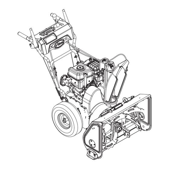
Page 15: Controls And Features
CONTROLS AND FEATURES Figure 9 1. Skid Shoes 11. Chute Rod 2. Clean-Out Tool 12. Handlebar Hardware 3. Remote Discharge Chute Deflector 13. Heated Handles 4. Belt Cover 14. Drift Cutters 5. Headlight 15. Height Adjuster Trigger (926325, 514) 6. Auger 7. - Page 16 17, 18 Figure 10 1. Oil Drain 12. Speed Selector 2. Fuel Shut-Off Valve 13. Traction Drive Clutch Lever 3. Primer Bulb 14. Deflector Remote Control 4. Recoil Starter Handle 15. Chute Control 5. Throttle 16. Muffler Guard 6. Choke Control Knob 17.
-
Page 17: Operation
OPERATION Attachment Clutch – WARNING: AVOID INJURY. Read Right Hand Lever and understand the entire Safety section before proceeding. Squeeze Attachment Clutch Lever against handlebar (1) to WARNING: To avoid injury to hands engage attachment. and feet, always disengage Release both clutch clutches, shut off engine, and wait levers (2) to disengage for all movement to stop before... - Page 18 Speed Selector Snow Clean-Out Tool Position the Speed (Figure 11) Selector in the appropriate position to WARNING: Hand contact with the control forward and rotating impeller is the most reverse travel. common cause of injury associated with snow throwers. Never use your Forward: hand to clean out the discharge (2) Fastest...
-
Page 19: Heated Handles
IMPORTANT: Before starting or operating ensure that the bypass rod is pushed fully into the machine. Failure to close the bypass rod may result in damage to the transmission. Heated Handles Turn the heated handles switch to the ON (1) position to activate. -
Page 20: Filling Fuel Tank
Stored Position Normal Transport Operating Position Deep Cutting OS7111 Figure 15 FILLING FUEL TANK WARNING: AVOID INJURY. Read and understand the entire Safety section before proceeding. OS7110 Figure 14 GASOLINE Track Angle (926325, 514) IMPORTANT: ALWAYS use gasoline that meets the following guidelines: (Figure 15) •... - Page 21 Fuel Shut-Off Valve NOTE: All gasoline is not the same. If the engine experiences starting or performance IMPORTANT: The fuel shut-off valve MUST problems after using a new gasoline, switch be in the closed position prior to transporting to a different fuel provider or fuel brand. the unit.
- Page 22 IMPORTANT: Use an extension cord that is stop before leaving operator’s position. capable of handling current requirements. See your Ariens dealer for recommended STARTING AND SHUT OFF extension cord. 3. Turn discharge chute straight ahead.
- Page 23 TRAVELING NOTE: A warm engine requires less choking than a cold engine. To travel from one work area to another: 5. Set throttle to proper starting position. 1. Set Throttle to Slow or Part-Throttle 6. Turn ignition key to the START position position.
-
Page 24: Maintenance
MAINTENANCE MAINTENANCE SCHEDULE Ariens Dealers will provide any service or adjustments which may be required to keep The chart below shows the recommended your unit operating at peak efficiency. Should maintenance schedule that should be engine service be required, contact an Ariens performed on a regular basis. -
Page 25: Change Engine Oil
NOTE: Inspect seal washer for wear or Adjustment on page 31. rubber deterioration and replace as needed. CHECK CLUTCH CABLE IMPORTANT: Use only Ariens L3 synthetic severe duty gear lube (Part Number ADJUSTMENT 00068800). Use of other lubricants will void Make sure the attachment clutch and traction unit warranty. - Page 26 Shear Bolts on page 27. Apply grease at the grease NOTE: Apply Ariens Hi-Temp Grease or zerks and then turn the auger assemblies on equivalent to the lubrication fittings. See the auger shaft.
- Page 27 Clean Battery (926514) 2. Locate the fuse holder on the wiring harness and remove the fuse. 3. Install a new fuse of the same amp- WARNING: AVOID INJURY. Read rating and type. and understand the entire Safety section before proceeding. IMPORTANT: Battery is maintenance-free.
-
Page 28: Service And Adjustments
WARNING: AVOID INJURY. Read (Figure 20) and understand the entire Safety section before proceeding. IMPORTANT: Use only Ariens OEM shear bolts for replacement. Use of any other type SCRAPER BLADE of shear bolt may result in severe damage to unit. See SERVICE PARTS on page 34. - Page 29 To raise or lower the handlebar: If deflector does not follow full range of travel: 1. Place unit in service position (see 1. Push deflector remote all the way Service Position on page 24). forward. 2. Remove bottom cover. 2. Loosen adjusting nuts on cable support bracket underneath the dash panel 3.
- Page 30 DISCHARGE CHUTE CONTROL (Figure 25) If chute does not stay in position while throwing snow or if chute does not rotate freely, adjust the cable under the gear cover so the chute lock fingers engage or disengage the locking gear. If chute does not stay in position: Loosen the cable by loosening the rear adjustment nut, and then tightening the...
- Page 31 Check Attachment Idler Arm Roller Clearance (Figure 27) NOTE: It will be difficult to check the measurement inside the frame. Use a 12,7 mm minimum spacer as a gauge to check the clearance between the roller and the frame. 1. Place the unit into the service position. Remove the bottom cover.
- Page 32 Check Attachment Brake Check belt finger clearance here. With the (Figure 28) attachment clutch engaged, there should 1. With the clutch lever disengaged, brake be less than 3 mm clearance between the pad must contact attachment belts. With belts and the belt finger. The belt finger clutch lever engaged, brake pad must be should not touch the belts.
-
Page 33: Traction Drive Belt Replacement
7. Remove attachment drive belts from WARNING: AUGER / IMPELLER engine sheave (it may be necessary to MUST STOP within 5 seconds turn engine sheave using recoil starter when attachment clutch lever is handle). released or unit damage or serious IMPORTANT: To avoid bending bottom cover injury may result. - Page 34 HEIGHT ADJUSTER CABLE 5. Replace attachment drive belts (see Install new attachment drive belts on ADJUSTMENT page 32). (926325, 514) TRACK TENSION ADJUSTMENT (Figure 36): (926325, 514) 1. Make sure that height adjustment lock finger is fully engaged. (Figure 32 and 33) 2.
-
Page 35: Storage
Clean unit thoroughly with mild soap and low ACCESSORIES pressure water and lubricate (see MAINTENANCE on page 24). Touch up all See your authorized Ariens dealer to add the additional accessories available to your scratched painted surfaces. Sno-Thro. Remove weight from wheels by putting blocks under frame or axle. -
Page 36: Troubleshooting
TROUBLESHOOTING PROBLEM PROBABLE CAUSE CORRECTION Engine will not 1. Fuel tank is empty. 1. Fill fuel tank (see FILLING FUEL TANK on page 20). crank/start. 2. Fuel shut-off valve closed. 2. Open fuel shut-off valve. 3. Build up of dirt and residue 3. - Page 37 TROUBLESHOOTING PROBLEM PROBABLE CAUSE CORRECTION Unit throws 1. Shear bolts broken. 1. Replace shear bolts (see Shear Bolts on page 27). snow poorly or 2. Attachment clutch/brake 2. Adjust attachment clutch/brake does not throw not adjusted properly. (see Attachment Clutch/Brake snow.
-
Page 38: Specifications
SPECIFICATIONS Model Number 926326 926328 926329 926325 926514 Description Hydro Pro 28 Hydro Pro 32 Hydro Pro 28 Hydro Pro 32 Hydro Pro 36 Track Track Engine Engine Model Briggs & Stratton Polar Force Pro 2100 Gross Torque* – N-m 28,5 *Engine output stated in gross torque per SAE J1940 as rated by engine manufacturer Displacement –... -
Page 39: Warranty
® ® Sno-Thro , Sno-Tek Chore Performing Equipment Limited Warranty Ariens Company (Ariens) warrants to the original purchaser that Ariens, Gravely, Parker, and Countax ® ® brand chore performing equipment (including Sno-Thro and Sno-Tek equipment) purchased on or after 1/1/2013 will be free from defects in material and workmanship for the time period noted in the chart below. -
Page 40: Customer Responsibilities
Register the product immediately at the time of sale. If the dealer does not register the product, the customer must complete the product registration card in the literature package and return it to Ariens Company, or register the unit online at www.ariens.com, www.gravely.com, www.countax.com or www.parkersweeper.com. - Page 41 Exclusions – Items Not Covered by This Warranty • Parts that are not genuine Ariens, Gravely, Parker or Countax service parts are not covered by this warranty and may void the warranty. • Damages resulting from the installation or use of any part, accessory, or attachment which is not approved by the Ariens Company for use with product(s) identified herein are not covered by this warranty.
- Page 42 Ariens 655 West Ryan Street Brillion, WI 54110-1072 920-756-4688 Fax 920-756-2407 www.ariens.eu Protective Floor Mat Protects floor from rust, dirt and snow melt.
Need help?
Do you have a question about the Hydro Pro Track 32 and is the answer not in the manual?
Questions and answers