
Related Manuals for Motorola 549478-001-00 - PowerBroadband EthernetXD M2a WallPlate Switch


Summary of Contents for Motorola 549478-001-00 - PowerBroadband EthernetXD M2a WallPlate Switch
- Page 1 USER GUIDE T3 PowerBroadband Motorola, Inc. 570510-001-00 rev A Page 1 of 50...
- Page 2 This publication and the information herein is furnished AS IS, is subject to change without notice, and should not be construed as a commitment by Motorola. Motorola assumes no responsibility or liability for any errors or inaccuracies, makes no warranty of any kind (expressed, implied, or staory) with respect to this publication, and expressly disclaims any and all warranties of merchantability, fitness for particular purposes, and noninfringement of third-party rights.
- Page 3 Statement of Compliance Motorola/Symbol hereby declares that this device is in compliance with all the applicable Directives, 2004/108/EC and 2006/95/EC. A Declaration of Conformity may be obtained from http://www2.symbol.com/doc/.
- Page 4 Italy requires a user license for outside usage. Statement of Compliance Motorola/Symbol hereby, declares that this device is in compliance with the essential requirements and other relevant provisions of Directive 1999/5/EC. A Declaration of Conformity may be obtained from http://www2.symbol.com/doc/.
- Page 5 Avoid using a telephone (other than a cordless type) during an electrical storm. There may be a remote risk of electric shock from lightning. 3. Do not use the telephone to report a gas leak in the vicinity of the leak. SAVE THESE INSTRUCTIONS Motorola, Inc. 570510-001-00 rev A Page 5 of 50...
- Page 6 Waste Electrical and Electronic Equipment (WEEE) English: For EU Customers: All products at the end of their life must be returned to Motorola for recycling. For information on how to return product, please go to: www.motorola.com/recycling/weee. Bulgarish: За клиенти от ЕС: След края на полезния им живот всички продукти трябва да се връщат на Motorola за...
-
Page 7: Table Of Contents
Configuring a WLAN Global Radio Commands ................29 Per-WLAN Commands................30 Monitor the WLANs and radios ..............30 Access Control Lists (ACLs) RADIUS network authenticated login WallPlate Installation Enable line power..................35 Finish the installation................36 802.1Q VLANs Motorola, Inc. 570510-001-00 rev A Page 7 of 50... - Page 8 Quality of Service (QoS) QoS commands and concepts ..............42 Dynamic packet classification..............44 QoS Example Line Status Appendix A: Pin-out Assignments Appendix B: Hardware Specifications T3 PowerBroadband .................49 m2 WallPlate ...................49 MC-802 Wireless WallPlate ................50 Motorola, Inc. 570510-001-00 rev A Page 8 of 50...
-
Page 9: Commands And Syntax
Commands and Syntax The Motorola T3 PowerBroadband system can be managed via a Command Line Interface, webUI, and SNMP. Commands that apply to remote WallPlates, such as Ethernet port configurations and wireless interface, are all entered on the T3 Switch. -
Page 10: Global Commands
<1-25> is a port range parameter for the wireless radio connected to the DSL line (interface-id) is a description and is not typed Proper command form: interface wireless enable radio5 wifi wlan enable <wlan<1-25>-<1-16>(interface-id)> Motorola, Inc. 570510-001-00 rev A Page 10 of 50... -
Page 11: Interface Range
To enable Eth1 and Eth2 on every WallPlate, type: interface remote enable port(1-25)-(1,2) VLAN commands can also be completed using interface ranges. To add VLAN 100 to Eth1 on every WallPlate, type: vlan membership add 100 interface port(1-25)-1 Motorola, Inc. 570510-001-00 rev A Page 11 of 50... -
Page 12: System Description
The m2 Ethernet WallPlate has two 10/100Mb Ethernet ports, and a pass-through RJ11 phone connector. It is installed at the end-point where Ethernet service is desired. It operates over a standard 2-wire telephone line. Motorola, Inc. 570510-001-00 rev A Page 12 of 50... -
Page 13: Mc-802 Wireless Wallplate
QoS, 4 queues per port Management • Embedded Layer-1 channel for device management from T3 Switch • Layer-3 IP addresses from private pool or public pool • All management centralized on T3 Switch Motorola, Inc. 570510-001-00 rev A Page 13 of 50... - Page 14 Client link rate Client link strength (dBm) Packets tx/rx Authentication status SSID MAC address • WLAN state information Signal strength and MAC of other APs Tx signal strength Packet Tx/Rx statistics Motorola, Inc. 570510-001-00 rev A Page 14 of 50...
-
Page 15: Hardware
12VDC regulated power supply, US. RoHS compliant. Power supplies used during installation for diagnostics. 65103 552306-001-00 12VDC regulated power supply, Euro. ROHS compliant. Power supplies used during installation for diagnostics. 61299 552304-001-00 RJ11 telephone cable, 2m. RoHS compliant Motorola, Inc. 570510-001-00 rev A Page 15 of 50... -
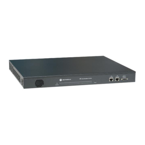
Page 16: T3 Powerbroadband Switch
AC POWER: 100-240VAC IEC320 socket Cross-Connect Connections T3 PowerBroadband Switch Mounting Options T3 ships with mounting ears designed for a standard EIA-19 equipment rack. The ears can be rotated 180 degrees. Motorola, Inc. 570510-001-00 rev A Page 16 of 50... -
Page 17: Mc-802 Wireless Wallplate
Designed to be installed over existing RJ11 wall jack. Bracket has a large opening to route the RJ11 cable from the existing jack. See Installation Chapter for a breakout view of the cover and bracket. Motorola, Inc. 570510-001-00 rev A... - Page 18 DC power connector (used during installation, not under normal operation) RJ11 filtered phone port Eth1 – 10/100 auto-sensing Ethernet Eth2 – 10/100 auto-sensing Ethernet RJ11 line-in port (not shown, accessible when bracket is removed) Motorola, Inc. 570510-001-00 rev A Page 18 of 50...
-
Page 19: System Administration
Destination allows you to copy the running config directly to a remote server. For example; file copy running to tftp://192.168.1.1/my-t3-config.txt At least one (source or destination) must be the local file system. If the source and destination are remote servers, the command will fail. Motorola, Inc. 570510-001-00 rev A Page 19 of 50... -
Page 20: Configuration Files Using The Webui
“admin” password without revealing the password. Contact a Motorola support person for assistance with a setting up secure, staged configurations. To save or load a Configuration file from the webUI, access the System – Configuration screen from the webUI. -
Page 21: Http Menus
Configure WLANs. Create up to 20 profiles. Each profile contains unique parameters Wifi Menu including SSID, DTIM, Broadcast SSID, Isolation, Timeout, and Security Advanced configurations including 802.1Q VLANs, IGMP, QoS Advanced Menu Motorola, Inc. 570510-001-00 rev A Page 21 of 50... -
Page 22: Upgrading The Firmware
NOTE: for information on IP Addressing refer to pages 24-26, “Managing the Wireless WallPlate” Step 3: Reboot the Wireless WallPlate to activate the new software remote image boot port<x> alternate remote reboot port<x> Motorola, Inc. 570510-001-00 rev A Page 22 of 50... -
Page 23: Line Quality
<0.5 to 50> max-threshold <0.5 to 50> Line quality threshold can also be set from the webUI using the Interface DSL menu By default, the thresholds are set to: min-threshold 1.7 bit errors/second max-threshold 2 bit errors/second Motorola, Inc. 570510-001-00 rev A Page 23 of 50... -
Page 24: View System Configuration And Status
Note: When the commit mode is set to manual, the Running config will be different from the Startup config until the changes are committed. Motorola, Inc. 570510-001-00 rev A Page 24 of 50... -
Page 25: Commit Mode
The T3 Command Reference is the master text for all T3 or T3 PowerBroadband configurations. It contains an alphabetical listing of all CLI commands, syntax and example configuration. The web UI features a context-sensitive help system. Motorola, Inc. 570510-001-00 rev A Page 25 of 50... -
Page 26: Managing The Wireless Wallplates
T3 has full access to the Wireless WallPlate. Note this command will not read information from an m2 Ethernet WallPlate. If this command stalls, then the T3 cannot communicate. This is most likely an IP addressing mistake. Motorola, Inc. 570510-001-00 rev A... -
Page 27: Ip Addresses
DHCP server config before the WallPlates link, or else you must disable the DSL ports and re-enable them after the configuration is complete. To disable all DSL ports and remove DHCP address: interface dsl disable port(1-25) Motorola, Inc. 570510-001-00 rev A Page 27 of 50... -
Page 28: Public Ip Address
To view the forwarding bridge table, type “show bridge address” Disable the private IP gateway address: ip private disable Configure the static lease entry: dhcp server disable dhcp server static-lease add <mac address> ip <ip> dhcp server enable Motorola, Inc. 570510-001-00 rev A Page 28 of 50... -
Page 29: Configuring A Wlan
Global WMM parameters for each radio interface wireless mode Set the mode to B, G, or B and G interface wireless name Assign a friendly name to the radio interface wireless country Select the operating country Motorola, Inc. 570510-001-00 rev A Page 29 of 50... -
Page 30: Per-Wlan Commands
WLAN. For example; displays high level status of all active radios show interface wireless status displays detailed status of an individual radio show interface wireless status radio1 Motorola, Inc. 570510-001-00 rev A Page 30 of 50... -
Page 31: Access Control Lists (Acls)
1 permit ip-address 64.174.72.129 mask 255.255.255.128 service telnet ip access-list config 10 deny service all Note: A 32-bit subnet mask will specify one single device with the specified IP address Motorola, Inc. 570510-001-00 rev A Page 31 of 50... -
Page 32: Radius Network Authenticated Login
Practical timeout value is 5 seconds. Retries Number of retries before giving up and trying a different server. A practical entry for retries is 2 to 3. Motorola, Inc. 570510-001-00 rev A Page 32 of 50... -
Page 33: Wallplate Installation
Components provided with the MC-802 WallPlate: 1 – MC-802 WallPlate 1 – RJ11 wall jack mounting adapter 1 – 100mm (4”) RJ11 pigtail cable 2 – 6-32 thread forming Philips head screws, 0.375” Motorola, Inc. 570510-001-00 rev A Page 33 of 50... - Page 34 Regulated 12V power supply. Use of the wrong power supply could result in damage to your WallPlate unit. Please order a small quantity of regulated 12V power supplies from Motorola to use during installation. If you do not have the correct regulated 12V power supply – STOP. Order a regulated 12V power supply from your Motorola PBN sales representative.
-
Page 35: Enable Line Power
T3 Switch to coordinate and enable Line Power. Determine which port is being installed From the CLI, enter this command: Motorola, Inc. 570510-001-00 rev A Page 35 of 50... -
Page 36: Finish The Installation
(enable only the port being installing) Remove the 12V regulated power supply. If the correct port is enabled for line power, the WallPlate will reset and operate from in-line power. Motorola, Inc. 570510-001-00 rev A Page 36 of 50... -
Page 37: 802.1Q Vlans
Untagged packets on any port that is connected to a non-VLAN aware device. For example; if a PC is connected to the WallPlate ports, packets will be untagged. This is similar to the Cisco IOS “access” mode of a switchport. Motorola, Inc. 570510-001-00 rev A Page 37 of 50... -
Page 38: Vlan Commands
Set the mode of operation on the Switch and the WallPlates. Options are IEEE 802.1Q vlan mode tag-based, or Port-based. Note: WallPlates only support tag-based or disabled. CLI command to add ports to a Port-based VLAN. vlan port-group Motorola, Inc. 570510-001-00 rev A Page 38 of 50... -
Page 39: Web Ui Configuration
VLAN Multicast Enable multicast support and assign the VLAN where multicast packets will be sent. This VLAN should be the same as the IGMP VLAN ID for proper delivery of video. Motorola, Inc. 570510-001-00 rev A Page 39 of 50... - Page 40 Note: • Eth1 can communicate with Eth2 • Eth1 can communicate with all DSL ports • Eth2 cannot communicate with all DSL ports • DSL ports cannot communicate with each other Motorola, Inc. 570510-001-00 rev A Page 40 of 50...
- Page 41 Port-based mode on the T3 Switch can be mixed with Tag-based mode on the WallPlate for an effective method to configure VLANs for advanced services. Note VLAN Tutorial One for an example of mixing Port-based and Tag-based VLANs. Motorola, Inc. 570510-001-00 rev A Page 41 of 50...
-
Page 42: Quality Of Service (Qos)
When the mode is set to static, then level applies to all packets received on the port. The four queues are critical, high, medium, and low. network qos classification <method> where method is either 802.1p or tos Motorola, Inc. 570510-001-00 rev A Page 42 of 50... - Page 43 IP TOS bit, and assign the multicast queue to be also use high. T3 has no way to automatically determine where the multicast packets will be transmitted. network qos wred enable | disable Motorola, Inc. 570510-001-00 rev A Page 43 of 50...
-
Page 44: Dynamic Packet Classification
Diffserv byte. This definition is taken from the latest RFC 2475. Note that the IP TOS bits are defined as the three most significant bits of the DiffServ byte. Ethernet frames are mapped to transmission queues based on the following chart: 802.1P bit IP TOS Queue Medium Medium High High Critical Critical Motorola, Inc. 570510-001-00 rev A Page 44 of 50... -
Page 45: Qos Example
Note that the PCs connected to Eth1/Port1-1 will receive 20Mbps bitrate; whereas the other PCs will receive 10Mbps bitrate. While the test is running, change the static level command and watch the behavior change. network qos interface priority eth1 mode static level low Motorola, Inc. 570510-001-00 rev A Page 45 of 50... -
Page 46: Line Status
Distance value shows estimated line length in meters, based on the level of the attenuated Distance (m) signal. Distance is accurate within 10% over 150m. Measurements below 150m are displayed at <150. Motorola, Inc. 570510-001-00 rev A Page 46 of 50... - Page 47 7.45 7.53 7.64 7.71 7.93 8.18 8.47 8.76 9.13 Maximum Power supported for the line 9.45 9.85 10.29 10.76 11.27 11.78 12.36 Out of spec 13.05 13.64 14.40 15.53 16.33 17.49 Motorola, Inc. 570510-001-00 rev A Page 47 of 50...
-
Page 48: Appendix A: Pin-Out Assignments
Appendix A Fast Ethernet WallPlate ports Unused Unused Unused Unused Motorola, Inc. 570510-001-00 rev A Page 48 of 50... -
Page 49: Appendix B: Hardware Specifications
4.75” x 3.5” x 1.25” (120mm x 88mm x 32mm) Weight 0.5lbs (0.2Kg) Environmental Operating Temperature: 0 – 50 degrees Celsius Relative Humidity 5% to 90% NC Compliance FCC Part 15A CE, TUV EN60950, ETSI EN 301 489-1, 17 Motorola, Inc. 570510-001-00 rev A Page 49 of 50... -
Page 50: Mc-802 Wireless Wallplate
Front Panel LEDs 1 x Ready, power status 1 x Status, software booted, errors 1 x Link, xDSL link training 10/100 link status, activity Mounting Options RJ11 wall plate mounting adapter provided Motorola, Inc. 570510-001-00 rev A Page 50 of 50...
Need help?
Do you have a question about the 549478-001-00 - PowerBroadband EthernetXD M2a WallPlate Switch and is the answer not in the manual?
Questions and answers