
Related Manuals for Saunier Duval ISOMAX F 28 E


Summary of Contents for Saunier Duval ISOMAX F 28 E
- Page 1 ISOMAX I N W A R R A N T Y T E C H N I C A L H E L P L I N E 01773 828400 THIS IS A CAT I2E+ APPLIANCE 01773 828100...
-
Page 2: Table Of Contents
The identification plate located on the inside of the appliance certifies the origin where the product was manufactured and the country for which it is intended. If you see any exception to this rule, please contact your nearest Saunier Duval dealer. Thank you in advance for your assistance. -
Page 3: Introduction
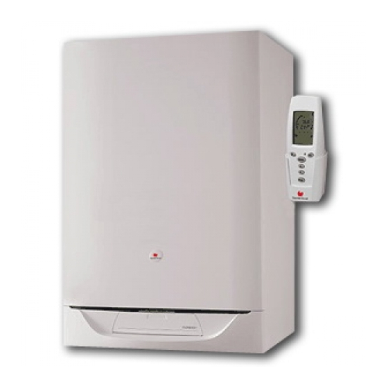
INTRODUCTION The ISOMAX F boiler is a wall mounted modulating The installation must be carried out by a qualified combination boiler with electronic ignition provid- registered person in accordance with the relevant ing central heating and stored hot water. requirements of The Building Regulations, The Wa- ter Byelaws, The Building Standards (Scotland) The boiler is of the I2E+ category for use with Natu- Regulations and any applicable local regulations. -
Page 4: Controls & Lighting
CONTROLS AND LIGHTING Lighting the boiler : Make sure that: The boiler is connected to the electrical supply. The gas service cock is open. Then follow the instructions below : Press the On/Off button (1) The pressure must be between 1 and 2 bar. If not, the system must be filled by a competent person. mode To stop the boiler : Press button (1) Setting to the SUMMER position... -
Page 5: Control Options
CONTROL OPTIONS (a) Programmable room stat Part N 40010, ISOCOM (b) Isocom combined boiler control & programmable room stat part N 85915. Diagram 2 DRAINING Draining and filling Protection against freezing Caution: The boiler is installed as part of a sealed If the boiler is to be out of use for any long periods system which must only be drained and filled by a during severe weather conditions, it is recom-... -
Page 6: Technical Data
TECHNICAL DATA Heating Electrical Heating output ajustable from 10,4 kW Electrical supply 230 V to 27,6 kW Maximum absorbed power 235 W from 35,484 BTU/H Level of protection IP44 to 94,170 BTU/H Efficiency 91 % Maximum heating temperature 87 C Natural Gas (G20) Expansion vessel effective capacity Ø... -
Page 7: Dimensions
DIMENSIONS The ISOMAX is delivered in three separate packages: - the boiler itself - the fixing jig - the flue system Weight: 71 kg Diagram 5 HEATING SYSTEM DESIGN The total volume of water permitted for the heat- The ISOMAX is compatible with any type of ins- ing system depends, amongst other things, on the tallation. -
Page 8: Domestic Hot Water System Design
DOMESTIC HOT WATER SYSTEM DESIGN Copper tubing or plastic Hep 0 may be used for 'Hard Water Areas' the domestic hot water system. Unnecessary In areas where the water is 'hard', more than pressure losses should be avoided. 200mg/litre, it is recommended that a proprietary A flow restrictor limiting the flow through the boiler scale reducer is fitted in the cold water supply to to a maximum of 16 l/min is fitted to the boiler. -
Page 9: Fixing Jig
FIXING JIG The fixing jig is made up, from left to right, as fol- C - Heating flow fitting with isolating valve (q), lows: drain knob (r) and safety valve (10). A - Heating return fitting with isolating valve(v) and D - Domestic hot water outlet fitting with safety drain knob (u). - Page 10 PIPING SYSTEM INSTALLATION Step. 1 To pipe the hot water supply using the mixing valve, The internal safety valves have been tee'd together refer to diagram 8. This shows one outlet supplying and the discharge pipe run so that it exits at the hot water at the boiler hot water "set temperature"...
-
Page 11: Boiler Location
Should any doubt exist as to the permissible posi- Cutting the flue hole tion of the terminal, contact the Saunier Duval Making allowance for the slope of the flue, cut Technical Helpline 01773 828400. hole in external wall, preferably using a core drill. -
Page 12: Boiler Installation
BOILER INSTALLATION Statutory requirements Installing the boiler The installation of this boiler must be carried out by Prior to starting work, the system must be thoroughly a qualified registered person in accordance with flushed using a propriety cleanser such as Sentinel the relevant requirements of the current issue of: X300 to eliminate any foreign matter and contami- The Gas Safety (Installation and Use) Regulations... -
Page 13: Flue Installation
FLUE INSTALLATION Installation of flue assembly Diagram 13 Fit rubber sealing collar (F), see diagram 13, into groove at the outer end of pipe (A). Fit outer pipe (A) into wall with groove to the out- side. Pull pipe inwards to bring rubber sealing collar hard up against external wall, see diagram 14. -
Page 14: Electrical Installation
A suitable room thermostat is available as an ac- cessory, Saunier Duval part number 40011. Please contact your supplier. Also available : For extra control or if the boiler is to be sited in a... -
Page 15: Commissioning
COMMISSIONING The commissioning and first firing of the boiler must Diagram 18 only be done by a qualifed registered person. Gas installation It is recommended that any air is purged from the supply at the gas inlet test point on the gas valve, see diagram 18. - Page 16 COMMISSIONING Bleed each radiator to re- Leave the cap on the Open various hot move the air, re-tighten pump auto air vent open. water taps to bleed bleed screws. system. Make sure the display indicates a system pressure of between 1 and 2 bar. Re-fill system as necessary.
-
Page 17: Lighting The Boiler
COMMISSIONING Lighting the boiler : Make sure that: The boiler is connected to the electrical supply. The gas service cock is open. Then follow the instructions below : Press the On/Off button (1) The pressure must be between 1 and 2 bar. If not, the system must be filled by a competent person. mode To stop the boiler : Press button (1) Setting to the WINTER position... -
Page 18: Safety Devices
COMMISSIONING Setting the heating output Setting the heating output The heating output can be set without the use of a pressure gauge; proceed as follows: Press the display light button and keep pressed for 5 seconds, see diagram 20. Note:The boiler has now been put into 'Service Mode', allowing certain adjustments to be made mode and diagnostic fault codes to be displayed. - Page 19 SAFETY DEVICES No gas supply General safety devices This will be indicated on the display as a Air flow rate safety device pictogram of a spark. If an obstruction, even partial, of the flue occurs, To rectify this, pro- for any reason whatsoever, the built in safety sys- ceed as follows: tem of the boiler will turn the boiler OFF and the fan will continue to run.
-
Page 20: Settings
SETTINGS Gas valve setting MODULATING COIL All boilers are tested and factory set during manu- facture. Should it be necessary to reset a gas valve, for example, after replacement, proceed as fol- lows: Shut down boiler. Minimum setting Remove one electrical connector from the modulating gas valve coil, see diagram 23. -
Page 21: Routine Cleaning And Inspection
ROUTINE CLEANING AND INSPECTION To ensure the continued efficient and safe opera- tion of the boiler it is recommended that it is checked and serviced at regular intervals. The fre- quency of servicing will depend upon the particu- lar installation conditions and usage, but in gen- eral once a year should be enough. -
Page 22: Replacement Of Parts
ROUTINE CLEANING AND INSPECTION Flue system Cold water inlet filter • Check externally to make sure that flue is not Drain down hot water circuit of boiler only, as fol blocked lows: • Inspect flue system to make sure that all fittings •... - Page 23 REPLACEMENT OF PARTS • Open isolating valves on flow and return connec- let pipe to flow sensor and carefully remove from tions, refill, vent and pressurise boiler. sensor. • Check for leaks. • Pull out slotted metal clip securing flow sensor to •...
- Page 24 REPLACEMENT OF PARTS To replace pump pipe from 3-way valve/bypass housing to storage • Drain down heating circuit of the boiler only, as vessel. described previously. • Undo pipe from 3-way valve/bypass housing to Note: It is not necessary to drain down entire heat- fixing jig.
- Page 25 REPLACEMENT OF PARTS • Fit replacement coil in reverse order to removal. • Refit electrical connections in reverse order to re- moval, the polarity of the wires to the modulating coil is not important. To replace central heating safety valve If safety valve seating is damaged, it will be neces- sary to replace safety valve as a complete unit, repair is not possible.
- Page 26 REPLACEMENT OF PARTS • Remove slotted metal clips from heat exchanger con- To replace combustion chamber insulation nection pipes. • Remove combustion chamber cover as de- • Undo nut securing pipe from heat exchanger to 3- scribed in ‘Routine Cleaning and Inspection’. way valve/bypass housing.
-
Page 27: Boiler Schematic
BOILER SCHEMATIC 19 - Heating expansion vessel 1 - Domestic thermistor 20 - Heating thermistor 2 - Three way valve 21 - Overheat safety thermostat 3 - Gas valve 22 - Flame sensor electrode 4 - Gas valve ignition module 23 - Fan 5 - Temperatur sensor for accumulation vessel 24 - Domestic safety valve (6 bar) -
Page 28: Technical Data
TECHNICAL DATA Heating Natural Gas (G20) Heating output ajustable from 10,1 kW Ø Burner injector 1,20 mm to 27,6 kW Inlet pressure 20 mbar from 35,484 BTU/H Maxi. Burner pressure 13,8 mbar to 94,170 BTU/H Mini. Burner pressure 2,16 mbar Efficiency 91 % Gas rate maximum... -
Page 29: Schematic Wiring Diagram
SCHEMATIC WIRING DIAGRAM B8.1 B6.1 B8.2 B6.3 B6.4 B3.3 B6.2 B1.2 B2.9 Opt. H6.1 B2.8 H6.2 B2.11 B1.13 B2.4 B1.15 h8.1 B1.7 h8.2 h4.1 B1.8 B1.10 h4.3 B3.1 h3.1 B3.2 h3.3 B3.3 B3.4 h1.1 B2.6 B2.5 h1.2 CTN 3 h2.4 B1.5 h2.2 B1.6... -
Page 30: Fault Finding
FAULT FINDING Before trying to operate the boiler make sure that : Should there be any doubt about the voltage sup- • All gas supply cocks are open and that the gas ply to any of the components, it is possible to carry supply has been purged of air. - Page 31 FAULT FINDING List of fault codes Code Fault Additional display information No fault Air flow fault Ignition fault -flame detection Overheating Central heating thermistor/wiring fault Domestic hot water thermistor/wiring fault Storage vessel thermistor/wiring fault System pressure sensor fault Fan fault Pump blockage User interface fault Main PCB fault...
-
Page 32: Spare Parts
FAULT FINDING Thermistor values System pressure sensor The following table applies to the central heating, The resistance of the sensor at various pressures is domestic hot water and storage vessel thermistors: as follows : Temperature ( C) Resistance ( ) 0 bar ......
Need help?
Do you have a question about the ISOMAX F 28 E and is the answer not in the manual?
Questions and answers