Table of Contents
Advertisement
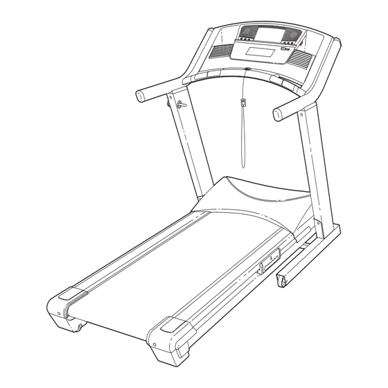
Model No. NETL82406.0
Serial No.
USER'S MANUAL
Write the serial number in the space
above for future reference.
Serial Number Decal
QUESTIONS?
As a manufacturer, we are com-
mitted to providing complete
customer satisfaction. If you
have questions, or if there are
missing or damaged parts,
please call:
08457 089 009
or write:
ICON Health & Fitness, Ltd.
Customer Service Department
Unit 4
Revie Road Industrial Estate
Revie Road
Beeston
Leeds, LS118JG
UK
email: csuk@iconeurope.com
CAUTION
Read all precautions and instruc-
tions in this manual before using
this equipment. Save this man-
ual for future reference.
Advertisement
Table of Contents

Related Manuals for NordicTrack Ex3600 Treadmill


Summary of Contents for NordicTrack Ex3600 Treadmill
- Page 1 Model No. NETL82406.0 Serial No. USER'S MANUAL Write the serial number in the space above for future reference. Serial Number Decal QUESTIONS? As a manufacturer, we are com- mitted to providing complete customer satisfaction. If you have questions, or if there are missing or damaged parts, please call: 08457 089 009...
-
Page 2: Table Of Contents
HOW TO ORDER REPLACEMENT PARTS ..........Back Cover Note: An EXPLODED DRAWING is attached in the center of this manual. NordicTrack is a registered trademark of ICON IP, Inc. -
Page 3: Important Precautions
IMPORTANT PRECAUTIONS WARNING: To reduce the risk of burns, fire, electric shock, or injury to persons, read the following important precautions and information before operating the treadmill. 1. It is the responsibility of the owner to ensure 12. Never move the walking belt whilst the power that all users of this treadmill are adequately is turned off. - Page 4 21. When using iFIT cards, an tone will alert you connection to grounding electrodes, and re- when the speed and/or incline of the treadmill quirements for the grounding electrode. is about to change. Always listen for the tone and be prepared for speed and/or incline 29.
- Page 5 Power Lines Ground Standoff Clamp Insulators Service Entrance Mast To External Antenna Conductors Terminal of Treadmill Antenna Lead-in Wire Service Entrance Ground Antenna Equipment Wire Discharge Unit Ground Wire Power Service Grounding Ground Ground Electrode System (e.g. Bonding Clamps Clamps Jumper Interior Metal Water Pipe) Optional Antenna Grounding Electrode Driven 8...
-
Page 6: Before You Begin
BEFORE YOU BEGIN Thank you for selecting the revolutionary NordicTrack ® see the front cover of this manual. To help us assist EX 3600 treadmill. The EX 3600 treadmill offers an im- you, please note the product model number and serial pressive selection of features designed to make your number before calling. -
Page 7: Assembly
76)–4 1” Tek Screw (82)–4 ASSEMBLY 1/2” Screw (10)–3 3/4” Tek Screw (58)–8 t (77)–2 Assembly requires two persons. Set the treadmill in a cleared area and remove all packing materials. Do not dispose of the packing materials until assembly is completed. Note: The underside of the treadmill walking belt is coated with high-performance lubricant. - Page 8 2. Insert the Right Upright (74) into the indicated bracket on the Base (83); be careful not to dislodge the Cage Nuts (76 [see the inset drawing]) from the Right Upright; in addition, be careful not to pinch the Upright Wire (75). Finger tighten three Upright Bolts (72) with three Washers (78) and three Upright Star Washers (71) into the bracket and the Right Upright.
- Page 9 5. Remove the Spring Pin (102) from the lower end of the Gas Spring (88). Next, press the lower end of the Gas Spring (88) onto the ball on the bracket on the Base (83). If necessary, pivot the Frame (48) slightly and rotate the Gas Spring to align the end of the Gas Spring with the ball on the bracket.
- Page 10 8. Press the Latch Sleeve (96) into the Left Upright (73). If necessary, use a rubber mallet to fully insert the Sleeve. Knob Remove the knob from the pin. Make sure that the collar and the spring are on the pin. Next, insert the pin into the Latch Sleeve (96) and the Left Upright (73), and tighten the knob back onto the pin.
- Page 11 Before the personal television can be used, you must connect an antenna, a 75 ohm CATV cable, or a VCR to the 75 ohm antenna terminal on the treadmill frame. Note: No antenna, cable, or adapter is included. HOW TO CONNECT AN ANTENNA 300 Ohm Flat Wire Indoor Antenna 1.
-
Page 12: How To Use The Chest Pulse Sensor
HOW TO USE THE CHEST PULSE SENSOR HOW TO PUT ON THE CHEST PULSE SENSOR each use, it may remain activated longer than nec- essary, draining the battery prematurely. The chest pulse sensor consists of two components: • Store the chest pulse sensor in a warm, dry place. the chest strap and the sensor unit (see the drawing Do not store the chest pulse sensor in a plastic bag below). -
Page 13: Operation And Adjustment
OPERATION AND ADJUSTMENT THE PRE-LUBRICATED WALKING BELT Your treadmill features a walking belt coated with high-performance lubricant. IMPORTANT: Never apply sili- cone spray or other substances to the walking belt or the walking platform. Such substances will deterio- rate the walking belt and cause excessive wear. HOW TO PLUG IN THE POWER CORD This product must be earthed. - Page 14 Clip FEATURES OF THE CONSOLE the treadmill while the voice of a personal trainer coaches you and motivates you through every step of The treadmill console offers an impressive array of your workout. One iFIT Card with three new programs features designed to make your workouts more effec- is included.
- Page 15 When the Users button is pressed, the words HOW TO TURN ON THE POWER “User 1 Selected” or “User 2 Selected” will appear in the display. To identify yourself as User 1 or User 2, press the Users button once or twice. Plug in the power cord (see page 13).
- Page 16 When the settings mode is selected, the display to purchase more iFIT Cards if INSTRUCTION is will show the word ENGLISH or METRIC to indi- selected as your audio setting. If you select the cate which system of measurement is selected. To ON setting, a personal trainer will simply guide change the system of measurement, first highlight you through your iFIT workouts.
- Page 17 Change the incline of the treadmill as desired. HOW TO USE THE MANUAL MODE To change the incline of the treadmill, press one of the twelve Zip-Incline buttons. Each time one of Insert the key into the console. the buttons is pressed, the incline will gradually in- crease until it reaches the selected incline setting.
- Page 18 When the manual mode is selected, the console To use the offers eight display modes. The display mode that handgrip you select will determine which workout informa- pulse sensor, tion is shown. For example, the first display mode first remove shows only the elapsed time and the distance that the sheets of you have walked or run.
- Page 19 If the first or second display mode is selected, a HOW TO USE A CARDIO PROGRAM profile of the speed settings of the program will ap- pear in the display. A small arrow below the profile Insert the key into the console. will indicate your progress.
- Page 20 If the speed or incline setting for the current seg- ment is too high or too low, you can override the setting by pressing the Speed or Incline buttons; however, when the next segment begins, the treadmill will automatically adjust to the speed and incline settings for the next segment.
- Page 21 Measure your heart rate if desired. HOW TO USE A DISTANCE PROGRAM See step 7 on page 18. Insert the key into the console. Turn on the fans if desired. See HOW TO TURN ON THE POWER on page See step 8 on page 18. When you are finished exercising, remove the Personalize console settings if desired.
- Page 22 When a Record program is selected, the display Select a display mode and program the will show the name of the program, the maximum desired speed and incline settings. incline setting of the program, and the maximum When a Record program is selected, the console speed setting.
- Page 23 segment. Note: The same target heart rate setting HOW TO USE A PULSE PROGRAM may be programmed for two or more consecutive segments. CAUTION: Adjust the maximum target heart rate setting if If you have heart prob- desired. lems, or if you are over 60 years of age and have been inactive, do not use the Pulse pro- To adjust the maximum target heart rate setting, grams.
- Page 24 If the speed or incline setting for the current seg- button. If the second Pulse program is selected, ment is too high or too low, you can override the the program will continue until the small arrow setting by pressing the Speed or Incline buttons; reaches the right end of the profile.
- Page 25 Press the Start button to start the program. HOW TO USE AN IFIT CARD A moment after the button is pressed, the tread- Insert the key into the console. mill will automatically adjust to the first speed and incline settings of the program. Hold the handrails See HOW TO TURN ON THE POWER on page and begin walking.
- Page 26 HOW TO OPERATE THE PERSONAL TELEVISION HOW TO USE THE TV SETTINGS MODE The console features a TV settings mode that allows IMPORTANT: Before operating the television, you you to adjust the settings of the television and to save must connect an antenna, a 75 ohm CATV cable, or channels into the television’s memory.
- Page 27 HOW TO ADJUST THE CUSHIONING SYSTEM Press the Power button again and select a video broadcast system for all channels. The treadmill features a cushioning system that re- duces the impact as you walk or run on the treadmill. To select a video broadcast system for all chan- To increase the firmness of the walking platform, step nels, press the Volume buttons until the desired off the treadmill and slide the cushion adjusters toward...
-
Page 28: How To Fold And Move The Treadmill
HOW TO FOLD AND MOVE THE TREADMILL HOW TO FOLD THE TREADMILL FOR STORAGE Before folding the treadmill, adjust the incline to the lowest position. If this is not done, the treadmill may be permanently damaged. Next, unplug the power cord. CAUTION: You must be able to safely lift 45 pounds (20 kg) to raise, lower, or move the treadmill. - Page 29 HOW TO LOWER THE TREADMILL FOR USE 1. Hold the upper end of the treadmill with your right hand as shown. Using your left hand, pull the latch knob to the left and hold it. Pivot the frame down until it is past the latch pin.
-
Page 30: Troubleshooting
TROUBLESHOOTING Most treadmill problems can be solved by following the steps below. Find the symptom that applies, and follow the steps listed. If further assistance is needed, please see the front cover of this manual. PROBLEM: The power does not turn on SOLUTION: a. - Page 31 Next, locate the Reed Switch (14) and the Magnet (12) on the left side of the Pulley (11). Turn the Pulley until the Magnet is aligned with the Reed Switch. Make sure that the gap between the Magnet and the Reed Switch is about about 3 mm (1/8 in.) .
- Page 32 PROBLEM: The incline of the treadmill does not change correctly SOLUTION: a. With the key in the console, press one of the Incline buttons. While the incline is changing, re- move the key. After a few seconds, re-insert the key. The treadmill will automatically rise to the maximum incline level and then return to the minimum level.
-
Page 33: Exercise Guidelines
EXERCISE GUIDELINES begin to use stored fat calories for energy. If your goal WARNING: is to burn fat, adjust the speed or incline of the tread- Before beginning this mill until your heart rate is near the lowest number in or any exercise program, consult your physi- your training zone. -
Page 34: Part List
PART LIST—Model No. NETL82406.0 R0706A To locate the parts listed below, see the EXPLODED DRAWING attached in the center of this manual. Key No. Qty. Description Key No. Qty. Description Foot Rail Cover Right Rear Foot Foot Rail Rear Wheel Platform Cushion Rear Wheel Bolt 3/4”... - Page 35 Key No. Qty. Description Key No. Qty. Description Latch Warning Decal Power Cord Spring Pin Kit Power Cord Adapter Filter Wire Ferrite Idler Arm Bolt A/V Input Motor Bushing Jack Incline/Controller Wire 6” Blue Wire, M/F Incline Stop Bracket 6” White Wire, 2F Stop Bracket Spacer 6”...
- Page 36 EXPLODED DRAWING—Model No. NETL82406.0 R0706A...
- Page 37 EXPLODED DRAWING—Model No. NETL82406.0 R0706A...
- Page 38 Fax: 0 (444) 113 387 7125 To help us assist you, please be prepared to give the following information: • The MODEL NUMBER OF THE PRODUCT (NETL82406.0) • The NAME OF THE PRODUCT (NordicTrack EX 3600 treadmill) ® • The SERIAL NUMBER OF THE PRODUCT (see the front cover of this manual) •...
Need help?
Do you have a question about the Ex3600 Treadmill and is the answer not in the manual?
Questions and answers