
Related Manuals for Miller Electric MPi 220P


Summary of Contents for Miller Electric MPi 220P
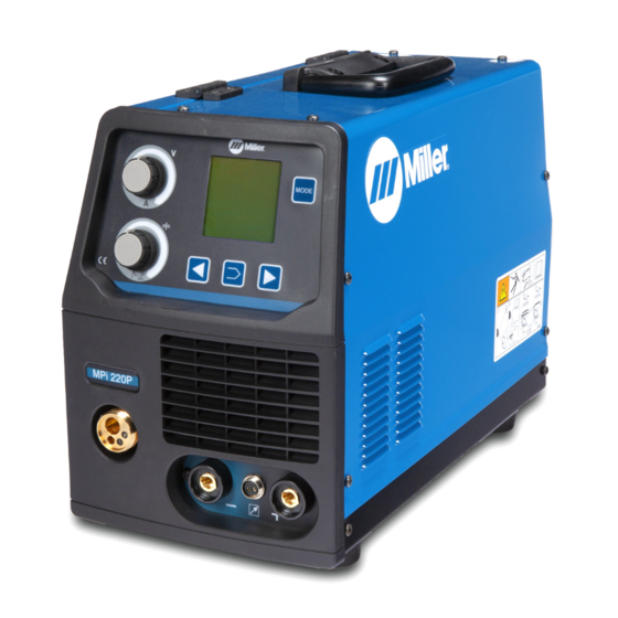
- Page 1 OM-253 918B 2012−02 Processes Multiprocess Welding Description MPi 220P File: Multiprocess Visit our website at www.MillerWelds.com...
- Page 2 Warranty and service information for your particular model are also provided. Miller Electric manufactures a full line of welders and welding related equipment. For information on other quality Miller products, contact your local Miller...
-
Page 3: Table Of Contents
TABLE OF CONTENTS SECTION 1 − SAFETY PRECAUTIONS - READ BEFORE USING ....... . . 1-1. - Page 4 TABLE OF CONTENTS SECTION 6 − MAINTENANCE & TROUBLESHOOTING ......... 6-1.
-
Page 5: Declaration Of Conformity
ITW Welding Products Italy S.r.l Via Privata Iseo 6/E, 20098 San Giuliano M.se, (MI) Italy declares that the product(s) identified in this declaration conform to the essential requirements and provisions of the stated Council Directive(s) and Standard(s). Product/Apparatus Identification: Product Stock Number MPi 220P 230VAC 059016014 Council Directives: 2006/95/EC Low Voltage 2004/108/EC Electromagnetic Compatibility Standards: IEC 609741 Arc Welding Equipment ... -
Page 7: Section 1 − Safety Precautions - Read Before Using
SECTION 1 − SAFETY PRECAUTIONS - READ BEFORE USING som 2011−10 Protect yourself and others from injury — read, follow, and save these important safety precautions and operating instructions. 1-1. Symbol Usage DANGER! − Indicates a hazardous situation which, if Indicates special instructions. - Page 8 D Remove stick electrode from holder or cut off welding wire at FUMES AND GASES can be hazardous. contact tip when not in use. D Wear oil-free protective garments such as leather gloves, heavy Welding produces fumes and gases. Breathing shirt, cuffless trousers, high shoes, and a cap.
-
Page 9: Additional Symbols For Installation, Operation, And Maintenance
1-3. Additional Symbols For Installation, Operation, And Maintenance FIRE OR EXPLOSION hazard. BATTERY EXPLOSION can injure. D Do not install or place unit on, over, or near D Do not use welder to charge batteries or jump combustible surfaces. start vehicles unless it has a battery charging feature designed for this purpose. -
Page 10: California Proposition 65 Warnings
1-4. California Proposition 65 Warnings Welding or cutting equipment produces fumes or gases This product contains chemicals, including lead, known to which contain chemicals known to the State of California to the state of California to cause cancer, birth defects, or other cause birth defects and, in some cases, cancer. -
Page 11: Section 2 − Definitions
SECTION 2 − DEFINITIONS Warning! Watch Out! There are possible 2.1 Keep your head out of the fumes. Arc rays can burn eyes and injure hazards as shown by the symbols. skin. 2.2 Use forced ventilation or local exhaust to remove the fumes. Electric shock can kill. - Page 12 Warning! Watch Out! There are possible hazards as shown by the symbols. Electric shock from wiring can kill. Disconnect input plug or power before working on machine. Read the Owner’s Manual before working on this machine. Consult rating label for input power requirements, and check power available at the job site −...
-
Page 13: Weee Label
Warning! Watch Out! There are possible hazards as shown by the symbols. Electric shock from wiring can kill. Read the Owner’s Manual before working on this machine. Wear approved safety glasses. Electrode Positive (Straight Polarity) Electrode Negative (Reverse Polarity) DCEP Electrode Positive DCEN Electrode Negative... -
Page 14: Symbols And Definitions
2-2. Symbols And Definitions Alternating Current Direct Current Amperes Volts (AC) (DC) Protective Earth Remote (Ground) Single Phase Static Frequency Gas Metal Arc Line Connection Converter- Single Phase Welding (GMAW) Transformer- Rectifier Rated Maximum Maximum Effective Conventional Load Primary Voltage 1max 1eff Supply Current... -
Page 15: Section 3 − Specifications
L = 548 230 Volts 100 A 130 A 180 A 5 - 200 A 65 V W = 237 MPi 220P IP22S 14.0 V 15.2 V 17.2 V 10.0 - 18.0 V H = 365 230 Volts 100 A... -
Page 16: Duty Cycle And Overheating
3-4. Duty Cycle And Overheating Duty Cycle is percentage of 10 minutes that unit can weld at rated load without overheating. If unit overheats, thermostat(s) opens, output stops, and cooling fan runs. Wait fifteen minutes for unit to cool. Reduce amperage or duty cycle before welding. -
Page 17: Volt-Ampere Curves
3-5. Volt-Ampere Curves The volt-ampere curves show the minimum and maximum voltage and amperage output capabilities of the welding power source. Curves of other settings fall between the curves shown. A. MIG 100 110 120 130 140 150 160 170 180 190 200 210 220 230 240 DC Amperes B. -
Page 18: Section 4 − Installation
SECTION 4 − INSTALLATION 4-1. Serial Number And Rating Label Location The serial number and rating information for this product is located on the bottom . Use rating label to determine input power requirements and/or rated output. For future reference, write serial number in space provided on back cover of this manual. Operating Temperature Range: 14... -
Page 19: Installing Gas Supply
4-3. Installing Gas Supply Obtain gas cylinder and chain to running gear, wall, or other stationary support so cylinder cannot fall and break off valve. Cylinder Valve Remove cap, stand to side of valve, and open valve slightly. Gas flow blows dust and dirt from valve. Close valve. -
Page 20: Weld Output Terminals And Selecting Cable Sizes
4-4. Weld Output Terminals And Selecting Cable Sizes* NOTICE − The Total Cable Length in Weld Circuit (see table below) is the combined length of both weld cables. For example, if the power source is 30 m (100 ft) from the workpiece, the total cable length in the weld circuit is 60 m (2 cables x 30 m). Use the 60 m (200 ft) column to determine cable size. -
Page 21: Changing Polarity
4-6. Changing Polarity Lead Connections For Direct Current Electrode Positive (DCEP) Lead Connections For Direct Current Electrode Negative (DCEN) Always read and follow wire manufacturer’s recommended polarity and see Section 4-5. 956142881_2-A OM-253 918 Page 15... -
Page 22: Installing Wire Spool And Adjusting Hub Tension
4-7. Installing Wire Spool And Adjusting Hub Tension Wire Spool 5 kg Handwheel Allows adjustment of hub tension. Turn handwheel clockwise to in- crease tension. Spool Holder Cap Tighten to secure wire spool. Tools Needed: 956142881_20-B OM-253 918 Page 16... -
Page 23: Changing Drive Rolls And Wire Inlet Guide
4-8. Changing Drive Rolls And Wire Inlet Guide Setscrew Inlet Wire Guide Loosen setscrew. Slide tip of guide as close to drive rolls as possible without touching. Tighten setscrew. Drive Roll The drive roll consists of two differ- ent sized grooves. The stamped markings on the end surface of the drive roll refers to the groove on the opposite side of the drive roll. -
Page 24: Aligning Drive Rolls And Wire Guide
4-9. Aligning Drive Rolls and Wire Guide Turn off and disconnect in- put power View is from top of drive rolls looking down with pressure assembly open. Correct Incorrect Drive Roll Securing Nut Drive Roll Wire Guide Welding Wire Drive Gear Insert screwdriver, and turn screw in or out until drive roll groove lines up with wire guide. -
Page 25: Electrical Service Guide
4-10. Electrical Service Guide Failure to follow these electrical service guide recommendations could create an electric shock or fire hazard. These recommendations are for a dedicated branch circuit sized for the rated output and duty cycle of the welding power source. 50/60 Hz Single Phase Input Voltage (V) -
Page 26: Connecting 230 Vac Single Phase Input Power
4-11. Connecting 230 VAC Single Phase Input Power Installation must meet all National and Local Codes − have only quali- fied persons make this installation. Disconnect and lockout/tagout in- put power before connecting input conductors from unit. Always connect green or green/ yellow conductor supply... -
Page 27: Threading Welding Wire And Adjusting Pressure Roll Tension
4-12. Threading Welding Wire And Adjusting Pressure Roll Tension Wire Spool Welding Wire Inlet Wire Guide Pressure Adjustment Knob Drive Roll Outlet Wire Guide Gun Conduit Cable Lay gun cable out straight. Tools Needed: Hold wire tightly to keep it from unraveling. -
Page 28: Section 5 − Operation
SECTION 5 − OPERATION 5-1. Controls Power Switch S1 Use switch to turn power on and off. Wire Speed/Set-Up Adjustment Control Use control to adjust wire speed and change values while in the set-up mode. Amperage/Workpiece Thickness Adjustment Control Use control to adjust welding am- perage while in TIG and STICK mode (see Section 5-2 or 5-3) or workpiece thickness while in MIG... -
Page 29: Preparing Unit For Stick Welding
5-2. Preparing Unit For Stick Welding Positive Weld Output Terminal Gun Trigger Receptacle Negative Weld Output Terminal Hot Start Adjustment Knob Amperage Adjustment Control Knob Digital Meter Display Process Selector P1 Push Button Welding Amperage Welding Voltage 10 Stick Welding Symbol 11 Set Amperage (Output On) 12 Hot Start Adjustment Switch 13 Sequencer Set-Up P2 Push... -
Page 30: Preparing Unit For Tig Welding
5-3. Preparing Unit For TIG Welding Positive Weld Output Terminal Gun Trigger Receptacle Negative Weld Output Terminal Hot Start Adjustment Knob Amperage Adjustment Control Knob Digital Meter Display Process Selector Switch Welding Amperage Welding Voltage 10 TIG Welding Symbol 11 Set Amperage 12 Hot Start Adjustment Switch Prepare unit for TIG welding as fol- lows:... - Page 31 5-4. 2T − 4T Trigger Mode Selection (TIG Process) Process Selection P1 Push Button Sequencer Set-Up P2 Push Button Sequencer Adjustment P3 Push Buttons Wire Feed Speed (WFS) Adjustment Knob While in TIG mode, select desired trigger mode as follows: Press and release P2 push button to enter in trigger mode set-up menu.
-
Page 32: Preparing Unit For Manual Mig (Gmaw And Fcaw) Welding Process
5-5. Preparing Unit For Manual MIG (GMAW And FCAW) Welding Process To select MIG welding proceed as follows: Prepare unit according to Section 4. Use a cable with correct adapter, connect gun to the MIG gun con- nector. For GMAW process: Connect wire drive lead to positive output terminal. -
Page 33: Manual Mig Welding Set-Up Menu
5-6. Manual MIG Welding Set-Up Menu To enter MIG welding set-up menu, proceed as follows: Sequencer Set-Up P2 Push Button Wire Feed Speed (WFS) Adjustment Knob While in the set-up menu, use knob to change sequencer parameters. Sequencer Adjustment/Operator Point Setting P3 Push Buttons (See Section 5-16) Process Selection P1 Push... - Page 34 5-6. Manual MIG Welding Set-Up Menu (Continued) In short circuit GMAW welding, an increase in inductance will decrease the number of short circuit transfers per second (provided no other changes are made) and increase the arc-on time. The increased arc-on time makes the welding puddle more fluid.
-
Page 35: Trigger Mode And Spot Time Selection (Mig Process)
5-7. Trigger Mode And Spot Time Selection (MIG Process) Always select a trigger mode. Digital Display Meter Sequencer Set-Up P3 Push Buttons Wire Feed Speed (WFS) Adjustment Knob Sequencer Adjustment/Operator Point Setting P2 Push Button To select trigger mode and spot weld timer, proceed as follows: Press and hold P2 push button to enter into the set-up menu. -
Page 36: Preparing Unit For Synergic Mig (Gmaw And Fcaw) Welding Process
5-8. Preparing Unit For Synergic MIG (GMAW And FCAW) Welding Process To select MIG welding process, proceed as follows: Prepare unit according to Section 4. Use a cable with correct adapter, connect gun to the MIG gun con- nector. For GMAW process: Connect wire drive lead to positive output terminal. -
Page 37: Synergic Mig Welding Set-Up Menu
5-9. Synergic MIG Welding Set-Up Menu To enter MIG welding set-up menu, proceed as follows: Sequencer Set-Up P2 Push Button Arc Length Control Knob While in the set-up menu, use knob to change sequencer parameters. Sequencer Adjustment/Operator Point Setting P3 Push Buttons (See Section 5-16) Process Selection P1 Push Button... - Page 38 5-9. Synergic MIG Welding Set-Up Menu (Continued) Percentage Of Weld Output Inductance Use Arc Length control knob to se- lect the percentage of welding in- ductance value. When selected, use the knob or sequencer P3 push buttons to change value. Default = 0% (min = −10%, max = +10%).
-
Page 39: Preparing Unit For Synergic Pulsed Mig (Gmaw And Fcaw) Welding Process
5-10. Preparing Unit For Synergic Pulsed MIG (GMAW And FCAW) Welding Process To select MIG welding process, proceed as follows: Prepare unit according to Section 4. Use a cable with correct adapter, connect gun to the MIG gun con- nector. For GMAW process: Connect wire drive lead to positive output terminal. - Page 40 5-10. Preparing Unit For Synergic Pulsed MIG (GMAW And FCAW) Welding Process (Continued) Set MIG welding process using pro- cess selection P1 push button. To enter synergic pulsed MIG mode, press and release sequencer set-up P2 push button. Use se- quencer adjustment P3 push but- tons until PULSED is displayed.
-
Page 41: Synergic Pulsed Mig Welding Set-Up Menu
5-11. Synergic Pulsed MIG Welding Set-Up Menu To enter MIG welding set-up menu, proceed as follows: Sequencer Set-Up P2 Push Button Arc Length Control Knob While in the set-up menu, use knob to change sequencer parameters. Sequencer Adjustment/Operator Point Setting P3 Push Buttons (See Section 5-16) Process Selection P1 Push Button... -
Page 42: Trigger Set-Up Menu (Synergic Pulsed Mig Welding Only)
5-12. 4T Trigger Set-Up Menu (Synergic Pulsed MIG Welding Only) To enter 4T trigger set-up menu: Follow instructions listed in Section 5-7. Postflow Time (See Section 5-11) Arc Power (Hot Start) Percentage Percent increase of welding current to make arc start easier. When this item is selected, use the Arc Length control knob or Sequencer adjust- ment P3 push buttons to change... -
Page 43: Welding Wire Loading Settings
5-13. Welding Wire Loading Settings Prepare unit for welding wire load- ing as follows: S Install wire spool and adjust hub tension (see Section 4-7). S Use proper drive rolls and wire guide (see Section 4-8). S Thread welding wire and adjust pressure roll tension (see Section 4-12). -
Page 44: Resetting Unit To Factory Default Settings
5-14. Resetting Unit To Factory Default Settings This procedure will delete all operator specified parameters and recall all factory paramet- ers. Power Switch Use power switch to turn unit on. When Miller appears on the display, press and release sequencer set-up P2 push button. -
Page 45: Operator Point Mig Parameters Loading
5-16. Operator Point MIG Parameters Loading This setting is only available in MIG mode. It allows the operat- or to load and save desired specified weld parameters and recall them when required. Store parameters: Press and release P3 push buttons simultaneously to enter the operat- or point set-up menu. -
Page 46: Rated Supply Current I1 = 16 Amps Setting
5-17. Rated Supply Current I = 16 Amps Setting This setting allows the operator to use the unit with a maximum of 16 amperes of rated supply current I Before setting the rated supply cur- rent I Follow the Electromagnetic Compatibility (EMC) inform- ation according to Section 3-2. -
Page 47: Basic Set-Up Menu Parameters Settings
5-18. Basic Set-Up Menu Parameters Settings Power Switch Use power switch to turn unit on. When Miller appears on the display, press and release sequencer set-up P2 push button. Basic set-up menu will be displayed. Initial Wire Feed Speed (WFS) Settings Press and release P2 push button to select desired parameter. -
Page 48: Section 6 − Maintenance & Troubleshooting
SECTION 6 − MAINTENANCE & TROUBLESHOOTING 6-1. Routine Maintenance Disconnect power Maintain more often before maintaining. during severe conditions. n = Check Z = Change ~ = Clean l = Replace Reference * To be done by Factory Authorized Service Agent Every Months l Unreadable Labels... -
Page 49: Troubleshooting
6-4. Troubleshooting A. MIG (GMAW) Welding Trouble Remedy Be sure line disconnect switch is On (see Section 4-11). No weld output; wire does not feed. Replace building line fuse or reset circuit breaker if open (see Section 4-11). Secure gun trigger connections (see welding gun Owner’s Manual). Check continuity of power switch S1 and replace if necessary. - Page 50 B. Stick (SMAW) Welding Trouble Remedy Hard starts, poor welding characterist- Use proper type and size of electrode. ics, unusual spattering. Check electrode polarity and reverse in necessary; check and correct poor connections Make sure a remote control is not connected. C.
- Page 51 Notes OM-2253 918 Page 45...
-
Page 52: Section 7 − Electrical Diagrams
SECTION 7 − ELECTRICAL DIAGRAMS Figure 7-1. Circuit Diagram For Welding Power Source OM-253 918 Page 46... - Page 53 956142882-B OM-2253 918 Page 47...
-
Page 54: Section 8 − Mig Welding (Gmaw) Guidelines
SECTION 8 − MIG WELDING (GMAW) GUIDELINES mig1 2009−12 8-1. Typical MIG Process Connections Weld current can damage electronic parts in vehicles. Disconnect both battery cables before welding on a vehicle. Place work clamp as close to the weld as possible. Regulator/ Flowmeter Wire Feeder/... -
Page 55: Typical Mig Process Control Settings
8-2. Typical MIG Process Control Settings These settings are guidelines only. Material and wire type, joint design, fitup, position, shielding gas, etc. affect settings. Test welds to be sure they comply to specifications. Material thickness determines weld parameters. 1/8 or 0.125 in. Convert Material Thickness to Amperage (A) -
Page 56: Holding And Positioning Welding Gun
8-3. Holding And Positioning Welding Gun Welding wire is energized when gun trigger is pressed. Before lowering helmet and pressing trigger, be sure wire is no more than 1/2 in. (13 mm) past end of nozzle, and tip of wire is positioned correctly on seam. Hold Gun and Control Gun Trigger Workpiece... -
Page 57: Conditions That Affect Weld Bead Shape
8-4. Conditions That Affect Weld Bead Shape Weld bead shape depends on gun angle, direction of travel, electrode extension (stickout), travel speed, thickness of base metal, wire feed speed (weld current), and voltage. Push Drag Perpendicular GUN ANGLES AND WELD BEAD PROFILES Short Normal Long... -
Page 58: Gun Movement During Welding
8-5. Gun Movement During Welding Normally, a single stringer bead is satisfactory for most narrow groove weld joints; however, for wide groove weld joints or bridging across gaps, a weave bead or multiple stringer beads works better. Stringer Bead − Steady Movement Along Seam Weave Bead −... -
Page 59: Troubleshooting − Excessive Spatter
8-8. Troubleshooting − Excessive Spatter Excessive Spatter − scattering of molten metal particles that cool to solid form near weld bead. S-0636 Possible Causes Corrective Actions Wire feed speed too high. Select lower wire feed speed. Voltage too high. Select lower voltage range. Electrode extension (stickout) too long. -
Page 60: Troubleshooting − Lack Of Penetration
8-11. Troubleshooting − Lack Of Penetration Lack Of Penetration − shallow fusion between weld metal and base metal. Lack of Penetration Good Penetration S-0638 Possible Causes Corrective Actions Improper joint preparation. Material too thick. Joint preparation and design must provide access to bottom of groove while maintaining proper welding wire extension and arc characteristics. -
Page 61: Troubleshooting − Waviness Of Bead
8-14. Troubleshooting − Waviness Of Bead Waviness Of Bead − weld metal that is not parallel and does not cover joint formed by base metal. S-0641 Possible Causes Corrective Actions Welding wire extends too far out of nozzle. Be sure welding wire extends not more than 1/2 in. (13 mm) beyond nozzle. Unsteady hand. -
Page 62: Common Mig Shielding Gases
8-16. Common MIG Shielding Gases This is a general chart for common gases and where they are used. Many different combinations (mixtures) of shielding gases have been developed over the years. The most commonly used shielding gases are listed in the following table. - Page 63 Problem Probable Cause Remedy Wire slipping in drive rolls. Adjust pressure setting on wire feed rolls. Replace worn Welding arc not stable. drive rolls if necessary. Wrong size gun liner or contact tip. Match liner and contact tip to wire size and type. Incorrect voltage setting for selected wire feed speed on Readjust welding parameters.
-
Page 64: Section 9 − Stick Welding (Smaw) Guidelines
SECTION 9 − STICK WELDING (SMAW) GUIDELINES 9-1. Stick Welding Procedure Weld current starts when electrode touches work- piece. Equipment Needed: Tools Needed: Weld current can damage electronic parts in vehicles. Disconnect both battery cables before welding on a vehicle. Place work clamp as close to the weld as possible. -
Page 65: Electrode And Amperage Selection Chart
9-2. Electrode and Amperage Selection Chart 6010 DEEP 3/32 MIN. PREP, ROUGH HIGH SPATTER 6011 DEEP 6010 5/32 & 6013 EP,EN GENERAL 3/16 6011 7/32 SMOOTH, EASY, 7014 EP,EN FAST 1/16 LOW HYDROGEN, 7018 5/64 STRONG 3/32 FLAT SMOOTH, EASY, 7024 EP,EN HORIZ... - Page 66 9-4. Positioning Electrode Holder End View Of Work Angle Side View Of Electrode Angle Groove Welds Fillet Welds S-0060 9-5. Poor Weld Bead Characteristics Large Spatter Deposits Rough, Uneven Bead Slight Crater During Welding Bad Overlap Poor Penetration S-0053-A...
-
Page 67: Electrode Movement During Welding
9-7. Conditions That Affect Weld Bead Shape Weld bead shape is affected electrode angle, length, travel speed, and thick- ness of base metal. Correct Angle Angle Too Large - Angle Too Small Electrode Angle Drag Spatter Arc Length Normal Too Long Too Short... -
Page 68: Lap Joint
9-9. Groove (Butt) Joints Tack Welds Prevent edges of joint from draw- ing together ahead of electrode by tack welding the materials in posi- tion before final weld. Square Groove Weld Good for materials up to 3/16 in. (5 mm) thick. Single V-Groove Weld Good for materials 3/16 −... -
Page 69: Weld Test
9-12. Weld Test Vise Weld Joint Hammer Strike weld joint in direction shown. A good weld bends over but does not break. 2 To 3 in. (51-76 mm) 2 To 3 in. (51-76 mm) 1/4 in. (6.4 mm) S-0057-B 9-13. Troubleshooting Porosity −... - Page 70 Lack Of Penetration − shallow fusion between weld metal and base metal. Lack of Penetration Good Penetration Possible Causes Corrective Actions Improper joint preparation. Material too thick. Joint preparation and design must provide access to bottom of groove. Improper weld technique. Keep arc on leading edge of weld puddle.
-
Page 71: Section 10 − Selecting And Preparing Atungsten For Dc Or Ac Welding With Inverter Machines
SECTION 10 − SELECTING AND PREPARING A TUNGSTEN FOR DC OR AC WELDING WITH INVERTER MACHINES gtaw_Inverter_2011-06 Whenever possible and practical, use DC weld output instead of AC weld output. 10-1. Selecting Tungsten Electrode ( Wear Clean Gloves To Prevent Contamination Of Tungsten Not all tungsten electrode manufacturers use the same colors to identify tungsten type. -
Page 72: Section 11 − Guidelines For Tig Welding (Gtaw)
SECTION 11 − GUIDELINES FOR TIG WELDING (GTAW) 11-1. Positioning The Torch Grinding the tungsten electrode produces dust and flying sparks which can cause injury and start fires. Use local exhaust (forced ventilation) at the grinder or wear an approved respirator. Read MSDS for safety information. -
Page 73: Torch Movement During Welding
11-2. Torch Movement During Welding Tungsten Without Filler Rod Welding direction Form pool Tilt torch Move torch to front of pool. Repeat process. Tungsten With Filler Rod Welding direction Form pool Tilt torch Add filler metal Remove rod Move torch to front of pool. -
Page 74: Section 12 − Parts List
SECTION 12 − PARTS LIST Hardware is common and not available unless listed. 956142881_17-B Figure 12-1. Main Assembly OM-253 918 Page 68... - Page 75 956142878 Rating Plate, Mpi 220P ..........
- Page 76 See Drive Roll And Wire Guide Kits Hardware is common and not available unless listed. 956142881_18-A Figure 12-2. Wire Drive Assembly OM-253 918 Page 70...
- Page 77 Item Dia. Part Mkgs. Description Quantity Figure 12-2. Wire Drive Assembly ..056126081 Motor, Gear ............
- Page 78 Table 12-1. Drive Roll And Wire Guide Kits Base selection of drive rolls upon the following recommended usages: 1. V-Grooved rolls for hard wire. 2. U-Grooved rolls for soft and soft shelled cored wires. 3. V-Knurled rolls for hard shelled cored wires. 4.
- Page 79 Effective January 1, 2012 (Equipment with a serial number preface of MC or newer) This limited warranty supersedes all previous Miller warranties and is exclusive with no other guarantees or warranties expressed or implied. LIMITED WARRANTY − Subject to the terms and conditions 90 Days —...
- Page 80 File a claim for loss or damage during Phone: 39 (0) 2982901 Fax: 39 (0) 298290-203 shipment. email: miller@itw−welding.it For assistance in filing or settling claims, contact your distributor and/or equipment manufacturer’s Transportation Department. ORIGINAL INSTRUCTIONS − PRINTED IN USA 2012 Miller Electric Mfg. Co. 2012−01...
Need help?
Do you have a question about the MPi 220P and is the answer not in the manual?
Questions and answers