Table of Contents
Advertisement
Advertisement
Table of Contents

Related Manuals for SOYO SY-5SSM


Summary of Contents for SOYO SY-5SSM
-
Page 1: Technical Reference
SY-5SSM V1.1 SY-5SSM/5 V1.1 Super 7 Motherboard ************************************************ ® Pentium Class CPU supported SiS530 PCI/AGP Motherboard Micro-ATX Form Factor 3D AGP & Audio On-board ************************************************ User's Guide & Technical Reference... -
Page 2: Declaration Of Conformity
The following designated product EQUIPMENT: Main Board MODEL NO.: SY-5SSM which is the Class B digital device complies with 47 CFR Parts 2 and 15 of the FCC rules. Operation is subject to the following two conditions : (1) this device may not cause harmful interference, and (2) this device must accept any interference received, including interference that may cause undesired operation. -
Page 3: About This Guide
Our customers should ensure that their use of our products does not infringe upon any patents. It is the policy of Soyo Computer Inc. to respect the valid patent rights of third parties and not to infringe upon or assist others to infringe upon such rights. -
Page 4: Table Of Contents
Table of Contents SY-5SSM & SY-5SSM/5 V1.1 Table of Contents SY-5SSM & SY-5SSM/5 V1.1 MOTHERBOARD LAYOUT ....1 CHAPTER 1 INTRODUCTION............1 KEY FEATURES ............2 HANDLING THE MOTHERBOARD ....... 5 ELECTROSTATIC DISCHARGE PRECAUTIONS..5 CHAPTER 2 HARDWARE SETUP ............ 6 PREPARATIONS ............6... -
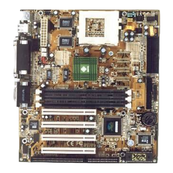
Page 5: Sy-5Ssm & Sy-5Ssm/5 V1.1 Motherboard Layout
SY-5SSM & SY-5SSM/5 V1.1 Motherboard Layout SY-5SSM & SY-5SSM/5 V1.1 Motherboard Layout for model 5SSM only (1 MB Cache) featuring two P.B. SRAM. PS/2 KB PS/2 Mouse Connector Connector JP30 P.B. SRAM USB 1 USB 2 64K X 64 Power... -
Page 6: Chapter 1 Introduction
Introduction SY-5SSM & SY-5SSM/5 V1.1 Chapter 1 INTRODUCTION The SY-5SSM & SY-5SSM/5 V1.1 AGP/PCI Motherboard is a high- performance MICRO-ATX form-factor system board. SY-5SSM & SY-5SSM/5 V1.1 use the SiS530 PCI Chipset technology and ® support Pentium class processors. This Motherboard is fully compatible with industry standards and adds many technical enhancements. - Page 7 Introduction SY-5SSM & SY-5SSM/5 V1.1 SY-5SSM & SY-5SSM/5 V1.1 PLATFORM FEATURES Board Size 4-layer PCB, 22x24.4cm(8.7”x9.6”), MICRO-ATX Form Factor ® Socket 7 Socket for Pentium class CPUs with host bus frequency of 66/100MH; Supports: Ø Intel Pentium ® Processors P54C/P55C (100- 233MHz) Ø...
- Page 8 Introduction SY-5SSM & SY-5SSM/5 V1.1 1 Floppy Disk Drive (FDD) Port (Supports 1.2MB/1.44MB/2.88MB and LS120/3- mode FDD) COM2 1 x 9-pin RS-232 Serial Connector 5-pin Serial Infrared Device Connector Keylock 5-pin KeyLock Connector Reset 2-pin Reset Switch Connector Speaker 4-pin PC Speaker Connector...
-
Page 9: Handling The Motherboard
Introduction SY-5SSM & SY-5SSM/5 V1.1 1-2 HANDLING THE MOTHERBOARD To avoid damage to your Motherboard, follow these simple rules while unpacking: Ø Before handling the Motherboard, ground yourself by Touching an unpainted portion of the system's metal chassis. Ø Remove the Motherboard from its anti-static packaging. Hold the Motherboard by the edges and avoid touching its components. -
Page 10: Chapter 2 Hardware Setup
Do I need to install a VGA card? Do I also need to install a sound card? The answer is NO to both questions above, since, the SY-5SSM V1.1 or SY-5SSM/5 V1.1 Motherboard already features one built-in VGA port and three built-in audio-stereo ports (Line-out, Line-in, Microphone). -
Page 11: Unpacking The Motherboard
Hardware Setup SY-5SSM & SY-5SSM/5 V1.1 2-2 Unpacking the Motherboard When unpacking the Motherboard, check for the following items: Ø The SY-5SSM V1.1 or SY-5SSM/5 V1.1 SiS530 PCI/AGP Motherboard Ø This Quick Start Guide * Ø The Installation CD-ROM * Ø... -
Page 12: Installation Guide
Hardware Setup SY-5SSM & SY-5SSM/5 V1.1 2-3 Installation Guide We will now begin the installation of the Motherboard. Please follow the step-by-step procedure designed to lead you to a complete and correct installation. Step 1. CPU Installation ® Follow these instructions to install your Pentium class processor correctly. - Page 13 Hardware Setup SY-5SSM & SY-5SSM/5 V1.1 Follow these steps to install the CPU in the Socket 7: Lift the socket handle up to a vertical position. Align the blunt edge of the CPU with the matching pinhole edge on the socket.
- Page 14 Hardware Setup SY-5SSM & SY-5SSM/5 V1.1 Step 3. CPU Voltage Setting (JP30) 1 3 5 7 CPU Voltage ® Please verify the correct voltage with your dealer before installation. Use the following tables to set JP30 to the proper "Voltage Value", according to the specifications marked on your CPU: This Motherboard comes with pre-configured setting of CPU voltage.
- Page 15 Hardware Setup SY-5SSM & SY-5SSM/5 V1.1 Those processors may come in various voltages on different markets. Therefore, always make sure you know the type of the CPU you are installing and adjust the settings on JP30 accordingly. This Motherboard supports CPU voltages from 2.0 to 3.52V in 0.1V increments.
- Page 16 Hardware Setup SY-5SSM & SY-5SSM/5 V1.1 Voltage Settings for Various Processors Processor Voltage Value: JP30 Voltage Setting 2 4 6 8 10 Intel P54C - 100 Vcore:3.3V Intel P54C - 133 VI/O:3.3V 1 3 5 7 9 2 4 6 8 10 Intel P54C - 166 Vcore:3.52V...
- Page 17 Hardware Setup SY-5SSM & SY-5SSM/5 V1.1 Voltage Settings for Various Processors (continued) Processor Voltage Value: JP30 Voltage Setting AMD K6-2 450 2 4 6 8 10 AMD K6-2 475 Vcore:2.2V AMD K6-2 500 VI/O:3.3V 1 3 5 7 9 AMD K6-III 400...
- Page 18 2 4 6 1 3 5 JP32 Host Bus Frequency ® The SY-5SSM V1.1 or SY-5SSM/5 V1.1 Motherboard is designed to ® support most Pentium class processors currently on the market. Jumpers SW1 and JP32 are used to configure the Motherboard...
- Page 19 Hardware Setup SY-5SSM & SY-5SSM/5 V1.1 CPU FREQUENCY & SDRAM frequency SETTING (SW1,JP32) Configure the SW1 jumpers to the settings that match your CPU speed. Refer to the following tables to set the Frequency Multiplier and Host Bus Frequency of your CPU:...
- Page 20 Hardware Setup SY-5SSM & SY-5SSM/5 V1.1 Please refer to the following table that gives you the correct frequency settings for the specific brand and model of CPU you are installing on this Motherboard. ® Frequency Settings for Intel Processors CPU Host...
- Page 21 Hardware Setup SY-5SSM & SY-5SSM/5 V1.1 Frequency Settings for AMD ™ Processors Frequency Processor CPU Host Bus Frequency Setting Ratio Multiplier: Setting: JP32 Clock Clock 2 4 6 AMD K5 - PR100 1.5 x 66MHz 33MHz 1 3 5 2 4 6 AMD K5 - PR133 2.0 x 66MHz...
- Page 22 Hardware Setup SY-5SSM & SY-5SSM/5 V1.1 Frequency Settings for AMD ™ Processors (Continued) Frequency Processor CPU Host Bus Frequency Setting Ratio Multiplier: Setting: JP32 Clock Clock 2 4 6 AMD K6-2 333 3.5 x 95MHz 31.7MHz 1 3 5 2 4 6 AMD K6-2 350 3.5 x 100MHz...
- Page 23 Hardware Setup SY-5SSM & SY-5SSM/5 V1.1 Frequency Settings for Cyrix ™ Processors CPU Host Frequency Processor Frequency Setting Ratio Bus Setting: Multiplier: Clock Clock JP32 2 4 6 Cyrix 6x86 - PR166+ 2.0 x 66MHz 33MHz 1 3 5 2 4 6 Cyrix 6x86 - PR200+ 2.0 x...
- Page 24 Hardware Setup SY-5SSM & SY-5SSM/5 V1.1 Frequency Settings for Cyrix ™ Processors (Continued) CPU Host Bus Frequency Processor Frequency Setting Ratio Setting: JP32 Multiplier: Clock Clock 2 4 6 Cyrix M II - 350** 3.0 x 90MHz 30MHz 1 3 5...
- Page 25 Hardware Setup SY-5SSM & SY-5SSM/5 V1.1 Frequency Settings for IDT ™ Processors Frequency Processor CPU Host Bus Frequency Setting Ratio Multiplier: Setting: JP32 Clock Clock 2 4 6 IDT X86 CPU 2-300 2.5 x 100MHz 33MHz 1 3 5 ** Set the proper CPU frequency according to the marking on the CPU.
- Page 26 Hardware Setup SY-5SSM & SY-5SSM/5 V1.1 Step 5. DRAM Module Installation This Motherboard supports three DIMM banks from 8 to 256 MB with no other restrictions on memory configurations. You can install the memory in any combination without having to rely on a memory configuration table.
-
Page 27: Memory Configuration Table
Hardware Setup SY-5SSM & SY-5SSM/5 V1.1 MEMORY CONFIGURATION This Motherboard features 3 x DIMM Banks for 168-pin 3.3V unbuffered DIMM modules Your board comes with three DIMM sockets, providing support for up to 768MB of main memory using DIMM modules from 8MB to 256MB. - Page 28 Hardware Setup SY-5SSM & SY-5SSM/5 V1.1 Connect one side of the 34-pin flat cable to the floppy drive and plug the other end to the floppy drive connector on the Motherboard. This Motherboard can support up to 2 floppy drives.
- Page 29 Hardware Setup SY-5SSM & SY-5SSM/5 V1.1 cause the system to restart the boot-up sequence. 3. Speaker Attach the 4-pin PC speaker cable from the case to the Speaker connector on the Motherboard. 4. ACPI/APM LED Connecting the 2-pin ACPI LED cable to the corresponding ACPI/APM connector on the motherboard.
- Page 30 Hardware Setup SY-5SSM & SY-5SSM/5 V1.1 Step 9. Back Panel Connections All external devices such as the keyboard, printer, PS/2 mouse, modem, USB, monitor, joystick and audio devices (speakers/ headphones, microphone and CD/cassette player) can be plugged directly onto the Motherboard back panel.
- Page 31 Hardware Setup SY-5SSM & SY-5SSM/5 V1.1 and modem. Plug the serial device cables directly into the COM1 9-pin male connector located at the rear panel of the Motherboard. 2. Parallel Port PRT This parallel port is used to connect the printer or other parallel devices.
- Page 32 Hardware Setup SY-5SSM & SY-5SSM/5 V1.1 Step 10. Other Connections 1. Serial Port COM 2 In addition to the onboard serial connector COM1 located at the rear panel, your Motherboard comes with a second serial port COM2 equipped with a flat cable and external connector.
- Page 33 Hardware Setup SY-5SSM & SY-5SSM/5 V1.1 2. Wake-On-LAN (WOL) Attach the 3-pin connector from the LAN card which supports the Wake-On-LAN (WOL) function to the JP44 connector on the Motherboard. This WOL function lets users wake up the connected computer through the LAN card.
- Page 34 Hardware Setup SY-5SSM & SY-5SSM/5 V1.1 4. CD Line-in (CDIN1,CDIN2) This Motherboard provides two CD-Line in connectors. Please connect the 4-pin audio cable from your CD-ROM drive to either CDIN1 or CDIN2. (It fits in only one, depending on the cable that...
- Page 35 Hardware Setup SY-5SSM & SY-5SSM/5 V1.1 Step 11. CPU Cooling Fan Installation After you have seated the CPU cooling fan properly on the processor, attach the 3-pin fan cable to the CPUFAN connector on the Motherboard. To avoid damage to the system, install according to the following pin...
-
Page 36: Atx Power
Hardware Setup SY-5SSM & SY-5SSM/5 V1.1 Step 13. ATX Power Supply Plug the connector from the power directly into the 20-pin male ATX PW connector on the Motherboard, as shown in the following figure. ATX Power ® Warning: Follow these precautions to preserve your... - Page 37 Hardware Setup SY-5SSM & SY-5SSM/5 V1.1 Please install the ATX power according to the following pin assignment: ATX Power 3.3V 3.3V -12V 3.3V PS-ON Ø Pay special care to the directionality. PW-OK 5VSB Step 14. Select the CPU Burst Mode (J1)
- Page 38 Hardware Setup SY-5SSM & SY-5SSM/5 V1.1 Step 15. CMOS Clearing (JP5) After you have turned off your computer, clear the CMOS memory by momentarily shorting pins 2-3 on jumper JP5, for a few seconds. Then restore JP5 to the initial 1-2 jumper setting in order to recover and retain the default settings.
- Page 39 Hardware Setup SY-5SSM & SY-5SSM/5 V1.1 Step 18. CACHE CONFIGURATION This Motherboard has a built-in 512KB/1MB Level 2 Pipelined Burst cache onboard to improve the system performance. The cache size and RAM locations are specified as follows: Cacheable Cache Size...
-
Page 40: Hardware Setup
Hardware Setup SY-5SSM & SY-5SSM/5 V1.1 Repeat this operation until you get the following screen. 3. The BIOS Setup screen appears: ROM PCI/ISA BIOS CMOS SETUP UTILITY AWARD SOFTWARE, INC. STANDARD CMOS SETUP INTEGRATED PERIPHERALS BIOS FEATURES SETUP SUPERVISOR PASSWORD... -
Page 41: Chapter 3 Bios Setup Utility
BIOS Setup Utility SY-5SSM & SY-5SSM/5 V1.1 Chapter 3 BIOS SETUP UTILITY This Motherboard's BIOS setup program uses the ROM PCI/ISA BIOS program from Award Software Inc. To enter the Award BIOS program's Main Menu: 1. Turn on or reboot the system. -
Page 42: Main Menu
BIOS Setup Utility SY-5SSM & SY-5SSM/5 V1.1 Hot Keys: Function keys give you access to a group of commands throughout the BIOS utility. Function Command Description Help Gives the list of options available for each item. Color Change the color of the display window. -
Page 43: Standard Cmos Setup
BIOS Setup Utility SY-5SSM & SY-5SSM/5 V1.1 3-1 STANDARD CMOS SETUP Select the [STANDARD CMOS SETUP] option from the Main Menu and press [Enter] key. ROM PCI/ISA BIOS STANDARD CMOS SETUP AWARD SOFTWARE, INC. Date (mm:dd:yy) : Fri, May 29 1998... - Page 44 BIOS Setup Utility SY-5SSM & SY-5SSM/5 V1.1 3-1.2 Hard Disks Type & Mode Choose the type and mode for the hard disks that you have already installed. Primary Setting Description Note (Secondary) Master & Slave Type Auto BIOS detects hard disk type Default automatically.
- Page 45 BIOS Setup Utility SY-5SSM & SY-5SSM/5 V1.1 3-1.4 Video Select the video mode: EGA/VGA (Default), CGA 40, CGA 80, Mono (Monochrome). 3-1.5 Halt On When the BIOS detects system errors, this function will stop the system. Select which type of error will cause the system halt: All Errors (Default), No Errors, All But Diskette, All But Keyboard, All But Disk/Key.
-
Page 46: Bios Features Setup
BIOS Setup Utility SY-5SSM & SY-5SSM/5 V1.1 3-2 BIOS FEATURES SETUP Select the [BIOS FEATURES SETUP] option from the Main Menu and press [Enter] key. ROM PCI/ISA BIOS BIOS FEATURES SETUP AWARD SOFTWARE, INC. Virus Warning : Disabled Video BIOS Shadow... - Page 47 BIOS Setup Utility SY-5SSM & SY-5SSM/5 V1.1 3-2.1 Virus Warning Setting Description Note Virus Warning Disabled Default Enabled Enable this option to protect the boot sectors and partition tables of your hard disk. Any attempt to write to them will the system to halt and display a warning message.
- Page 48 BIOS Setup Utility SY-5SSM & SY-5SSM/5 V1.1 3-2.3 System Boot Control Settings System Boot Setting Description Note Control Settings Quick Power On Disabled Self Test Enabled Provides a fast POTS at Defaul boot-up. Boot Sequence A, C, SCSI Choose the boot...
-
Page 49: Bios Setup Utility
BIOS Setup Utility SY-5SSM & SY-5SSM/5 V1.1 3-2.4 Typematic Settings Typematic Settings Setting Description Note Typematic Disabled Default Rate Setting Enabled Enables to adjust the keystroke repeat rate. The following [Typematic Rate] and [Typematic Delay] fields are active only if... - Page 50 BIOS Setup Utility SY-5SSM & SY-5SSM/5 V1.1 3-2.5 Other Control Options Other Control Setting Description Note Options Security Setup Use this feature to prevent Default Option Unauthorized system boot-up or use of BIOS Setup. “Setup”, If a password is set,...
- Page 51 BIOS Setup Utility SY-5SSM & SY-5SSM/5 V1.1 Other Control Options (Continued) Other Control Setting Description Note Options Video or Disabled Adapter BIOS Enabled Default Shadow The BIOS is shadowed in a 16K segment if it is enabled and if it has BIOS present.
-
Page 52: Chipset Features Setup
BIOS Setup Utility SY-5SSM & SY-5SSM/5 V1.1 3-3 CHIPSET FEATURES SETUP Caution: Change these settings only if you are already familiar with the Chipset. The [CHIPSET FEATURES SETUP] option changes the values of the chipset registers. These registers control the system options in the computer. - Page 53 BIOS Setup Utility SY-5SSM & SY-5SSM/5 V1.1 CHIPSET FEATURES SETUP CHIPSET Setting Description Note FEATURES Ref/Act Set the DRAM clock of the Default Command Delay 5T,7T, 8T refresh command to refresh/active command delay. Refresh Queue Set the depth of refresh...
- Page 54 BIOS Setup Utility SY-5SSM & SY-5SSM/5 V1.1 CHIPSET FEATURES SETUP (Continued) CHIPSET Setting Description Note FEATURES Linear Mode Disabled Select Enabled if your Default SRAM Support system contains a CPU that Enabled requires linear mode (e.g., Cyrix M1/M2 CPU). DRAM 1 Cycle...
- Page 55 BIOS Setup Utility SY-5SSM & SY-5SSM/5 V1.1 CHIPSET FEATURES SETUP (Continued) CHIPSET Setting Description Note FEATURES Memory Hole Disabled Default At 15M-16M Enabled Some interface cards will map their ROM address to this area. If this occurs, select [Enabled] in this field.
-
Page 56: Power Management Setup
BIOS Setup Utility SY-5SSM & SY-5SSM/5 V1.1 3-4 POWER MANAGEMENT SETUP The [POWER MANAGEMENT SETUP] sets the system's power saving functions. ROM PCI/ISA BIOS POWER MANAGEMENT SETUP AWARD SOFTWARE, INC. ACPI function : Enabled VGA Activity : Enabled Power Management... - Page 57 BIOS Setup Utility SY-5SSM & SY-5SSM/5 V1.1 3-4.1 Power Management Controls Power Setting Description Note Management Controls ACPI Disabled Default function Enabled Enabled if you use Windows 98 and want to use ACPI Power User Define Lets you define the HDD and Management system power down times.
- Page 58 BIOS Setup Utility SY-5SSM & SY-5SSM/5 V1.1 Power Management Controls (Continued) Power Setting Description Note Management Controls Stdby Speed Select a divisor to reduce Default (div by) the CPU speed during Standby mode to a fraction of the full CPU speed. The...
- Page 59 BIOS Setup Utility SY-5SSM & SY-5SSM/5 V1.1 3-4.2 PM Timers PM Timers Setting Description Note The following [HDD Power Down] field may be configured only if [Power Management] is set to [User Define] HDD Off Disabled By default, this item is...
- Page 60 BIOS Setup Utility SY-5SSM & SY-5SSM/5 V1.1 3-4.3 PM Events PM Events Setting Description Note HDD Ports Disabled Activity Enabled When set to Enabled (default), any Default event occurring at a HDD (serial) port will awaken a system which has been powered down.
- Page 61 BIOS Setup Utility SY-5SSM & SY-5SSM/5 V1.1 PM Events (Continued) PM Events Setting Description Note IRQ 8 Break Disabled Default Suspend Enabled You can Enable or Disable monitoring of IRQ8 (the Real Time Clock) so it does not awaken the system from Suspend mode.
-
Page 62: Pnp/Pci Configuration Setup
BIOS Setup Utility SY-5SSM & SY-5SSM/5 V1.1 3-5 PNP/PCI CONFIGURATION SETUP This option sets the Motherboard's PCI Slots. ROM PCI/ISA BIOS PNP/PCI CONFIGURATION SETUP AWARD SOFTWARE, INC. Resources Controlled By : Manual PCI IRQ Actived By : Level Reset Configuration Data... - Page 63 BIOS Setup Utility SY-5SSM & SY-5SSM/5 V1.1 3-5.1 PNP/PCI Configuration Controls PNP/PCI Setting Description Note Controls Resources Manual BIOS does not manage PCI/ISA Controlled By PnP card IRQ assignment. Requires to assign IRQ-# and DMA-# to PCI or ISA PnP manually.
- Page 64 BIOS Setup Utility SY-5SSM & SY-5SSM/5 V1.1 3-5.3 PNP/PCI Configuration Setup PNP/PCI Setup Setting Description Note Under this item the user can assign an IRQ to a PCI slot. However, there under some conditions the IRQ will not be assigned as selected under this item: 1.
-
Page 65: Load Setup Defaults
BIOS Setup Utility SY-5SSM & SY-5SSM/5 V1.1 3-6 LOAD SETUP DEFAULTS Select the [LOAD SETUP DEFAULTS] option from the Main Menu to load the system values you have previously saved. This option is recommended if you need to reset the system setup and to retrieve the old values. -
Page 66: Integrated Peripherals
BIOS Setup Utility SY-5SSM & SY-5SSM/5 V1.1 3-8 INTEGRATED PERIPHERALS Caution: Change these settings only if you are already familiar with the Chipset. The [INTEGRATED PERIPHERALS] option changes the values of the chipset registers. These registers control the system options in the computer. - Page 67 BIOS Setup Utility SY-5SSM & SY-5SSM/5 V1.1 3-8.1 IDE Device Controls IDE Controls Setting Description Note Internal PCI/IDE Both Selects which PCI IDE Default controller to use. Disabled Primary Secondary The following fields may be configured only if [Internal PCI/IDE] is set to [Both], [Primary], or [Secondary].
- Page 68 BIOS Setup Utility SY-5SSM & SY-5SSM/5 V1.1 3-8.2 FDC Controls FDC Controls Setting Description Note Onboard FDC Disabled Turn off the on-board controller floppy controller Enabled Use the on-board Default floppy controller 3-8.3 Onboard Serial Ports Onboard Serial Setting Description...
- Page 69 BIOS Setup Utility SY-5SSM & SY-5SSM/5 V1.1 3-8.6 Parallel Ports Parallel Ports Setting Description Note Parallel Port Mode ECP + EPP The mode depends on your external device Normal Default that connects to this port. 3-8.7 PS/2 mouse Controls PS/2 mouse Controls...
- Page 70 BIOS Setup Utility SY-5SSM & SY-5SSM/5 V1.1 3-8.10 VGA Shared Control Setting VGA Shared Setting Description Note Control Setting VGA Shared 2 MB VGA memory size shared Default Memory Size 4-8 MB with system memory. None 3-8.11 CPU Device Monitoring...
-
Page 71: Supervisor Password
BIOS Setup Utility SY-5SSM & SY-5SSM/5 V1.1 3-9 SUPERVISOR PASSWORD Based on the setting you have made in the [Security Option] of the [BIOS FEATURES SETUP] section, the password prevents access to the system or the setup program by unauthorized users. Follow... -
Page 72: User Password
BIOS Setup Utility SY-5SSM & SY-5SSM/5 V1.1 Enter your new password and press [Enter]. The following message appears, prompting to confirm the new password: Confirm Password: Re-enter your password and then press [Enter] to exit to the Main Menu. This diagram outlines the password selection procedure: Type the Password Press <Enter>... -
Page 73: Ide Hdd Auto Detection
BIOS Setup Utility SY-5SSM & SY-5SSM/5 V1.1 3-11 IDE HDD AUTO DETECTION This Main Menu function automatically detects the hard disk type and configures the STANDARD CMOS SETUP accordingly. ROM PCI/ISA BIOS CMOS SETUP UTILITY AWARD SOFTWARE, INC. HARD DISKS... -
Page 74: Chapter 4 Drivers Installation
Insert the SOYO CD into the CD-ROM drive Step 1. The SOYO CD will auto-run, and the SOYO CD Start Up Menu will display as shown below. If you use Windows NT, the SOYO-CD will not detect your motherboard type. In that case the following dialog will pop up, please choose your motherboard and press OK. -
Page 75: Install Drivers And Utilities
Drivers Installation SY-5SSM & SY-5SSM/5 V1.1 The user's manual files included on the SOYO CD are in PDF (Postscript Document) format. In order to read a PDF file, the appropriate Acrobat Reader software must be installed in your system. Install Drivers and Utilities Step 2. - Page 76 Drivers Installation SY-5SSM & SY-5SSM/5 V1.1 driver revision: SIS 530 VGA drivers SIS 530 busmaster drivers SIS system hardware monitor 4.05.00.1087 ESS Windows 9x drivers (for PCI) 4.05.13 ESS Windows NT drivers (for PCI) V2.20 ESS Soundtrack Program (for PCI) (Driver Installation Menu) We recommend that you only install those drivers.
- Page 77 Check the Latest Releases Step 3. Click the 'Check the latest Releases' button to go the SOYO Website to automatically find the latest BIOS, manual and driver releases for your motherboard. This button will only work if your computer is connected to the internet through a network or modem connection.
-
Page 78: Onboard Vga
Onboard VGA and Audio SY-5SSM & SY-5SSM/5 V1.1 Chapter 5 Onboard VGA and Audio 5-1 Onboard VGA This Motherboard offers an onboard Video Graphics Accelerator (VGA), provided by the SiS530 chipset and related application programs. Note: Please refer to Chapter 6- SiS VGA Driver Installation for a detailed procedure on how to install the video driver depending on the particular environment ( Win NT 4.0, Win 95/98) installed on your system. - Page 79 Onboard VGA and Audio SY-5SSM & SY-5SSM/5 V1.1 Video Functions Support single frame buffer architecture to save the DRAM cost Support graphics/video overlay function by color-key and/or chroma-key operations Support multi-format Video For windows such as YUV420, YUV422, RGB565, and RGB555...
-
Page 80: Onboard Joystick Port
This Motherboard features three built-in audio-stereo ports (labeled line-in, line-out, and mic jack) convenient to directly plug-in all your external audio devices. Your SY-5SSM V1.1 or SY-5SSM/5 V1.1 Motherboard is making use of the ES1938 sound chipset technology and applications programs. - Page 81 Onboard VGA and Audio SY-5SSM & SY-5SSM/5 V1.1 Software Support Windows 3.1 Windows 95/98 Windows NT 4.0 Windows Sound System All DOS-based Games Compatibility Sound Blaster ™ Sound Blaster Pro ™ Sound Blaster 16 ™ Emulation Windows Sound System ™...
- Page 82 Onboard VGA and Audio SY-5SSM & SY-5SSM/5 V1.1 Connecting Speakers You can connect external speakers to the "Line-out" port on your SY-5SSM V1.1 or SY-5SSM/5 V1.1 Motherboard. LINE-OUT LINE-IN MIC JACK (Amplified Speakers) Note: This Motherboard requires a speaker with built-in amplifier (Amplified Speaker) to generate proper output sound volume.
-
Page 83: Chapter 5 Onboard Vga And Audio
Onboard VGA and Audio SY-5SSM & SY-5SSM/5 V1.1 The audio control panel appears as shown in the following figure. The audio mixer gives control of the sound inputs of all audio devices. You can adjust the internal volume and balance of each individual audio device. -
Page 84: Chapter 6 Sis Vga Driver Installation
Chapter 6 SIS VGA DRIVER INSTALLATION Introduction Your SY-5SSM V1.1 or SY-5SSM/5 V1.1 Motherboard is equipped with the SiS530 chipset that offers extended graphics and text modes capabilities. To make use the advanced features of the SiS530 chipset, you will need to install software drivers and application programs included on the CD-ROM. - Page 85 SiS VGA Driver Installation SY-5SSM & SY-5SSM/5 V1.1 Select [Settings] index in the display properties sheet. Select [Change Display Type] button. Select [Change … ] button in [Adapter Type] group. Select [Have Disk] button. Place CD-ROM disk into the CD drive.
-
Page 86: Chapter 7 Ess ™ Audio Driver Installation
This section describes how to perform a manual ESS ™ audio driver ® installation in Windows 95/98 environment. The Windows NT drivers can be installed automatically through the SOYO CD. ® After first installing Windows 95/98, follow these steps: From the desktop, click [Start] menu and select [Control Panel] from [Settings] group. - Page 87 ESS ™ Audio Driver Installation SY-5SSM & SY-5SSM/5 V1.1 continue to load and when it is complete, you should hear the Windows® 95/98 start-up wave file.
Need help?
Do you have a question about the SY-5SSM and is the answer not in the manual?
Questions and answers