SOYO SY-P4I845PE User Manual
Hide thumbs
Also See for SY-P4I845PE:
- User manual (84 pages) ,
- Quick start manual (33 pages) ,
- Quick start manual (32 pages)
Table of Contents

Related Manuals for SOYO SY-P4I845PE


Summary of Contents for SOYO SY-P4I845PE
- Page 1 SY-P4I845PE Motherboard **************************************************** mPGA Socket 478 Processor supported Intel 845PE AGP/PCI 400/533 MHz Front Side Bus supported ATX Form Factor **************************************************** User's Manual...
- Page 2 It is the policy of Soyo Computer Inc. to respect the valid patent rights of third parties and not to infringe upon or to cause others to infringe upon such rights.
-
Page 3: Table Of Contents
PREPARATIONS ............. 9 INSTALLATION GUIDE..........9 QUICK BIOS SETUP ............ 33 CHAPTER 3 BIOS SETUP UTILITY ..........35 SOYO COMBO SETUP ..........38 STANDARD CMOS SETUP .......... 43 ADVANCED BIOS FEATURES ........46 ADVANCED CHIPSET FEATURES ......51 INTEGRATED PERIPHERALS........53 POWER MANAGEMENT SETUP ........ - Page 4 Table of Contents SY-P4I845PE CHAPTER 6 USB 2.0 DRIVER INSTALLATION......84 CHAPTER 7 HIGHPOINT HPT 371 DRIVER INSTALLATION . 85 CHAPTER 8 SERIAL-ATA DRIVER INSTALLATION....90...
-
Page 5: Chapter 1 Motherboard Description
When unpacking the Motherboard, check for the following items: The SY-P4I845PE Intel 845PE AGP/PCI Motherboard The User Manual The Installation CD-ROM SOYO Bonus Pack CD-ROM Two IDE Device ATA 100 Flat Cable One Floppy Disk Drive Flat Cable One Serial ATA Cable... -
Page 6: Key Features
CPU SETTINGS The SY-P4I845PE provides the user with a very complete and convenient CPU setting environment. The CPU settings are all adjusted through the special SOYO COMBO page in the BIOS, therefore rendering the use of jumpers obsolete. Memory Support Supports PC1600/2100/2700 DDR Memory module. - Page 7 Motherboard Description SY-P4I845PE 1 x master AGP slot (1.5V only) 6 x 32-bit bus master PCI slots Enhanced IO Floppy disk controller 2x EIDE controllers with support for up to 4 Ultra DMA 33/66 /100 devices Standard/EPP/ECP parallel port 2x 16550 compatible serial ports IrDA compatible infrared port 6x USB2.0 ports onboard PS/2 mouse connector...
-
Page 8: Hardware Monitor
SY-P4I845PE, a motherboard to trust. PC99, ACPI compliant USER FRIENDLY SOYO COMBO Setup Jumperless design You can set up the following options through the Soyo COMBO setup CPU FSB frequency CPU multiplier ... -
Page 9: Handling The Motherboard
Motherboard Description SY-P4I845PE DDR RAM voltage select AGP voltage select On board Devices Enable/Disable Pre-defined optimal system Performance 1-4 HANDLING THE MOTHERBOARD To avoid damage to your Motherboard, follow these simple rules while unpacking: Before handling the Motherboard, ground yourself by grasping an unpainted portion of the system's metal chassis. -
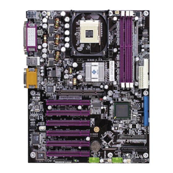
Page 10: Sy-P4I845Pe Motherboard Layout
Motherboard Description SY-P4I845PE 1-6 SY-P4I845PE MOTHERBOARD LAYOUT PS/2 Mouse PS/2 Mouse PS/2 KB Connector Connector COM A +12V Power COM B ATX Power USB 1_2 LAN Connector AOUT IDE 2 DDR1 DDR2 DDR3 AGP Slot AMIC DAVICOM DM9102AE AGAME PCI Slot #1 AC97 Audio CMOS Clear... -
Page 11: Sy-P4I845Pe Motherboard Components
Motherboard Description SY-P4I845PE 1-7 SY-P4I845PE MOTHERBOARD COMPONENTS F GH... -
Page 12: Atx Power Supply Connector
Motherboard Description SY-P4I845PE A +12V Power Connector CPU Cooling Fan1 Connector C Davicom Lan Chip D AGP Slot Socket 478 Connector Intel 845PE North Bridge Chip G CPU FSB setting Jumper H CPU Cooling Fan2 Connector DDR DIMM Bank CMOS Clear Jumper K Intel 82801DB South Bridge Chip ATX Power Supply Connector M Bus Mastering EIDE/ATAPI Ports... -
Page 13: Chapter 2 Hardware Installation
Hardware Installation SY-P4I845PE Chapter 2 HARDWARE INSTALLATION Congratulations on your purchase of SY-P4I845PE Motherboard. You are about to install and connect your new Motherboard. Note: Do not unpack the Motherboard from its protective anti-static packaging until you have made the following preparations. -
Page 14: Step 1 Install The Cpu
Hardware Installation SY-P4I845PE Step3- Install expansion cards. Step4- Connect cables, case wires, and power supply. Step5- Power on and enter BIOS setup . Step6- Install supporting software tools. See Chapter 4 for more info. Warning: Turn off the power to the Motherboard, system chassis, and peripheral devices before performing any work on the Motherboard or system. - Page 15 Hardware Installation SY-P4I845PE 2. Align the blunt edge of the CPU with the matching pinhole distinctive edge on the socket. 3. Seat the processor in the socket completely and without forcing.
-
Page 16: Cpu Fan Installation
Hardware Installation SY-P4I845PE 4. Then close the socket handle to secure the CPU in place. Remember to connect the CPU Cooling Fan to the appropriate power connector on the Motherboard. The fan is a key component that will ensure system stability. The fan prevents overheating, therefore prolonging the life of your CPU. -
Page 17: Step 2 Install Memory Module
Hardware Installation SY-P4I845PE Step 2 Install Memory Module DDR1 DDR2 DDR3 This motherboard support PC2100 and PC2700, Non-ECC and non-registered module. The largest memory capacity possible is 2GB. On this motherboard, DRAM speed can be set independent from the CPU front side bus speed. -
Page 18: Install Expansion Cards
Hardware Installation SY-P4I845PE Memory Configuration Table DDR1 DDR2 DDR3 Double sided Double sided None Double sided Single sided None Double sided Single sided Single sided Single sided Single sided none Note: 533MHz FSB CPU should be used to have PC2700 support. Step 3 Connect cables, case wires, and power supply Install expansion cards This section tells how to connect internal peripherals and the power supply... - Page 19 Hardware Installation SY-P4I845PE Step 5 Connect cables, case wire, and power supply A. IDE Device Installation (HDD, CD-ROM) IDE2 Secondary Pin1 IDE1 Primary IDE 3 This Motherboard offers two primary and one secondary IDE device connectors (IDE1, IDE2), can support up to four high-speed Ultra DMA 33/66/100HDD or CD-ROM.
- Page 20 Hardware Installation SY-P4I845PE 80-Conductor ATA 66/100 Flat Cable 40-pin...
- Page 21 Hardware Installation SY-P4I845PE B. Floppy Drive Installation Floppy Drive Connector Pin1 The system supports 5 possible floppy drive types: 720 KB, 1.2 MB, 1.44 MB, 2.88 MB. In addition, this Motherboard supports a 3-mode (720KB/1.2MB/1.44MB) floppy commonly used in Japan. Connect one side of the 34-pin flat cable to the floppy drive and plug the other end to the floppy drive connector on the Motherboard.
- Page 22 Hardware Installation SY-P4I845PE C. Front Panel Connections Speaker Power LED KeyLock Reset ACPI LED HDD LED PWRBT Plug the computer case's front panel devices to the corresponding headers on the Motherboard. 1. Power LED & KeyLock Plug the Power LED cable into the 5-pin Keylock header. Some systems may feature a KeyLock function with a front panel switch for enabling or disabling the keyboard.
- Page 23 Hardware Installation SY-P4I845PE 2. Reset Plug the Reset push-button cable into the 2-pin Reset header on the Motherboard. Pushing the Reset button on the front panel will cause the system to restart the boot-up sequence. Reset Pin Assignment Pin1 Pin2 Control PIN 3.
- Page 24 Hardware Installation SY-P4I845PE 5. IDE LED Attach the 2-pin IDE device LED cable to the corresponding IDE LED header on the Motherboard. This will cause the LED to lighten when an IDE1 or IDE2 (HDD, CD-ROM) device is active. HDD LED Pin Assignment Pin9 Pin10 LED Cathode...
- Page 25 Hardware Installation SY-P4I845PE D. Back Panel Connections All external devices such as the PS/2 keyboard, PS/2 mouse, printer, modem, USB can be plugged directly onto the Motherboard back panel. Only after you have fixed and locked the Motherboard to the computer case can you start connecting the external peripheral devices.
- Page 26 Hardware Installation SY-P4I845PE 1. Onboard Serial Ports COM1/COM2 External peripherals that use serial transmission scheme include: - serial mouse, - modem. Plug the serial device cables directly into the COMA/COMB 9-pin male connectors located at the rear panel of the Motherboard. 2.
- Page 27 Hardware Installation SY-P4I845PE 5. Universal Serial Bus (USB20_0, USB20_1) This Motherboard provides three USB ports for your additional devices. Plug the USB device jack into the available USB connector USB20_0. - Standard device drivers come with the operating system for commonly used USB devices.
- Page 28 Hardware Installation SY-P4I845PE E. Other Connections 1. Standard Infrared (SIRCON) Plug the 5-pin infrared device cable to the SIRCON header. This will enable the infrared transfer function. This Motherboard meets both the ASKIR and HPSIR specifications. Please install according to the following pin assignment: Standard Infrared (SIRCON) Connector SIRCON Pin Assignment...
- Page 29 Hardware Installation SY-P4I845PE 2. Cooling Fan Installation (1) CPU Cooling Fan (CPUFAN1, CPUFAN2) After you have seated the CPU properly on the processor, attach the 3-pin fan cable to the CPUFAN connector on the Motherboard. To avoid damage to the system, install according to the following pin assignment: CPU Cooling Fan (CPUFAN1, CPUFAN2)
- Page 30 Hardware Installation SY-P4I845PE (2) Chassis Cooling Fan (CHAFAN1, CHAFAN2) Some chassis also feature a cooling fan. This Motherboard features a CHAFAN connector to provide 12V power to the chassis fan. Connect the cable from the chassis fan to the CHAFAN 3-pin connector. Install according to the following pin assignment: Classis Cooling Fan (CHAFAN1, CHAFAN2)
- Page 31 Hardware Installation SY-P4I845PE 3. Smart Card Reader 4. CD Line-in (CDIN1) This Motherboard provides one CD-Line in connectors. Please connect the 4-pin audio cable from your CD-ROM drive to either CDIN1. Please install according to the following pin assignment: CDIN1(CD Line-in) Pin Assigment Left Right...
- Page 32 Hardware Installation SY-P4I845PE 4. AUX-IN (AUXIN1) This Motherboard provides one AUX-IN connectors. Please connect the 4-pin audio cable from your CD-ROM drive to either AUX-IN. Please install according to the following pin assignment: AUXIN1 Pin Assigment Left Right 5. MIC & LED Connector (J30) MIC &...
-
Page 33: Atx Power
Hardware Installation SY-P4I845PE F. ATX12V Power Supply The ATX12V power supply includes a 20-pin ATX connector that comply with the ATX specification, Version 2.03 for M/B specification, a new 4-pin receptacle/header combination--the +12V power connector--has been defined. The presence of the +12V power connector indicates that a power supply is ATX12V;... - Page 34 Hardware Installation SY-P4I845PE The Motherboard requires a power supply with at least 350 Watts and a "power good" signal. Make sure the ATX power supply can take at 1.5 A max current * load on the 5V Standby lead (5VSB) to meet the standard ATX specification.
- Page 35 Hardware Installation SY-P4I845PE G. CMOS Clear (JP5) In some cases the CMOS memory may contain wrong data, follow the steps below to clear the CMOS memory. 1. Clear the CMOS memory by momentarily shorting pin 2-3 on jumper JP5. This jumper can be easily identified by its white colored cap. 2.
- Page 36 Hardware Installation SY-P4I845PE Audio Upgrade The standard configuration of the P4I845PE motherboard supports 2 or 4-channel audio. Step 5 Power On You have now completed the hardware installation of your Motherboard successfully. 1. Turn the power on 2. To enter the BIOS Setup Utility, press the <DEL> key while the system is performing the diagnostic checks, Note: If you have failed to enter the BIOS, wait until the boot up sequence is completed.
-
Page 37: Quick Bios Setup
This Motherboard does not use any hardware jumpers to set the CPU frequency. Instead, CPU settings are software configurable with the BIOS [SOYO COMBO FEATURE]. The [SOYO COMBO FEATURE] combines the main parameters that you need to configure, all in one menu, for a quick setup in BIOS. - Page 38 Hardware Installation SY-P4I845PE prompt to load the BIOS optimal setup. Select [SOYO COMBO FEATURE] Step3. Do this step if you want to change or overclock the CPU FSB. Set the [CPU Frequency Select] field to “Manual”, to be able to change the CPU frequency 1 MHz stepping.
-
Page 39: Chapter 3 Bios Setup Utility
2. After the diagnostic checks, press the [Del] key to enter the Award BIOS Setup Utility. CMOS Setup Utility – Copyright ( C ) 1984-2002 Award Software SOYO COMBO Feature PC Health Status Standard CMOS Features Load Fail - Safe Defaults... - Page 40 BIOS Setup Utility SY-P4I845PE Hot Keys: Function keys give you access to a group of commands throughout the BIOS utility. Function Command Description Gives the list of options available for each General Help item. Previous Restore the old values. These are the values Values that the user started the current session with.
-
Page 41: Bios Setup Utility
BIOS Setup Utility SY-P4I845PE SAVE AND EXIT SETUP Select the [SAVE & EXIT SETUP] option from the Main Menu to save data to CMOS and exit the setup utility. This option saves all your changes and causes the system to reboot. R O M P C I / I S A B I O S... -
Page 42: Soyo Combo Setup
<DEL> key during the system diagnostic checks to enter the Award BIOS Setup program. The CMOS SETUP UTILITY will display on screen. Then, select the [SOYO COMBO Feature] option from the main menu and press the <Enter> key. - Page 43 BIOS Setup Utility SY-P4I845PE The [SOYO COMBO Feature] menu combines the main parameters that you need to configure, all in one menu, for a quick setup in BIOS. 3-1.1 System Performance Setting Description Note Adjust your system’s memory timing. Default...
- Page 44 BIOS Setup Utility SY-P4I845PE Setting Description Note Auto Detect Disabled Disables any clock signals on not Default PCI Clk used PCI slots. For EMI purposes. Enabled Disabled Modulates the clock signal on the Default Spread Spectrum CPU. For EMI purposes. 0.35% 0.50% 0.75%...
- Page 45 BIOS Setup Utility SY-P4I845PE 3-1.3 Advanced DRAM Control Setting Description Note DRAM Timing By SPD If enable the DRAM will auto Default detect the DRAM timing. Selectable Manual This item allows you to control CAS Latency Time the DRAM CAS Latency time. Default Active to This item allows you to control...
- Page 46 BIOS Setup Utility SY-P4I845PE 3-1.5 Onboard Settings Setting Description Note C.I.H. 4-WAY Enabled This item allows you Protection write-protect your BIOS chip from virus. If you want to flash your BIOS, set this option to disabled Disabled Default Enabled This item allow you to control Default Onboard IDE Onboard IDE RAID.
-
Page 47: Standard Cmos Setup
BIOS Setup Utility SY-P4I845PE 3-2 STANDARD CMOS SETUP Select the [STANDARD CMOS SETUP] option from the Main Menu and press [Enter] key. CMOS Setup Utility – Copyright ( C ) 1984-2002 Award Software Standard CMOS Features Date (mm:dd:yy) Mon, May 7 2001 Item Help Time (hh:mm:ss) 2 : 30 : 20... - Page 48 BIOS Setup Utility SY-P4I845PE 3-2.2 Hard Disks Type & Mode Choose the type and mode for the hard disks that you have already installed. Primary Setting Description Note (Secondary) Master & Slave IDE HDD Press To auto-detect the HDD’s size, Auto-Detection Enter head…...
- Page 49 BIOS Setup Utility SY-P4I845PE 3-2.4 Others Optional Setting Description Note EGA/VGA Select the video mode. Default Video CGA 40 CGA 80 MONO (Monochrome) ALL Errors When the BIOS detects system Default Halt On errors, this function will stop the No Errors system.
-
Page 50: Advanced Bios Features
BIOS Setup Utility SY-P4I845PE 3-3 ADVANCED BIOS FEATURES Select the [Advanced BIOS Features] option from the Main Menu and press [Enter] key. CMOS Setup Utility – Copyright ( C ) 1984-2002 Award Software Advanced BIOS Features Virus Warning Disabled Item Help CPU L1 &... - Page 51 BIOS Setup Utility SY-P4I845PE 3-3.1 Virus Warning Setting Description Note Disabled Allows you to choose the Default Virus Warning VIRUS warning feature for Enabled IDE Hard Disk boot sector protection. If this function is enabled and someone attempt to write data into this area, BIOS will show a warning message on screen and alarm beep.
- Page 52 BIOS Setup Utility SY-P4I845PE 3-3.4 Boot Up Floppy Seek Setting Description Note Disabled Seeks disk drives during boot up. Boot Up Floppy Seek Disabling speeds boot up. Enabled Default 3-3.5 Boot Up NumLock Status Setting Description Note Puts numeric keypad in Default Boot Up NumLock mode at boot-up.
-
Page 53: Security Option
BIOS Setup Utility SY-P4I845PE Typematic Settings Setting Description Note 6 (Char/sec) Choose the rate at which a Default Typematic Rate 8 (Char/sec) character is repeated when 10 (Char/sec) holding down a key. 12 (Char/sec) 15 (Char/sec) 20 (Char/sec) 24 (Char/sec) 30 (Char/sec) Typematic Delay 250 (msec) - Page 54 Default your FDD, whether it is disabled or not. Small Logo(EPA) Show Setting Description Note EPA LOGO LOG0 Allows user to display SOYO Default SELECT logo or own logo. Logo-0 shows LOG1 SOYO logo, Logo-1 shows user logo. Small Disabled Set Enabled to Show Logo(EPA).
-
Page 55: Advanced Chipset Features
BIOS Setup Utility SY-P4I845PE 3-4 ADVANCED CHIPSET FEATURES Caution: Change these settings only if you are already familiar with the Chipset. The [Advanced Chipset Features] option changes the values of the chipset registers. These registers control the system options in the computer. CMOS Setup Utility –... - Page 56 BIOS Setup Utility SY-P4I845PE 3-4.1 CHIPSET FEATURES SETUP CHIPSET Setting Description Note FEATURES System BIOS Disabled Cacheable Enabled The ROM area F0000H-FFFFFH is Default cacheable. Video BIOS Disabled Cacheable Enabled The video BIOS C0000H-C7FFFH is Default cacheable. Disabled This item allows you to control Delay Default Delayed Transaction...
-
Page 57: Integrated Peripherals
BIOS Setup Utility SY-P4I845PE 3-5 INTEGRATED PERIPHERALS Caution: Change these settings only if you are already familiar with the Chipset. The [INTEGRATED PERIPHERALS] option changes the values of the chipset registers. These registers control the system options in the computer. The following screen shows setup default settings. - Page 58 BIOS Setup Utility SY-P4I845PE The following tables describe each field in the INTEGRATED PERIPHERALS Menu and provide instructions on how to configure the IDE controls, FDC controls, and the onboard serial and parallel ports. 3-5.1 IDE Device Controls IDE Controls Setting Description Note...
- Page 59 BIOS Setup Utility SY-P4I845PE 3-5.2 Keyboard Controls Keyboard Controls Setting Description Note Disabled USB Controller Enabled Select Enabled if your system Default contains a Universal Serial Bus (USB) controller and you have USB peripherals. Disabled Select Enabled if you have USB USB 2.0 Controller 2.0 peripherals.
- Page 60 BIOS Setup Utility SY-P4I845PE 3-5.4 Others Optional Setting Description Note POWER ON Password Enables you to wake-up the system by entering a password at Function the keyboard. Hot KEY You can wake-up the system by pressing the key combination of your choice (Ctrl-F1~F12).
- Page 61 BIOS Setup Utility SY-P4I845PE 3-5.6 Onboard Serial Ports Onboard Serial Setting Description Note Ports Disabled Onboard Serial Port 1 / 3F8/IRQ4 Choose serial port 1 & 2's I/O Default Serial Port 2 address. (port 1) Do not set port 1 & 2 to the 2F8/IRQ3 Default same setting except for Disabled...
- Page 62 BIOS Setup Utility SY-P4I845PE 3-5.8 Others Optional Setting Description Note The system will switch on PWRON After PWR-Fail when power comes back after a power failure. The system will remain off Default when power comes back after a power failure. Former-Sts The system will return to the state it was in before the...
-
Page 63: Power Management Setup
BIOS Setup Utility SY-P4I845PE 3-6 POWER MANAGEMENT SETUP The [POWER MANAGEMENT SETUP] sets the system's power saving functions. CMOS Setup Utility – Copyright ( C ) 1984-2002 Award Software Power Management Setup ACPI Suspend Type S1(POS) Item Help x Run VGABIOS if S3 Resume Auto Power Management User Define Video Off Method... - Page 64 BIOS Setup Utility SY-P4I845PE 3-6.1 Power Management Controls Power Setting Description Note Management Controls ACPI Suspend S1(POS) This item allows you select Default Type suspend mode. S3(STR) S1 & S3 Auto Some OS (win xp/2k) require Default VGABIOS if to load VGABIOS after resume S3 Resume from S3.
- Page 65 BIOS Setup Utility SY-P4I845PE Power Management Controls (Continued) Power Setting Description Note Management Controls HDD Power Disabled Default Down 1-15Min When the set time has Some older elapsed, BIOS sends a model HDDs command to the HDD to may not power down.
- Page 66 BIOS Setup Utility SY-P4I845PE 3-6.2 Reload Global Timer Events Power Down Setting Description Note & Resume Events IDE0, IDE1 Disabled Default Primary Enabled In effect, the system remains alert for anything which occurs to a Secondary device which is configured as Enabled.
-
Page 67: Pnp/Pci Configuration Setup
BIOS Setup Utility SY-P4I845PE 3-7 PNP/PCI CONFIGURATION SETUP This option sets the Motherboard's PCI Slots. CMOS Setup Utility – Copyright ( C ) 1984-2002 Award Software PnP/PCI Configurations Reset Configuration Data Disabled Item Help Resources Controlled By Auto (ESCD) Menu Level x IRQ Resources Press Enter Default is Disabled. -
Page 68: Pnp/Pci Configuration Controls
BIOS Setup Utility SY-P4I845PE 3-7.1 PNP/PCI Configuration Controls PNP/PCI Setting Description Note Controls Disabled Retain PnP configuration Default Reset data in BIOS. Configuration Data Enabled Reset PnP configuration data in BIOS. Manual BIOS does not manage PCI/ISA PnP Resources Controlled By card IRQ assignment. - Page 69 BIOS Setup Utility SY-P4I845PE PNP/PCI Configuration Setup (Continued) PNP/PCI Setting Description Note Setup Interrupt How to set the BIOS to release the IRQ to the PnP Interrupt pool: Line PnP / PCI configuration Integrated Peripherals IRQ 15 IRQ 15: PCI / ISA PnP On-Chip Secondary PCI IDE: disabled IRQ 14 IRQ 14: PCI / ISA PnP On-Chip Primary PCI IDE: disabled...
-
Page 70: Pc Health Status
BIOS Setup Utility SY-P4I845PE 3-8 PC HEALTH STATUS This option sets the Motherboard's PC Health Status. CMOS Setup Utility – Copyright ( C ) 1984-2002 Award Software PC Health Status Shutdown Temperature Disabled Item Help CPU Vcore 1.72 V 3.3V 3.21 V Menu Level 5.02 V... - Page 71 BIOS Setup Utility SY-P4I845PE 3-8.1 CPU Device Monitoring CPU Device Setting Description Note Monitoring Disabled This item allows you to set up Default Shutdown Temperature the CPU shutdown Temperature. 50°C/122°F, This item only effective under 55°C/131°F, Windows 98 ACPI mode. 60°C/140°F, 65°C/149°F, 75°C/167°F,...
-
Page 72: Load Fail-Safe Defaults
This option is recommended if you need to reset the system setup and to retrieve the old values. CMOS Setup Utility – Copyright ( C ) 1984-2002 Award Software SOYO COMBO Feature PC Health Status Standard CMOS Features... -
Page 73: Load Optimized Defaults
This option is recommended if you need to reset the system setup and to retrieve the old values. CMOS Setup Utility – Copyright ( C ) 1984-2002 Award Software SOYO COMBO Feature PC Health Status Standard CMOS Features... -
Page 74: Supervisor Password
BIOS Setup Utility SY-P4I845PE 3-11 SUPERVISOR PASSWORD Based on the setting you have made in the [Security Option] of the [Advanced BIOS Feature] section, the password prevents access to the system or the setup program by unauthorized users. Follow this procedure to set a new password or disable the password: Choose [Advanced BIOS Feature] in the Main Menu and press [Enter]. -
Page 75: User Password
BIOS Setup Utility SY-P4I845PE Enter your new password and press [Enter]. The following message appears, prompting to confirm the new password: Confirm Password: Re-enter your password and then press [Enter] to exit to the Main Menu. This diagram outlines the password selection procedure: Type the Password Press <Enter>... -
Page 76: Boot Menu
BIOS Setup Utility SY-P4I845PE Boot Menu Boot Menu enables user to boot-up on different boot device without going into the BIOS setup. To enable boot Menu, press “ESC” after memory initialization, user will see a device menu, in which user can choose on which device they wish to boot from. -
Page 77: Chapter 4 Drivers Installation
Step 1. Insert the SOYO CD into the CD-ROM drive If you use Windows NT or 2000, the SOYO-CD will not detect your motherboard type. In that case the following dialog will pop up, please choose your motherboard and press OK. Now the SOYO-CD Start Up Menu will be shown. - Page 78 Drivers installation SY-P4I845PE The user's manual files included on the SOYO CD are in PDF (Postscript Document Format). In order to read a PDF file, the appropriate Acrobat Reader software must be installed in your system. Note: The Start Up program automatically detects if the Acrobat Reader utility is already present in your system, and otherwise prompts you on whether or not you want to install it.
- Page 79 Drivers installation SY-P4I845PE Step 2. Install Drivers and Utilities Drivers that are needed to install for the system to operate properly 1. Intel Chipset Software Installation Utility for Win 98/98SE/ME/NT/XP C-Media 8738 audio driver 3. HighPoint Utility for the on-board RAID function The rest of the available driver is optional.
- Page 80 Drivers installation SY-P4I845PE the IDE sub-system and overall system performance. Several components will be available only on Pentium(R) 4 processor-based systems running Microsoft Windows 2000 Professional. Software installation is flexible and fully automated for Microsoft Windows 98, Windows 98 Second Edition(SE),Windows 98 Millennium Edition(Me), Windows NT4.0, and Windows 2000 operating systems.
- Page 81 Step 3. Check the Latest Releases Click the 'Check the latest Releases' button to go the SOYO Website to automatically find the latest BIOS, manual and driver releases for your motherboard. This button will only work if your computer is connected to the internet through a network or modem connection.
- Page 82 Drivers installation SY-P4I845PE After Windows XP installation, your device manager should look like this:...
- Page 83 Drivers installation SY-P4I845PE After driver installation, your Windows XP device manager should look like this: Note: To install the USB 2.0 driver, please update to Windows XP service pack 1...
- Page 84 Drivers installation SY-P4I845PE Drivers directory list in the CD driver...
-
Page 85: Davicom Onboard Lan Driver Installaiton
6. Click on “Update Driver”. 7. Click on “Next”. 8. Select the following directory. 9. The directory is in SOYO CD “d:\LAN\Davicom” (where D: is your CD-ROM) then click ok you will need the windows 98 Second Edition CD to complete the installation. -
Page 86: Windows 2000
Davicom Onboard LAN Driver SY-P4I845PE 8. Select the following directory. 9. The directory is in SOYO CD:” D:\LAN\Davicom” (where D: is your CD-ROM) and click ok. 10. After informing windows of the driver directory the driver will be installed Restart your system after installation. - Page 87 7. Click “Update Driver”. 8. Select “Install from a list or specific location”, click it. 9. Click on “Next”. 10. Click “Browse”. 11. The LAN driver directory on the SOYO CD is “d:\LAN\Davicom” (where D: is your CD-ROM), then press “ok”.
-
Page 88: Chapter 6 Usb 2.0 Driver Installation
USB 2.0 Driver Installation SY-P4I845PE Chapter 6 USB 2.0 DRIVER INSTALLATION For Windows 2000 and Windows XP USB 2.0 Drivers are available for download using Windows Update for both Windows XP and Windows 2000. For additional information regarding USB 2.0 support in Windows XP and Windows 2000, please visit http://www.microsoft.com/hwdev/bus/USB/default.asp... -
Page 89: Chapter 7 Highpoint Hpt 371 Driver Installation
Next continue. 6. A dialog box will pop up, input the path of the SOYO CD. D:\Raid\Hpt371\121\Win98_ME. (Where D: is your CDROM drive) Then click to continue. 7. In the next window, the driver you need to install will appear,... - Page 90 HighPoint hpt371 Driver Installation SY-P4I845PE button. 3. In the next window, select Have Disk..4. Insert the SOYO driver CD and type in the path the driver CD of D:\Raid\Hpt371\121\WinNT, then click HPT371 UDMA/ATA133 5. In the next window, select the Controller item, then click Follow the system prompt to install the driver.
- Page 91 HighPoint hpt371 Driver Installation SY-P4I845PE 6. Check “search removable media …..” and then click next 7. Choose the driver for Win XP 8. During installation, Win XP will prompt you to insert the RAID driver diskette 9. Browse to the directory that contains the missing file (D:\raid\hpt371\121\Winxp).
- Page 92 HighPoint hpt371 Driver Installation SY-P4I845PE NT4.0. Install driver during Windows 2000 installation 1. Go to “D:\raid\hpt371\121\” directory, (assuming that your CD-ROM is drive d) copy all the files and directories to a floppy disk. 2. If Windows 2000 is installed from the floppy drive, please let the installing program run automatically.
- Page 93 HighPoint hpt371 Driver Installation SY-P4I845PE the F6 Key. 3. Press the key to specify additional devices when the Windows XP Setup window appears. 4. The system will ask whether to install the driver under WinNT Windows XP, please select to install the or under driver under Windows XP.
-
Page 94: Chapter 8 Serial-Ata Driver Installation
Serial-ATA Driver Installation SY-P4I845PE Chapter 8 SERIAL-ATA DRIVER INSTALLATION Win 98SE/2000/XP installation The Serial-ATA chip will be automatically detected after installing the Highpoint 371 driver.
Need help?
Do you have a question about the SY-P4I845PE and is the answer not in the manual?
Questions and answers