
Related Manuals for Steel City 55200


Summary of Contents for Steel City 55200
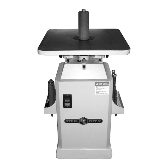
- Page 1 User Manual Read and understand this manual before using machine. OSCILLATING SPINDLE SANDER Model Number 55200 ® STEEL CITY TOOL WORKS Manual Part No. OR71235...
-
Page 3: Table Of Contents
TABLE OF CONTENTS INTRODUCTION SECTION 1 Warranty ..............................4 SECTION 2 Product Specifications ..........................7 SECTION 3 Accessories and Attachments ........................7 SECTION 4 Feature Identification ..........................8 SECTION 5 General Safety............................9 SECTION 6 Product Safety ............................11 SECTION 7 Electrical Requirements........................12 SECTION 8 Unpacking & Inventory..........................14 SECTION 9 Assembly ..............................15 SECTION 10... -
Page 4: Warranty
WARRANTY STEEL CITY TOOL WORKS 5 YEAR LIMITED WARRANTY Steel City Tool Works, LLC (“SCTW”) warrants all “STEEL CITY TOOL WORKS” machinery to be free of defects in workmanship and materials for a period of 5 years from the date of the original retail purchase by the original owner. - Page 5 WARRANTY CARD Name ________________________________________________ How would you rank your woodworking skills? Street _______________________________________________ ___ Simple ___ Intermediate Apt. No. ______________________________________________ ___ Advance ___ Master Craftsman City _________________________ State ______ Zip __________ Phone Number_________________________________________ How many Steel City machines do you own? _____________ E-Mail ________________________________________________ 10.
- Page 6 FOLD ON DOTTED LINE PLACE STAMP HERE Steel City Tool Works P.O. Box 10529 Murfreesboro, TN 37129 FOLD ON DOTTED LINE...
-
Page 7: Product Specifications
PRODUCT SPECIFICATIONS MOTOR PRODUCT DIMENSIONS Footprint 18-1/2” x 18-1/2” Type TEFC, Induction, Ball Bearing Length 18-1/2” Continuous Duty Width 18-1/2” Horsepower 1 HP Height 39” Amps 10/5 Weight 298 lbs. Voltage 115/230 SHIPPING DIMENSIONS Phase Single Carton Type Cardboard Hertz Length 25”... -
Page 8: Feature Identification
FEATURE IDENTIFICATION A) Table D) Spindle Trays (2) B) Sanding Drum E) START/STOP Switch C) Table Insert F) Table Tilting Lock Knobs (2) -
Page 9: General Safety
GENERAL SAFETY WARNING WARNING TO AVOID serious injury and damage to the machine, read and follow all Safety and Operating Instructions before assembling and operating this machine. This manual is not totally comprehensive. It does not Exposure to the dust created by power sanding, saw- and can not convey every possible safety and opera- ing, grinding, drilling and other construction activities tional problem which may arise while using this... - Page 10 11. DO NOT FORCE the machine to perform an opera- WARNING tion for which it was not designed. It will do a safer and higher quality job by only performing operations for which the machine was intended. 12. DO NOT stand on a machine. Serious injury could result if it tips over or you accidentally contact any 3.
-
Page 11: Product Safety
25. USE ONLY recommended accessories. Use of 3. Prevent electrical shock. Follow all electrical and incorrect or improper accessories could cause seri- safety codes, including the National Electrical Code ous injury to the operator and cause damage to the (NEC) and the Occupational Safety and Health machine. -
Page 12: Electrical Requirements
15. BE SURE that spindles are securely locked in the 26. INSPECT MATERIALS FOR DEFECTS. Knots and machine before starting. splinters can shoot from the machine with great force. Make sure defective materials are not used 16. DO NOT clear chips and dust when spindle is on the spindle sander. -
Page 13: Grounding Instructions
GROUNDING INSTRUCTIONS EXTENSION CORDS WARNING WARNING This machine MUST BE GROUNDED while in use to protect the operator from electric shock. To reduce the risk of fire or electrical shock, use the In the event of a malfunction or breakdown, GROUND- proper gauge of extension cord. -
Page 14: Unpacking & Inventory
UNPACKING & INVENTORY can be removed by spraying WD-40 on them and WARNING wiping it off with a soft cloth. This may need redone several times before all of the protective coatings are removed completely. After cleaning, apply a good quality paste wax to any unpainted surfaces. -
Page 15: Assembly
ASSEMBLY Assembly of the spindle sander is organized into steps. To remove the sanding spindle: Please follow them in sequence. Review the parts diagrams and lists frequently to become familiar with 1. Use your spindle wrench (A) provided with the all of the parts before you begin. -
Page 16: Table Inserts
D. SANDING SLEEVES WARNING To replace the sleeves: Failure to use the correct insert with the corre- sponding drum may result in injury! 1. Loosen the hex nut (A) at the top of the sanding spindle (B). SEE FIG. 3 Fig. -
Page 17: Adjustments
ADJUSTMENTS TABLE ANGLE 2. Lock the knobs down when your table is square to the sanding spindle. You can now calibrate the The angle adjustment knobs (A) enable the table top to angle indicator arrow (C) by loosening its retaining be tilted up to 45°. -
Page 18: Section 11 Operations
CHANGING MOTOR VOLTAGE Refer to “ELECTRICAL REQUIREMENTS” section before proceeding: WARNING 1. DISCONNECT THE MACHINE FROM THE POWER SOURCE. 2. Remove the switch box cover. 3. The motor has four leads. Reconnect the motor MAKE CERTAIN THE MACHINE IS DISCONNECTED leads for chosen voltage, as shown in the wire FROM THE POWER SOURCE. -
Page 19: Operations
OPERATIONS BEFORE STARTING YOUR SANDER FOR THE FIRST BEVEL SANDING TIME, CHECK OIL LEVEL AND GREASE POINTS. 1. Tilt the table to the angle of bevel you desire. See “MAINTENANCE” section for more information. Check oil level at least once per month. 2. -
Page 20: Maintenance
MAINTENANCE Gear Oil: Your Spindle Sander requires very little maintenance. Cleaning will increase the machine’s durability and Gear oil should be changed at 800 hours of use with a efficiency by removing grime which can gum up moving high-quality 90 Wt. SAE gear oil. The oil cap w/dipstick parts. -
Page 21: Troubleshooting
TROUBLESHOOTING GUIDE TO PREVENT INJURY TO YOURSELF or damage to the spindle sander, turn the switch to the OFF position and unplug the power cord from the electrical receptacle before making any adjustments. PROBLEM LIKELY CAUSE(S) SOLUTION Motor will not 1. -
Page 22: Parts List
PARTS... - Page 23 PART PART DESCRIPTION QTY. DESCRIPTION QTY. OR94117 Oil Seal OR71165 Power Cord OR94118 Retaining Ring OR94125 Strain Relief Bushing OR94119 Ball Bearing OR94126 Pan Head Screw OR94120 Retaining Ring OR71166 Rubber Foot OR71160 Motor Bracket OR90616 5/16”-18 Hex Nut OR94121 Lock Washer OR71167 Base...
- Page 25 PART PART DESCRIPTION QTY. DESCRIPTION QTY. OR71171 Oil Tank OR71185 Oil Cap OR71172 Oil Plug OR71186 Oil Tank Lid OR71173 Oil Level lndicator OR90369 3/8”-16 Hex Nut OR94131 Set Screw OR94139 3/8” -16 x 3/4”” Hex Soc Hd Set Screw OR71174 Shaft Coupler OR71187...
- Page 27 PART PART DESCRIPTION QTY. DESCRIPTION QTY. OR94146 Wrench OR71218 1” Washer OR71197 Table Insert (small) OR71219 1 1/2” Spindle Assy Const. Of Ref 241, 261, 262, 263, 243 OR71198 Table Insert (medium) OR71220 1-1/2” Rubber Drum OR71199 Table Insert (Large) OR71221 1 1/2”...
- Page 28 x NOTES x...
- Page 29 x NOTES x...
- Page 30 x NOTES x...
- Page 31 STEEL CITY TOOL WORKS www.steelcitytoolworks.com 1-877-SC4-TOOL (1-877-724-8665) 5 Year Warranty...
Need help?
Do you have a question about the 55200 and is the answer not in the manual?
Questions and answers