Table of Contents
Advertisement
Quick Links
Advertisement
Table of Contents

Related Manuals for Fugro 8200HP


Summary of Contents for Fugro 8200HP
-
Page 1: User Manual
OmniSTAR 8200HP User Manual Issue 1.07, October 2008... - Page 2 OmniSTAR 8200HP User Manual Notice to Customers This manual has been produced to ensure the very best performance from your OmniSTAR receiver. The manual has been clearly set out with simple instructions to ensure trouble free usage of your OmniSTAR receiver.
- Page 3 DB9 pin layout added Issue 1.07 October 2008 Modifications to pin layout Manual Reference: OmniSTAR 8200HP User Manual Copyright OmniSTAR B.V. 2007. No part of this manual can be reproduced without the express permission of OmniSTAR B.V. Issue 1.07, 10/2008...
-
Page 4: Table Of Contents
OmniSTAR 8200HP User Manual TABLE OF CONTENTS INTRODUCTION ..................... 2 ..................2 BOUT ANUAL ..................2 YSTEM EATURES ..................3 ECEIVER EATURES Housing ....................3 Accessories....................4 INSTALLATION AND SET UP ................ 6 ..............6 NSTALLATION ONSIDERATIONS (CEMF) ..........7... - Page 5 APPENDIX F ....................79 ..............79 ECEIVER ERVICE ROCEDURE APPENDIX G ....................80 STAR R ........... 80 ECEIVER ROBLEM EPORT USER NOTES ....................81 LIST OF FIGURES Figure 1: 8200HP Back End ................4 Figure 2: Z+ antenna ..................5 Issue 1.07, 10/2008...
- Page 6 OmniSTAR 8200HP User Manual Figure 3: Zener Diode Connected..............7 Figure 4: Multipath..................11 Figure 5: Home screen when OmniSTAR HP corrections are received ..14 Figure 6: Status screen ................. 17 Figure 7: Configuration screen............... 17 Figure 8: Contrast screen ................18 Figure 9: User level screen................
- Page 7 OmniSTAR 8200HP User Manual Figure 54: Receiver Options: VRS Processing ..........33 Figure 55: Receiver Options: Tilt Sensor ............33 Figure 56: Position error caused by a tilted, high-mounted receiver antenna . 33 Figure 57: Receiver Options: WAAS.............. 34 Figure 58: Receiver Options: CMR Input ............34 Figure 59: Receiver Options: Point/Line/Area ..........
- Page 8 Table 7: (D)GPS quality indicators..............49 Table 8: NMEA 2000 default message rates ..........53 Table 9: 8200HP Power/data Port Pin-Out Descriptions (both port A and B) . 57 Table 10: NMEA 0183 messages available for the 8200HP......58 Table 11: Description of the GGA message........... 59 Table 12: Description of the GLL message............
-
Page 9: Introduction
OmniSTAR 8200HP DGPS Receiver. System Features The OmniSTAR 8200HP DGPS Receiver is part of the OmniSTAR world-wide DGPS Service. The OmniSTAR service is a full-time differential GPS (DGPS) broadcast system delivering corrections from an array of GPS reference stations located around the globe. -
Page 10: Receiver Features
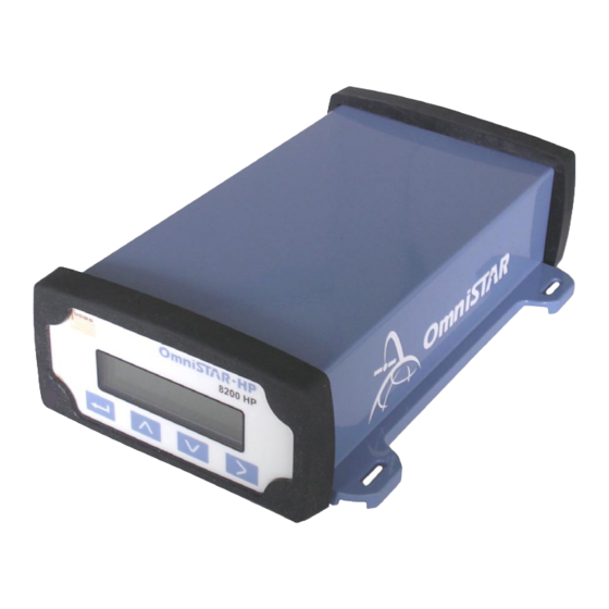
Housing The 8200HP is housed in an enclosure to provide a complete receiver solution. When connected to an antenna and a power source, the 8200HP is a fully functioning GPS/VBS/XP/HP receiver. The enclosure offers protection against environmental conditions and RF interference. -
Page 11: Accessories
OmniSTAR 8200HP User Manual Accessories The following accessories are included with the 8200HP: • 1 right angle combined power/data cable • 1 GPS antenna type Z Plus • 1 antenna cable (5 meters) • 1 magnetic antenna mount • A CD containing PC utilities and product documentation... -
Page 12: Figure 2: Z+ Antenna
OmniSTAR 8200HP User Manual Figure 2: Z+ antenna Issue 1.07, 10/2008... -
Page 13: Installation And Set Up
OmniSTAR 8200HP User Manual Installation and Set Up Installation Considerations Before commencing installation of the OmniSTAR 8200HP in a vehicle or aircraft, the following should be considered: • Determine the preferred location for each unit. Consider cable length, connector attachment space (cable bend radius), stowing excess cable, moisture, chemical corrosion, vibration and heat exposure. -
Page 14: Counter Electromagnetic Force (Cemf)
OmniSTAR 8200HP User Manual Counter Electromagnetic Force (CEMF) A potential problem inherent in any installation of electronic systems within a vehicle is Counter Electro-magnetic Force (CEMF). CEMF is caused when relays or solenoids, connected to the vehicle DC power distribution, are de-energised. The voltage produced may exceed – 400 volts. -
Page 15: Cable Installation
OmniSTAR 8200HP User Manual Cable Installation Cables must be correctly installed for optimum system operation. Therefore, the following should be noted: • Do not route an L-Band receiver remote antenna cable with the cabling of any other radio system. This may cause interference between both systems. -
Page 16: Features And Information
These signals are called strobes. Access to the 8200HP strobe signals can be obtained through both data ports. The strobe available on the 8200HP is the One Pulse Per Second (1 PPS) signal. The falling edge of this signal is synchronised with GPS time. -
Page 17: Antenna Location
Power Supply Requirements The 8200HP can be powered by a vehicle or by a customer-supplied power source of 10-32 VDC, capable of delivering at least 5W continuous output power. For continued protection against the risk of fire, the power lead to the 8200HP receiver should be provided with a 10 A (maximum) fuse. -
Page 18: Operating Considerations
OmniSTAR 8200HP User Manual Operating considerations The 8200HP has proven to be a high-quality positioning device. The accuracy that the user can obtain depends on several factors, including: • Number of visible satellites • Multipath • Dilution of Precision (DOP) •... -
Page 19: Position Dilution Of Precision (Pdop)
When interference levels are too high, the 8200HP may even lose lock to either the OmniSTAR satellite or the GPS satellites. Interference sources include radio and television transmitters, radars,... -
Page 20: Operation
Connect the power leads to a suitable (10-32 V DC) power supply. Getting Started The purpose of this section is to get you started with the 8200HP as quickly as possible. The guide will address receiving the satellite data carrier, and then checking the functionality and status of the HP Process. -
Page 21: The Receiver Home Screen
OmniSTAR 8200HP User Manual EHES (followed by a progress indicator bar on the second line of the display) Starting Up (followed by a progress indicator bar on the second line of the display) Launch[______GD] Launch[______HP] Launch[______CN] Launch[______Go] _____8200HP (C)1997-2003_TNL 8200HP... -
Page 22: Table 2: Position Types
OmniSTAR 8200HP User Manual EASAT: The receiver is using differential corrections broadcast by the EASAT satellite. The signal to noise ratio of the DGPS signal. Signal to noise values below 4 indicate an unusable signal, signal to noise values between 4 and 8 indicate a fair signal strength and signal to noise values higher than 8 indicate an excellent signal strength. -
Page 23: The 8200Hp Menu Structure
Table 3: Differential information The 8200HP menu structure The menu structure of the 8200HP consists of 3 top-level menu screens. Each top-level menu screen links to one or more sub-menu screens. Each sub- menu screen links sequentially to a number of information/configuration screens. -
Page 24: Top-Level: Home
OmniSTAR 8200HP User Manual left corner. To cycle through the underlying information screens, press repeatedly. This section of the manual will describe the 8200HP’s menu structure and screens. Top-level: home The home screen is the receiver’s default screen after a successful receiver boot. -
Page 25: Figure 8: Contrast Screen
OmniSTAR 8200HP User Manual Contrast Figure 8: Contrast screen Contrast is a configuration item. Using this screen, the contrast of the receiver’s LCD screen can be increased or decreased. Default value is 30. User Level Figure 9: User level screen User level is a configuration item. -
Page 26: Figure 11: Lock Display - Enter Password Screen
OmniSTAR 8200HP User Manual Figure 11: Lock Display - Enter Password screen The cursor blinks on the first digit. Enter the receiver password, which is equal to the last five digits of the serial number of your receiver. The value of the active digit can be changed by pressing . -
Page 27: Figure 14: Snr Units Screen
OmniSTAR 8200HP User Manual Figure 14: SNR Units screen The SNR Units screen is used to configure the units representing the signal to noise ratio of the received signal. Default is C/N0 (dB). The other option is AMU. Issue 1.07, 10/2008... -
Page 28: Figure 15: Clear Bb Ram Screen
Update Receiver Figure 16: Update Receiver screen It is possible to purchase options with the 8200HP receiver. To unlock these options, a password is required, which can be provided by your OmniSTAR reseller. Using the Update Receiver screen, the password can be entered. -
Page 29: Sub-Menu: Gps Status
Figure 20: GPS Speed and Heading screen The speed and heading screen shows current speed and heading with reference to true north of the vehicle carrying the 8200HP. When the 8200HP is used in static mode, the information in this screen has no meaning except for the status of the position solution. -
Page 30: Sub-Menu: Dgps Status
Figure 21: GPS Channel Status screen The GPS Channel status screen shows the status of all 12 receive channels of the 8200HP. The channels can be cycled by pressing repeatedly. The information shown (from left to right) is the receiver channel number, the... -
Page 31: Figure 23: Dgps Sat Tracking Screen
The DGPS Data Source screen shows the identification numbers of the OmniSTAR reference stations used to calculate the differential corrections for the 8200HP at its current location. To scroll through the list of reference stations, press repeatedly. Station ID 9999 indicates use of XP. -
Page 32: Figure 26: Age Of Dgps/Sync Screen
Figure 26: Age of DGPS/Sync screen The Age screen shows the age of the differential data (in seconds) and the time elapsed since the last valid differential correction received by the 8200HP (Age of Sync). Because it takes some time to calculate differential corrections at the reference station and broadcast these corrections to the 8200HP, the smallest DGPS age will always be a few seconds. -
Page 33: Figure 29: Vbs Info Screen: Stop
Figure 30: VBS Info screen: Received Data The Received Data screen shows whether or not the 8200HP has received all necessary information from the OmniSTAR satellite to calculate a VBS position. -
Page 34: Figure 33: Vbs Info Screen: Figure Of Merit
OmniSTAR 8200HP User Manual Figure 33: VBS Info screen: Figure of merit The Figure of Merit is a quality indicator. It shows the ratio of packages received with an invalid checksum and packages received with a valid checksum over the last couple of measurements The closer to 100%, the better. -
Page 35: Figure 37: Hp/Xp Info Screen: Stop
OmniSTAR 8200HP User Manual The Solution Convergence screen shows whether or not the HP/XP solution has already converged to within the set convergence limits (see also the corresponding configuration screen, described further on in this manual). Figure 37: HP/XP Info screen: Stop The Stop screen shows the expiration date of the current OmniSTAR subscription (mm/dd/yy format). -
Page 36: Figure 40: Hp/Xp Info Screen: Hp Version
OmniSTAR 8200HP User Manual Subs. Mode Description 000A 000B (converged) XP only mode 000C 0014 0016 (converged) HP only mode 0017 001E 001F HP/XP combined mode (HP 0020 0021 (converged) Table 4: XP/HP Subscription types Figure 40: HP/XP Info screen: HP version The HP version screen shows the HP firmware version currently loaded in the receiver. -
Page 37: Sub-Menu: Receiver Status
OmniSTAR 8200HP User Manual The second service ID screen, shown in Figure 42, shows the satellite uplink ID and initial vector for the US/Australia uplink. Sub-menu: Receiver Status In the Receiver Status menu, the following information items can be found. -
Page 38: Figure 46: Receiver Firmware Version
OmniSTAR 8200HP User Manual Firmware Version Figure 46: Receiver firmware version The Firmware version screen shows the receiver firmware currently loaded in the receiver and the date this particular firmware version was released. Receiver Options The Receiver Options screen consists of 13 different information screens, that can be cycled through by pressing repeatedly. -
Page 39: Figure 49: Receiver Options: Everest Multipath Rejection
OmniSTAR 8200HP User Manual Figure 49: Receiver Options: Everest Multipath Rejection The Everest MPR screen shows whether the Everest Multipath Rejection technology is implemented in the receiver. Figure 50: Receiver Options: Modem Control The Modem Control screen indicates whether or not one of the communication ports has been configured to use the RTS/CTS signals in communication with a connected device. -
Page 40: Figure 54: Receiver Options: Vrs Processing
OmniSTAR 8200HP User Manual The Carrier Phase screen shows whether or not the receiver is capable of processing carrier phase differential corrections broadcast by an RTK base station. Figure 54: Receiver Options: VRS Processing The VRS (Virtual Reference Station) option allows the user to operate the receiver within an RTK network. -
Page 41: Figure 57: Receiver Options: Waas
OmniSTAR 8200HP User Manual Figure 57: Receiver Options: WAAS The WAAS screen shows whether or not the receiver is capable of receiving and processing WAAS, MSAS and EGNOS signals and whether or not the receiver is currently using either WAAS, MSAS or EGNOS corrections. -
Page 42: Figure 61: System Voltages
OmniSTAR 8200HP User Manual System Voltages Figure 61: System voltages The System Voltages screen shows the current power supply voltage of the receiver. System Temp Figure 62: System temperature The System Temp screen shows the current temperature inside the receiver case. -
Page 43: Sub-Menu: Can Status
ChA TPCAN Conns Figure 66: Channel A TPCAN Connections The TPCAN connections screen shows a list of other devices connected to the same CAN bus as the 8200HP on channel A. To cycle through the different Issue 1.07, 10/2008... -
Page 44: Sub-Menu: Gps Config
OmniSTAR 8200HP User Manual screens (when more devices are connected than can be listed on one screen), press repeatedly. ChB TPCAN Conns Figure 67: Channel B TPCAN Connections As above, but for the second communication port. Sub-menu: GPS Config In the GPS Config menu, the following configuration items can be found. Items are listed in order, cycling through items can be done by pressing the buttons. -
Page 45: Figure 70: System Masks
Mask values and 2D-3D values both lie between 1 and 99. Keep in mind that only a mask value larger than the current 2D-3D value makes sense if the 8200HP is to show ‘graceful degradation’ of the position solution (i.e. 3D – 2D – no position solution). -
Page 46: Figure 72: Position Filter
By default, the position filter is set to PV, normal level and no filtering. CC Filter Figure 73: Carrier Code Filter The 8200HP can use the GPS carrier information to remove noise from the code information, thus improving system performance. Options for the C.C. filter are ‘Reset Filt(New)’ and ‘Propagate (Old)’. -
Page 47: Sub-Menu: Dgps Config
OmniSTAR 8200HP User Manual configured to output the NMEA/TSIP messages at a higher rate (see page 48 of this manual). Default setting of the position rate is 1 Hz. Dynamic Mode Figure 75: Dynamic Mode The receiver can be configured for use in different dynamic modes. Each dynamic mode directly influences the filter settings (see also page 39 of this manual). -
Page 48: Figure 78: Dgps Backup Source Select
Valid range is 0 to 250 seconds, with 250 seconds being the default value. If the last received differential signal is older than the preset age limit, the 8200HP will revert to calculating and outputting a ‘plain’ GPS position. -
Page 49: Figure 80: Ez Sat
The EZ Sat screen is used to easily select an OmniSTAR satellite. Instead of having to look up and enter satellite frequencies manually, just select the appropriate OmniSTAR satellite from a list or let the 8200HP search for the strongest available signal from the OmniSTAR satellites currently in view. -
Page 50: Figure 83: Hp/Xp Autoseed
HP/XP Autoseed Figure 83: HP/XP Autoseed When the 8200HP loses HP/XP lock, getting a new converged HP/XP position after regaining a lock can take quite some time. Seeding the receiver (i.e. input the approximate position and estimated position uncertainties) will reduce the time needed for HP/XP convergence considerably. -
Page 51: Sub-Menu: Port A Config
Figure 85: HP/XP Convergence limit Using the HP/XP Converge screen, the convergence limit for an HP/XP solution can be set. The 8200HP will report a converged HP/XP position when the estimated position error is less than the value set in this screen. Default value is 30 cm / 12 inches. -
Page 52: Table 5: 8200Hp Input Protocols
See the description for the TEXTA setting (above). None Inputs nothing to the receiver Table 5: 8200HP input protocols Although TEXTA and TEXTB can be selected as input protocol, the TEXTA and TEXTB functions appear not to have been implemented in firmware versions 3.10 to 3.56. -
Page 53: Figure 88: Port-A Modem Control Options
OMNIHP port. None Outputs nothing from the receiver Table 6: 8200HP output protocols Port A Out RTS/CTS Figure 88: Port-A Modem control options The RTS/CTS screen can be used to toggle between using or not using the RTS and CTS signals through the communication port. Some external devices, like modems, need RTS and CTS signals for their correct functioning. -
Page 54: Figure 89: Nmea Messages 1
8200HP. Messages set in lower case are not output, messages set in upper case are output when the output protocol is set to NMEA. The 8200HP is capable of outputting a number of NMEA messages, that may not all be needed as inputs for the attached device. -
Page 55: Figure 90: Nmea Messages 2
OmniSTAR 8200HP User Manual NMEA2 Messages Figure 90: NMEA messages 2 The second NMEA messages screen is essentially the same as the first, only different messages can be selected. NMEA3 Messages Figure 91: NMEA messages 3 The third NMEA messages screen is also equivalent to the first and second one, again presenting more different messages to be selected for output. -
Page 56: Sub-Menu: Port B Config
NMEA/TSIP output rates screen. Messages displayed in upper case are output at a 1 Hz rate, messages displayed in lower case are not. The current versions of the 8200HP firmware only support setting the VTG message to 1 Hz. NMEA Quality... -
Page 57: Sub-Menu: Port C Config
Port B In/Out Figure 95: Port B I/O configuration settings Although the 8200HP features three communication ports, there are only two physical communication ports on the receiver back panel. In order to be able to use all three communication ports, port B and port C are both connected to physical power/data port B of the receiver. -
Page 58: Figure 97: Can-Bus Baudrate Setting
OmniSTAR 8200HP User Manual In the CAN A Config menu, the following configuration items can be found. Items are listed in order, cycling through items can be done by pressing the buttons. Selecting the item to change is done by pressing the button (repeatedly, if necessary). -
Page 59: Figure 100: Can-Bus Message Rates
OmniSTAR 8200HP User Manual The CAN messages screen is used to control the output messages from the receiver. Messages displayed in upper case are output, messages displayed in lower case are not. Default, all three J1939 messages are active. CAN Msg Rate... -
Page 60: Figure 103: Nmea 2000 Message Rates
OmniSTAR 8200HP User Manual NMEA 2000 Msg Rate Figure 103: NMEA 2000 message rates The NMEA 2000 Msg Rate configuration controls the message rate of each NMEA 2000 message output to the CAN bus. It is similar to the CAN bus message rates configuration. -
Page 61: Figure 105: Can-Bus Self-Configured Address
OmniSTAR 8200HP User Manual Self CFG Address Figure 105: CAN-bus self-configured address Devices on a CAN bus can be configured to either get an address automatically, or try to use a preset address and revert to another address should the preset address already exist on the bus. Default is trying to use the preset address. -
Page 62: Technical Specifications
OmniSTAR 8200HP User Manual Appendix A Technical Specifications Performance Position Accuracy VBS: 0.78 m 2DRMS 0.10 m 2DRMS 0.20 m 2DRMS Reacquisition <5 s L1 (typical) <5 s L2 (typical) Data Rates 1, 5, 10 Hz Time Accuracy 20 ns RMS Velocity Accuracy 0.05 m/s RMS... -
Page 63: Power Requirements
OmniSTAR 8200HP User Manual Power requirements Voltage +10 to +32 VDC Power consumption 4.2 W (typical) RF input / LNA power output Antenna connector TNC female, 50 nominal impedance RF Input Frequencies 1575.42 MHz (L1), 1227.60 MHz (L2), 1525 MHz – 1559 MHz (L-Band) -
Page 64: Figure 106: Pin Layout (Receiver Connector)
Negative voltage lead 1 PPS output 9 (blue) Table 9: 8200HP Power/data Port Pin-Out Descriptions (both port A and B) Figure 106: Pin layout (receiver connector) Pins 7 and 10 of Port A are jumpered with a 5 kOhm, 5% resistor. -
Page 65: Appendix B
Appendix B NMEA 0183 Message Options The OmniSTAR 8200HP is configured to output 4 NMEA 0183 sentences (GGA, GSA, RMC and VTG) by default. Sentences can be added or removed by the user using the NMEA configuration screens (see page 47). The default output rate is set to 1 Hz, but 5 and 10 Hz may also be selected. -
Page 66: Nmea 0183 Message Formats
OmniSTAR 8200HP User Manual NMEA 0183 Message Formats In this section each message is described in more detail. – GPS Fix Data The GGA message includes time, position and fix related data for the GPS receiver. $GPGGA,hhmmss.ss,ddmm.mmmmm,D,dddmm.mmmmm,D,Q,sv,H.H,h.hh, M,h.hh,M,A.AA,DRID*XX Field Number... -
Page 67: Gll - Geographic Position - Latitude/Longitude
OmniSTAR 8200HP User Manual - Geographic Position – Latitude/Longitude The GLL message contains the latitude and longitude of the present position, the time of the position fix and its status. $GPGLL,ddmm.mmmmmmm,D,dddmm.mmmmmmm,D,hhmmss.ss,A*XX Field Number Description Latitude, N (North) or S (South). -
Page 68: Gsa - Gps Dop And Active Satellites
OmniSTAR 8200HP User Manual – GPS DOP and Active Satellites The GSA message indicates the GPS receivers operating mode and lists the satellites used for navigation and the DOP values of the position solution. $GPGSA,m,f,sv,sv,sv,sv,sv,sv,sv,sv,sv,sv,sv,sv,P.P,H.H,V.V*XX Field Number Description Mode: M = Manual, A = Automatic. -
Page 69: Gst - Gps Pseudorange Noise Statistics
OmniSTAR 8200HP User Manual – GPS Pseudorange Noise Statistics The GST message is used to support Receiver Autonomous Integrity Monitoring (RAIM). $GPGST,hhmmss.ss,S.S,M.M,m.m,ddd.d,y.y,x.x,h.h,*XX Field Number Description UTC time of GGA fix RMS value of the standard deviation of the range inputs to the navigation process (range inputs... -
Page 70: Gsv - Gps Satellites In View
OmniSTAR 8200HP User Manual – GPS Satellites in View The GSV message identifies the number of SVs in view, the PRN numbers, elevation, azimuth and SNR values. $GPGSV,M,S,T,sv,el,azm,snr,sv,el,azm,snr,sv,el,azm,snr,sv,el,azm,snr*XX Field Number Description Total number of sentences of this type in this... -
Page 71: Mss - Beacon Receiver Signal Status
OmniSTAR 8200HP User Manual – Beacon Receiver Signal Status The MSS message identifies the status of the beacon signal, including the beacon signal strength, beacon signal-to-noise ratio (SNR), beacon frequency and beacon bit rate. $GPMSS,SS.S,ss.s,fff.f,bbb,c*XX Field Number Description Signal strength (SS), dB ref: 1 µV/m Signal-to-Noise Ratio (SNR), dB Beacon frequency, 283.5-325.0 kHz... -
Page 72: Ptnlev
OmniSTAR 8200HP User Manual PTNLEV – Proprietary (Event Marker) The PTNLEV message is a proprietary message for time-tagging and marking when an event input occurs. If enabled, this event message is output whenever an event is detected. $PTNLEV,hhmmss.ss,N*XX Field Number Description Time: UTC time of the position fix in hhmmss.ss... -
Page 73: Ptnldg
OmniSTAR 8200HP User Manual PTNLDG – Proprietary (DGPS Receiver Status) The PTNLDG message is a proprietary message for identifying the DGPS receiver channel strength, channel SNR, channel frequency, channel bit rate, channel number, channel tracking status, RTCM source and channel performance indicator for either beacon DGPS or satellite DGPS. -
Page 74: Ptnl,Ggk - Time, Position, Position Type, Dop
OmniSTAR 8200HP User Manual PTNL,GGK – Time, Position, Position Type, DOP The PTNL,GGK message is a proprietary message containing time, position, position type and DOP. $PTNL,GGK,hhmmss.ss,mmddyy,ddmm.mmmmmm,D,dddmm.mmmmmm,D, Q,sv,P.P,EHTh.hhh,M*XX Field Number Description UTC of position fix, in hhmmss.ss format UTC Date of position in mmddyy format Latitude in ddmm.mmmmmmm format... -
Page 75: Rmc - Recommended Minimum Specific Gps Data
OmniSTAR 8200HP User Manual – Recommended Minimum Specific GPS Data The RMC message identifies the UTC time, status, latitude, longitude, speed over ground (SOG), date and magnetic variation of the position fix. $GPRMC,hhmmss.ss,A,ddmm.mmmmm,D,dddmm.mmmmm,D,sss.ss,T.T,D DMMYY,mm.m,E*7C Field Number Description Time: UTC time of the position fix in hhmmss.ss... -
Page 76: Vtg - Course Over Ground And Ground Speed
OmniSTAR 8200HP User Manual – Course Over Ground and Ground Speed The VTG (Velocity True Ground) message identifies the actual track made good and speed over ground. $GPVTG,t,T,,,n.nn,N,k.kk,K Field Number Description Track made good Fixed text ‘T’ shows that track made good is... -
Page 77: Zda - Time And Date
OmniSTAR 8200HP User Manual – Time and Date The ZDA message contains UTC, the day, the month and the year of the local time zone. $GPZDA,hhmmss.ss,DD,MM,YYYY,lh,lm Field Number Description UTC. Day (0 – 31). Month (0 – 12). Year. Local Zone Description Hours (± 13 Hours). * Local Zone Description Minutes. -
Page 78: Appendix C
OmniSTAR 8200HP User Manual Appendix C Acronyms used in this manual 1PPS One Pulse Per Second Two Dimensional Three Dimensional ASCII American Standard Code for Information Interchange Bits per Second CEMF Counter Electro-magnetic Force Decibel DGPS Differential Global Positioning System... -
Page 79: Appendix D
The update process does not require reception of either GPS or OmniSTAR satellite signals. During the update process, do not switch off either the computer or the 8200HP receiver and do not disconnect the 8200HP from the computer. -
Page 80: Figure 108: Firmware Image Selection Screen
OmniSTAR 8200HP User Manual Figure 108: Firmware image selection screen The program will start searching for a compatible receiver to upload the firmware to. This will normally not take more than 15-20 seconds. Figure 109: Establishing communication with the receiver... -
Page 81: Figure 110: Receiver Selection Screen
OmniSTAR 8200HP User Manual Figure 110: Receiver selection screen Select the receiver to update and click the ‘OK’ button once. The program will now connect to the receiver and collect some information from it. When the program has found the receiver to be compatible with the selected firmware, it will start to upload the firmware to the receiver (see Figure 111). -
Page 82: Figure 111: Uploading Firmware Screen
OmniSTAR 8200HP User Manual Figure 111: Uploading firmware screen After the firmware upload is completed, the 8200HP’s program space will be erased (Figure 112), so the new firmware can be programmed (Figure 113). Figure 112: Erasing program space screen Issue 1.07, 10/2008... -
Page 83: Figure 113: Programming New Firmware Screen
Figure 113: Programming new firmware screen After programming the new firmware, the Flashloader program will report the flashing completed successfully. The updated 8200HP is now ready to use. Figure 114: Flashing completed successfully Updating the firmware may (partly) erase existing OmniSTAR subscription information from receiver memory. - Page 84 OmniSTAR 8200HP User Manual subscription end dates (see Figure 29 on page 26 and Figure 37 on page 28) after each firmware upgrade. Issue 1.07, 10/2008...
-
Page 85: Appendix E
OmniSTAR 8200HP User Manual Appendix E OmniSTAR reference stations For its satellite based DGPS service, OmniSTAR uses correction data from a number of reference stations distributed all over the globe. The most recent map can be found on the internet: See http://www.surveyplanner.com... -
Page 86: Receiver Service Procedure
OmniSTAR 8200HP User Manual Appendix F Receiver Service Procedure If an OmniSTAR receiver unit fails to perform, contact the OmniSTAR office within the region, after following the procedural checks. We wish to hear about frequently experienced problems and your assistance will help by copying the form on the next page, filling in the details requested and faxing or mailing the form to the OmniSTAR office for on-forwarding to Product Marketing. -
Page 87: Appendix G
OmniSTAR 8200HP User Manual Appendix G OmniSTAR Receiver Problem Report Form Please copy this form and report problem with as much detail as possible. Problem with: Date: Signal Y/N Manual Y/N OmniSTAR Y/N Receiver Y/N Description of problem: Person Reporting:... -
Page 88: User Notes
OmniSTAR 8200HP User Manual User Notes Issue 1.07, 10/2008...
Need help?
Do you have a question about the 8200HP and is the answer not in the manual?
Questions and answers