Sign In
Upload
Manuals
Brands
Fugro Manuals
GPS
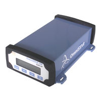
OmniSTAR 8200HP
Fugro OmniSTAR 8200HP Manuals
Manuals and User Guides for Fugro OmniSTAR 8200HP. We have
1
Fugro OmniSTAR 8200HP manual available for free PDF download: User Manual
Fugro OmniSTAR 8200HP User Manual (88 pages)
OmniSTAR
Brand:
Fugro
| Category:
GPS
| Size: 2 MB
Table of Contents
User Manual
1
Table of Contents
4
Table of Contents
9
Introduction
9
About this Manual
9
About Thi Manual
9
System Features
9
Receiver Features
10
Housing
10
Accessories
11
LIST of FIGURES Figure 1: 8200HP Back End
11
Table 1: 8200HP Interfaces
11
Figure 2: Z+ Antenna
12
Installation and Set up
13
Installation Considerations
13
Counter Electromagnetic Force (Cemf)
14
Figure 3: Zener Diode Connected
14
Cable Installation
15
Features and Information
16
Strobes
16
Receiver Status
16
Mounting the Receiver
16
Antenna Location
17
Power Supply Requirements
17
Operating Considerations
18
Number of Visible Satellites
18
Multipath
18
Figure 4: Multipath
18
Position Dilution of Precision (Pdop)
19
Satellite Elevations
19
Omnistar Corrections
19
Interference
19
Operation
20
Getting Started
20
Communicating with the Receiver
20
Starting the Receiver
20
The Receiver Home Screen
21
Figure 5: Home Screen When Omnistar HP Corrections Are Received
21
Table 2: Position Types
22
The 8200Hp Menu Structure
23
Table 3: Differential Information
23
Figure 6: Status Screen
24
Figure 7: Configuration Screen
24
Sub-Menu: Display Options
24
Top-Level: Configuration
24
Top-Level: Home
24
Top-Level: Status
24
Figure 10: Lock Display Screen
25
Figure 8: Contrast Screen
25
Figure 9: User Level Screen
25
Figure 11: Lock Display - Enter Password Screen
26
Figure 12: Language Screen
26
Figure 13: Units Screen
26
Figure 14: SNR Units Screen
27
Figure 15: Clear BB RAM Screen
28
Figure 16: Update Receiver Screen
28
Figure 17: Update Receiver - Enter Password Screen
28
Figure 18: GPS Lat/Long Screen
29
Figure 19: GPS Altitude Screen
29
Figure 20: GPS Speed and Heading Screen
29
Sub-Menu: GPS Status
29
Figure 21: GPS Channel Status Screen
30
Figure 22: GPS DOP Values Screen
30
Sub-Menu: DGPS Status
30
Figure 23: DGPS Sat Tracking Screen
31
Figure 24: Service ID Screen
31
Figure 25: DGPS Data Source Screen
31
Figure 26: Age of Dgps/Sync Screen
32
Figure 27: VBS Info Screen: User Code
32
Figure 28: VBS Info Screen: User Enabled
32
Figure 29: VBS Info Screen: Stop
33
Figure 30: VBS Info Screen: Received Data
33
Figure 31: VBS Info Screen: VBS Service Level
33
Figure 32: VBS Info Screen: VBS Version
33
Figure 33: VBS Info Screen: Figure of Merit
34
Figure 34: HP/XP Info Screen: User Code
34
Figure 35: HP/XP Info Screen: Initialisation
34
Figure 36: HP/XP Info Screen: Solution Convergence
34
Figure 37: HP/XP Info Screen: Stop
35
Figure 38: HP/XP Info Screen: Subscription Type
35
Figure 39: HP/XP Info Screen: Subscription Mode
35
Figure 40: HP/XP Info Screen: HP Version
36
Figure 41: XP/HP Info Screen: Srvc ID Screen 1
36
Figure 42: XP/HP Info Screen: Srvc ID Screen 2
36
Table 4: XP/HP Subscription Types
36
Figure 43: UTC Time and Day
37
Figure 44: UTC Date and GPS Week
37
Figure 45: Receiver Serial Number
37
Sub-Menu: Receiver Status
37
Figure 46: Receiver Firmware Version
38
Figure 47: Receiver Options: Fast Rate
38
Figure 48: Receiver Options: Base Station
38
Figure 49: Receiver Options: Everest Multipath Rejection
39
Figure 50: Receiver Options: Modem Control
39
Figure 51: Receiver Options: D&E Sub
39
Figure 52: Receiver Options: TNL Sub
39
Figure 53: Receiver Options: Carrier Phase
39
Figure 54: Receiver Options: VRS Processing
40
Figure 55: Receiver Options: Tilt Sensor
40
Figure 56: Position Error Caused by a Tilted, High-Mounted Receiver Antenna
40
Figure 57: Receiver Options: WAAS
41
Figure 58: Receiver Options: CMR Input
41
Figure 59: Receiver Options: Point/Line/Area
41
Figure 60: Receiver Options: CAN Bus
41
Figure 61: System Voltages
42
Figure 62: System Temperature
42
Figure 63: Incident Code
42
Figure 64: J1939 Address Claim Channel a
43
Figure 65: J1939 Address Claim Channel B
43
Figure 66: Channel a TPCAN Connections
43
Sub-Menu: CAN Status
43
Figure 67: Channel B TPCAN Connections
44
Figure 68: Restore GPS Defaults
44
Figure 69: GPS Mode
44
Sub-Menu: GPS Config
44
Figure 70: System Masks
45
Figure 71: PDOP Settings
45
Figure 72: Position Filter
46
Figure 73: Carrier Code Filter
46
Figure 74: Position Rate
46
Figure 75: Dynamic Mode
47
Figure 76: GPS Diagnostics
47
Figure 77: DGPS Source Select
47
Sub-Menu: DGPS Config
47
Figure 78: DGPS Backup Source Select
48
Figure 79: DGPS Correction Age
48
Figure 80: EZ Sat
49
Figure 81: Satellite Frequency
49
Figure 82: Satellite Baudrate
49
Figure 83: HP/XP Autoseed
50
Figure 84: HP/XP Init Mode
50
Figure 85: HP/XP Convergence Limit
51
Figure 86: Omnistar HP/XP Debug Information Screen
51
Figure 87: Port a I/O Configuration Settings
51
Sub-Menu: Port a Config
51
Table 5: 8200HP Input Protocols
52
Figure 88: Port-A Modem Control Options
53
Table 6: 8200HP Output Protocols
53
Figure 89: NMEA Messages 1
54
Figure 90: NMEA Messages 2
55
Figure 91: NMEA Messages 3
55
Figure 92: NMEA/TSIP Output Rates
55
Figure 93: 1Hz NMEA Message Output
56
Figure 94: NMEA Quality Configuration
56
Sub-Menu: Port B Config
56
Table 7: (D)GPS Quality Indicators
56
Figure 95: Port B I/O Configuration Settings
57
Figure 96: Port C out Screen
57
Sub-Menu: CAN a Config
57
Sub-Menu: Port C Config
57
Figure 97: CAN-Bus Baudrate Setting
58
Figure 98: CAN-Bus Address Setting
58
Figure 99: CAN-Bus Messages
58
Figure 100: CAN-Bus Message Rates
59
Figure 101: NMEA 2000 Messages 1
59
Figure 102: NMEA 2000 Messages 2
59
Figure 103: NMEA 2000 Message Rates
60
Figure 104: TPCAN Protos
60
Table 8: NMEA 2000 Default Message Rates
60
Figure 105: CAN-Bus Self-Configured Address
61
Technical Specifications
62
Appendix A
62
Performance
62
Environmental
62
Power Requirements
63
RF Input / LNA Power Output
63
Input / Output Data Interface
63
Input / Output Connectors
63
Physical Dimensions
63
Figure 106: Pin Layout (Receiver Connector)
64
Table 9: 8200HP Power/Data Port Pin-Out Descriptions (both Port a and B)
64
Appendix B
65
Nmea 0183 Message Options
65
Table 10: NMEA 0183 Messages Available for the 8200HP
65
Nmea 0183 Message Formats
66
GGA - GPS Fix Data
66
Table 11: Description of the GGA Message
66
GLL - Geographic Position - Latitude/Longitude
67
GRS - GPS Range Residuals
67
Table 12: Description of the GLL Message
67
Table 13: Description of the GRS Message
67
GSA - GPS DOP and Active Satellites
68
Table 14: Description of the GSA Message
68
GST - GPS Pseudorange Noise Statistics
69
Table 15: Description of the GST Message
69
GSV - GPS Satellites in View
70
Table 16: Description of the GSV Message
70
MSS - Beacon Receiver Signal Status
71
Ptnlsm
71
Proprietary (RTCM Special)
71
PTNLSM – Proprietary (RTCM Special)
71
Table 17: Description of the MSS Message
71
Table 18: Description of the PTNLSM Message
71
Ptnlev
72
Proprietary (Event Marker)
72
Proprietary (Receiver ID)
72
PTNLEV – Proprietary (Event Marker)
72
PTNLID – Proprietary (Receiver ID)
72
Table 19: Description of the PTNLEV Message
72
Table 20: Description of the PTNLID Message
72
Ptnldg
73
Proprietary (DGPS Receiver Status)
73
PTNLDG – Proprietary (DGPS Receiver Status)
73
Table 21: Description of the PTNLDG Message
73
PTNL,GGK - Time, Position, Position Type, DOP
74
Table 22: Description of the PTNL,GGK Message
74
RMC - Recommended Minimum Specific GPS Data
75
Table 23: Description of the RMC Message
75
VTG - Course over Ground and Ground Speed
76
Table 24: Description of the VTG Message
76
ZDA - Time and Date
77
Table 25: Description of the ZDA Message
77
Appendix C
78
Acronyms Used in this Manual
78
Appendix D
79
Updating the 8200Hp Firmware
79
Figure 107: Flashloader Main Screen
79
Figure 108: Firmware Image Selection Screen
80
Figure 109: Establishing Communication with the Receiver
80
Figure 110: Receiver Selection Screen
81
Figure 111: Uploading Firmware Screen
82
Figure 112: Erasing Program Space Screen
82
Figure 113: Programming New Firmware Screen
83
Figure 114: Flashing Completed Successfully
83
Appendix E
85
Omnistar Reference Stations
85
Receiver Service Procedure
86
Appendix F
86
Appendix G
87
Omnistar Receiver Problem Report Form
87
User Notes
88
Advertisement
Advertisement
Related Products
Fugro OmniSTAR 3200LR12
Fugro SeaSTAR 8200 HP
Fugro Categories
Receiver
GPS
Signal Processors
More Fugro Manuals
Login
Sign In
OR
Sign in with Facebook
Sign in with Google
Upload manual
Upload from disk
Upload from URL