GE Profile PP945 Technical Service Manual
30- and 36-in. cooktops
Hide thumbs
Also See for Profile PP945:
- Owner's manual (40 pages) ,
- Dimensions and installation information (2 pages) ,
- Installation instructions manual (17 pages)
Table of Contents
Advertisement
GE Consumer & Industrial
Technical Service Guide
January 2007
Profi le
30- and 36-in.
Cooktops
PP945
PP975
31-9149
GE Appliances
General Electric Company
Louisville, Kentucky 40225
GE
Profile
WARMING ZONE
ON/OFF
ON/OFF
ON/OFF
12 IN
9 IN
6 IN
ON/OFF
ON/OFF
CONTROL
LOCK
HOT SURFACE
GE
Profile
ON/OFF
ON/OFF
ON/OFF
ON/OFF
12 IN
9 IN
6 IN
H
S
C
OT
URFACE
ONTROL
L
OCK
Advertisement
Table of Contents
Troubleshooting

Related Manuals for GE Profile PP945


Summary of Contents for GE Profile PP945
- Page 1 GE Consumer & Industrial Technical Service Guide January 2007 Profi le 30- and 36-in. Cooktops PP945 Profile ON/OFF PP975 ON/OFF ON/OFF ON/OFF 12 IN 9 IN 6 IN URFACE ONTROL Profile WARMING ZONE ON/OFF ON/OFF ON/OFF 12 IN 9 IN...
- Page 2 If grounding wires, screws, straps, clips, nuts, or washers used to complete a path to ground are removed for service, they must be returned to their original position and properly fastened. GE Consumer & Industrial Technical Service Guide Copyright © 2007 All rights reserved.
-
Page 3: Table Of Contents
Table of Contents Component Locator Views ............................13 Component Quick Reference Troubleshooting ....................20 Control Features ................................8 Cooktop Components ..............................15 Cooktop Removal From Countertop ........................15 Daughter Relay Module (DRM) ............................16 Diagnostics and Service Information ........................20 Dimensions and Clearances ............................7 Electrical Requirements ..............................6 Element Hot Light Troubleshooting .........................22 Element Resistance Troubleshooting ........................21 Glass Top .....................................15... -
Page 4: Nomenclature
Nomenclature Model Number P P 9 7 5 B M 1 B B Brand Product Color B = Black P = Profi le S = Black Glass W/Stainless Trim W = White Confi guration P = Cooktop Engr. Revision Model Year Designator Feature Pack Designates Features - the higher Color Designator... -
Page 5: Introduction
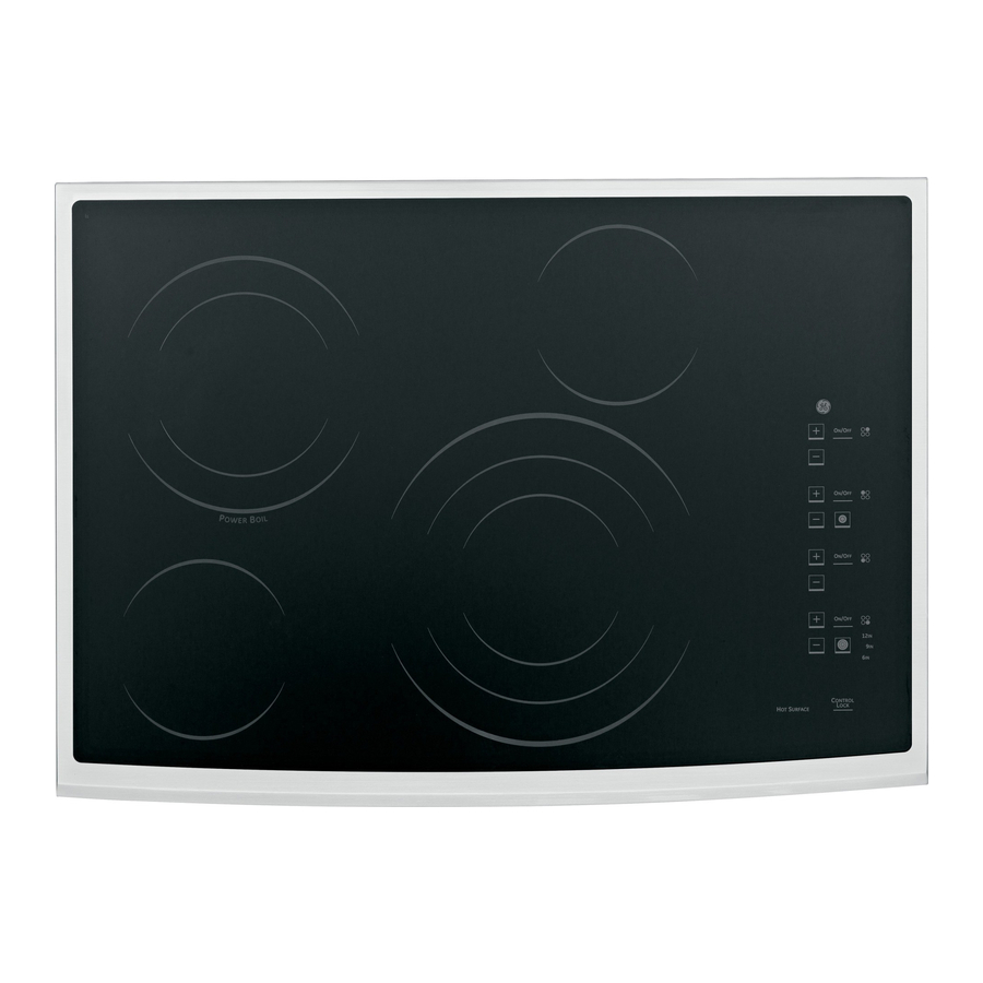
Introduction The new electronic cooktops make an eloquent statement of style, convenience, and kitchen planning fl exibility. The electronic touch controls are simple to understand and easy to operate–just read and touch. Model Number PP945 Profile ON/OFF ON/OFF ON/OFF ON/OFF... -
Page 6: Electrical Requirements
Installation WIRING Electrical Requirements Built-in power leads are UL approved for connection GROUNDING SPECIFICATIONS to larger gauge household wiring. The insulation of these leads is rated at temperatures much higher Ground Path Resistance 0.10 Ω Max. than the temperature rating of household wiring. Insulation Resistance 250K Ω... -
Page 7: Dimensions And Clearances
21-3/8″ (21-1/2″ SS) (29-7/8″ SS) 3-1/4″ Front Install junction box so 4-5/8″ Rear Cooktop that it can be reached at the conduit through the front of location the cabinet. 6-1/4″ Rear 33-3/4″ 18-7/8″ on Model PP945 & PP950 – 7 –... -
Page 8: Control Features
Control Features Features of your cooktop. ge.com Throughout this manual, features and appearance may vary from your model. Feature Index Explained on page (Features and appearances may vary.) Single Surface Element Dual Surface Element Tri-Ring Surface Element Warming Zone Surface Element... -
Page 9: Using The Surface Elements
Using the surface elements. Your new Profile Cooktop makes an eloquent statement of style, convenience, and kitchen planning flexibility. Whether you chose it for its purity of design, assiduous attention to detail, or for both of these reasons—you’ll find that your Profile cooktop’s superior blend of form and function will delight you for years to come. -
Page 10: Single Surface Element
Single Surface Element To turn on a single surface element: To turn off a single surface element, touch the ON/OFF pad again. Touch the ON/OFF pad, then touch the (+)/(-) pad. Use the (+)/(-) pad to choose the desired power setting. The control will beep each time a pad is touched. -
Page 11: Warming Zone Surface Element
Using the surface elements. Warming Zone Surface Element (on some models) To turn on the warming zone surface Use only cookware recommended for top-of-range cooking. element: The WARMING ZONE will keep hot, Touch the warming zone ON/OFF cooked food at serving temperature. pad, then touch the (+)/(-) pad. -
Page 12: Operation Overview
Operation Overview DIGITAL CONTROL SYSTEM The digital control system consists of 3 circuit boards: The touch board (permanently adhered to the ceramic glass panel) senses user input, including control lockout, displays user settings, contains HOT lights and key touch beeper. It is the “Main” board for the system. -
Page 13: Component Locator Views
Component Locator Views Front View (Model PP945) Glass Top With Permanently Attached Touch Board Burner Box Relay Power Supply Module Drop Box Relay Power Supply Module (RPSM) Top View - Glass Top Removed Single Surface Element Dual Surface Element Daughter Relay Module... - Page 14 Front View (Model 975PP) Glass Top With Permanently Attached Touch Board Burner Box Relay Power Supply Module Drop Box Relay Power Supply Module (RPSM) Top View - Glass Top Removed Tri-Ring Surface Element Warming Zone Surface Element Single Surface Element Dual Surface Element Dual Surface Element Daughter Relay Module...
-
Page 15: Cooktop Components
Push upward on the bottom of the burner box Slowly lift the front of the glass top (PP975), approximately 4 in. and rotate slightly left or or the right side of the glass top (PP945), right (to the best working advantage). Shim approximately 6 inches. -
Page 16: Daughter Relay Module (Drm)
Mark and disconnect wiring from the module. Compress the 4 tabs and lift the module from the recess in the burner box. Compression Tab Retainer Model PP975 Model PP945 – 16 –... -
Page 17: Relay Power Supply Module (Rpsm)
Note: The module is held in place by 5 retainers Relay Power Supply Module (RPSM) that lock the board in place using compression tabs. It may be helpful to remove the ink tube from an If the RPSM is damaged or defective, it can be inexpensive ballpoint pen and place the barrel of accessed by opening the drop box that is under the the pen over each retainer to compress the tab. -
Page 18: Heating Elements
2 springs are on the 2 posts. Post Single Element Dual Element Spring Dual Element Tri-Ring Element 6-in. Warmer On model PP945, the circular heating elements come in 3 sizes. Single Element Dual Element Tri-Ring Element (Continued next page) – 18 –... - Page 19 Mark the numbers on the bottom of the element next to the tabs. Remove the two ¼-in. hex-head screws and tabs. Install them on the new element in the same numbered position. Mark Number Mark Number – 19 –...
-
Page 20: Component Quick Reference Troubleshooting
Diagnostics and Service Information Component Quick Reference Troubleshooting Supply Voltage Wiring RPSM Touch Board Element DEAD UNIT: Turn off circuit breaker, wait 30 seconds, and turn circuit breaker on. Proceed to tests below. DISPLAY CHECK: Turn burner on Level 8. All segments should light. Set 4 burners to 1, 2, 5, and 8. Check for proper digit displays. -
Page 21: Element Resistance Troubleshooting
The resistance of certain elements and the continuity of certain element circuit wiring can be tested without removing the cooktop from its installation. This test will aid the service technician in determining if the RPSM or the DRM should be replaced. This test assumes the touch board functions properly. Model PP945 Component Ohms... -
Page 22: Element Hot Light Troubleshooting
Element Hot Light Troubleshooting Each element's hot light limiter switch and its wiring can be tested without removing the cooktop from its installation. This test will aid the service technician in determining if the element should be replaced. This test assumes the elements heat properly. -
Page 23: Schematics And Wiring Diagrams
Schematics and Wiring Diagrams Model PP945 - Element 240 VAC Schematic WARNING: Disconnect electrical power before servicing. Caution: Label all wires prior to disconnection. Wiring errors can cause improper and dangerous operation. Verify operation after servicing. (Continued next page) – 23 –... - Page 24 WIRING DIAGRAM MODEL PP945 – 24 –...
- Page 25 MODEL PP975 - ELEMENT 240 VAC SCHEMATIC WARNING: Disconnect electrical power before servicing. Caution: Label all wires prior to disconnection. Wiring errors can cause improper and dangerous operation. Verify operation after servicing. (Continued next page) – 25 –...
- Page 26 WIRING DIAGRAM MODEL PP975 – 26 –...
-
Page 27: Warranty
This warranty is extended to the original purchaser and any succeeding owner for products purchased for home use within the USA. If the product is located in an area where service by a GE Authorized Servicer is not available, you may be responsible for a trip charge or you may be required to bring the product to an Authorized GE Service location for service.
Need help?
Do you have a question about the Profile PP945 and is the answer not in the manual?
Questions and answers