IBM DCAS-32160 - Ultrastar 2.1 GB Hard Drive Specifications
Hard drive specifications
Hide thumbs
Also See for DCAS-32160 - Ultrastar 2.1 GB Hard Drive:
- Quick installation manual (2 pages)

Related Manuals for IBM DCAS-32160 - Ultrastar 2.1 GB Hard Drive


Summary of Contents for IBM DCAS-32160 - Ultrastar 2.1 GB Hard Drive
- Page 1 S73H-7993-03 OEM HARD DISK DRIVE SPECIFICATIONS for DCAS-34330 / DCAS-32160 SCSI-3 FAST-20 50/68/80-pin 3.5-Inch Hard Disk Drive ( 4330 / 2160 MB ) Revision (1.2)
- Page 3 S73H-7993-03 OEM HARD DISK DRIVE SPECIFICATIONS for DCAS-34330 / DCAS-32160 SCSI-3 FAST-20 50/68/80-pin 3.5-Inch Hard Disk Drive ( 4330 / 2160 MB ) Revision (1.2)
- Page 4 It is possible that this publication may contain reference to, or information about, IBM products (machines and programs), programming, or services that are not announced in your country. Such references or information must not be construed to mean that IBM intends to announce such IBM products, programming, or services in your country.
-
Page 5: Table Of Contents
..........Copyright IBM Corp. 1996... - Page 6 6.3.3 80-Pin Model ..........6.4 Environment .
- Page 7 7.6.5 Inquiry Data Format - EVPD = 1 - Page Code = 03 ..... . . 7.6.6 Inquiry Data Format - EVPD = 1 - Page Code = 80h .
- Page 8 7.30 START/STOP UNIT (1B) ......... 7.31 SYNCHRONIZE CACHE (35) .
- Page 9 10.4 Action codes ..........11.0 Additional Information .
- Page 10 12.2.3 ILI : Incorrect Length Indicator (Bit 5 of byte 2) ......12.2.4 Sense Key (Bit 3 - 0 of byte 2) .
- Page 11 ........Copyright IBM Corp. 1996...
- Page 12 Defect Descriptor - Block Format ........Defect Descriptor - Bytes From Index Format .
- Page 13 107. SEEK (0B) ..........108.
- Page 14 O E M Spec. of DCAS-34330/32160...
-
Page 15: General
32 x 1,024 bytes 64KB 64 x 1,024 bytes Mb/sq.in 1,000,000 bits per square inch Machine Level Control Predictive Failure Analysis (Trademark of IBM Corp.) S.M.A.R.T. Self-Monitoring Analysis and Reporting Technology Automatic Drive Maintenance SCAM SCSI Configured AutoMatically 1.4 General Caution... - Page 16 O E M Spec. of DCAS-34330/32160...
-
Page 17: Outline Of The Drive
5400rpm spindle rotation. Closed loop actuator servo Dedicated head landing zone Automatic actuator lock Informational Exceptions Control Page of SCSI-3 support as PFA or S.M.A.R.T. function Note: PFA which means Predictive Failure Analysis is Trademark of IBM Corporation. Copyright IBM Corp. 1996... - Page 18 O E M Spec. of DCAS-34330/32160...
-
Page 19: Part 1. Functional Specification
Part 1. Functional Specification Copyright IBM Corp. 1996... - Page 20 O E M Spec. of DCAS-34330/32160...
-
Page 21: Fixed Disk Subsystem Description
The actuator assembly is balanced to allow vertical or horizontal mounting without adjustment. When the drive is powered off, the actuator automatically moves the head to a dedicated landing zone outside of the data area, where the actuator is locked. Copyright IBM Corp. 1996... - Page 22 O E M Spec. of DCAS-34330/32160...
-
Page 23: Drive Characteristics
3 x 128Kbyte 1 x 448Kbyte (without tagged queuing) Rotational speed [ R P M ] 5400 Recording density [ Kbpi] 114.4(Ave) / 134.6(Max) Track density [ TPI] 8600 Areal density [ Mb/sq.in.] 981(Ave) / 1158(Max) Data zone Copyright IBM Corp. 1996... -
Page 24: Cylinder Allocation
3.3 Cylinder Allocation Phys. Cyl. Sectors/Trk System Area Data Zone 0 0-857 Data Zone 1 858-2684 Data Zone 2 2685-3362 Data Zone 3 3363-4287 Data Zone 4 4288-5379 Data Zone 5 5380-6242 Data Zone 6 6243-6920 Data Zone 7 6921-8209 System Area Mode page 03 (Format Device Parameters) and 0C (Zone Parameters) provide methods to determin medium format and zone parameters. -
Page 25: Command Overhead
3.4.1 Command overhead Command overhead is defined as the time required: from last byte of command phase to the first byte of data phase excluding Physical seek time Latency time Initiator delay with reconnections Command Case (Drive is in quiescence state) Time Cache Not Hit <0.70msec... -
Page 26: Full Stroke Seek Time
3.4.2.2 Full Stroke Seek Figure 5. Full Stroke Seek Time Function Typical Max. Read [ msec] Write [ msec] 15.5 Full stroke seek is measured as the average of 1000 full stroke seeks with a random head switch from both directions (inward and outward). -
Page 27: Drive Ready Time
3.4.3 Drive Ready Time Figure 9. Drive Ready Time Condition Typical Max. Power On to Ready (DCAS-34330) 15 [ sec] 20 [ sec] Power On to Ready (DCAS-32160) 12 [ sec] 18 [ sec] Ready The condition in which the drive is able to perform a media access command (eg. read, write) immediately. -
Page 28: Buffering Operation (Lookahead/Write Cache)
3.4.5 Buffering Operation (Lookahead/Write Cache) At shipment, the total 448K bytes of the buffer is divided into 7 segmented blocks. The segment size can be changed by Mode Page 8. See 7.12.7, “Page 8 (Caching Parameters)” on page 113 for details. O E M Spec. -
Page 29: Throughput
3.4.6 Throughput 3.4.6.1 Simple Sequential Access Figure 11. Simple Sequential Access Performance Operation Typical Sequential Read/Write Zone 0 2.26 [ sec] Zone 0 2.37 [ sec] Zone 7 3.56 [ sec] Zone 7 3.73 [ sec] The above table gives the time required to read/write for a total of 8000x consecutive blocks (16,777,216 bytes) accessed by 128 read/write commands. -
Page 30: Operating Mode Definition
3.4.7 Operating Mode Definition Operating Mode Description Spin-Up Start up time period from spindle stop or power down. Seek Seek operation mode Write Write operation mode Read Read operation mode Idle Spindle motor and servo system are working normally. Commands can be received and processed immediately. -
Page 31: Data Integrity
“Write fault” is detected. 4.2 Error Recovery Errors occurring with the drive are handled by the error recovery procedure. Errors that are uncorrectable after application of the error recovery procedures are reported to the host system as non-recoverable errors. Copyright IBM Corp. 1996... - Page 32 O E M Spec. of DCAS-34330/32160...
-
Page 33: Physical Format
L B A 3 L B A 2 L B A 1 L B A S p a r e S p a r e Calculation from LBA to physical is done automatically by internal table. Copyright IBM Corp. 1996... - Page 34 O E M Spec. of DCAS-34330/32160...
-
Page 35: Specification
-DB(P) Ground Ground Ground Ground Ground Ground Open T R M Power Ground Ground Ground Ground Ground -ATN Ground Ground Ground -BSY Ground -ACK Ground -RST Ground -MSG Ground -SEL Ground -C/D Ground -REQ Ground -I/O Copyright IBM Corp. 1996... -
Page 36: Table Of Signals
6.1.1.3 SCSI Signal Connector (68-pin) The pin assignments of interface signals conforms to ANSI SCSI-3 X3T10/855D as follows. Figure 16. Table of Signals Connector Signal Name Connector Signal Name Contact Contact Number Number Ground -DB(12) Ground -DB(13) Ground -DB(14) Ground -DB(15) Ground -DB(P1) -
Page 37: Table Of Signals
6.1.1.4 SCSI Signal Connector (80-pin) The pin assignments of interface signals conform to SFF-8046 as follows. Figure 17. Table of Signals Connector Signal Name Connector Signal Name Contact Contact Number Number 12 Volt Charge 12V Ground 12 Volt 12V Ground 12 Volt 12V Ground 12 Volt... -
Page 38: Scsi Cable
6.1.2 SCSI Cable The drives comply with ANSI X3T10/1071D. The maximum cumulative signal path length between terminators shall be 3.0 meters when using up to 4 maximum capacitance (25pF) devices. The maximum cumulative signal path length between terminators shall be 1.5 meters when using from 5 to 8 maximum capacitance devices. -
Page 39: Scsi Bus Electrical Characteristics
6.1.5 SCSI Bus Electrical Characteristics The interface logic signals has the following electrical specifications. Details should be referred to ANSI X3T10/1071D. I n p u t s I n p u t H i g h V o l t a g e 1 . - Page 40 D A S 3 D A S 2 S C S I I D E n a b l e S C S I T e r m i n a t o r D A S 1 + 5 V D A S 0 P i n # : ( R e s e r v e d )
-
Page 41: Option Jumper Block
L o g i c C a r d P i n # : D i s k E n c l o s u r e Figure 19. Jumper Pins Note : The pin alocation is not compatible with previous IBM HDDs such as DPES-xxxxx, DALS-xxxxx. Specification... -
Page 42: Option Jumper Block Assignment
N o t e : ( x ) s h o w s P o s i t i o n N u m b e r G R O U N D ( 1 ) D A S 3 ( 2 ) D A S 2 ( 3 ) -
Page 43: Jumper Signal Description
6.2.1 Jumper Signal Description Throughout this paragraph O N means a shunt jumper is installed and O F F means that no shunt jumper is installed. 6.2.1.1 Device address select lines. (-DAS0, -DAS1, -DAS2, -DAS3) These four lines defines DCAS-3xxxx device ID on the SCSI BUS. -DAS0 is the least significant bit and -DAS3 is the most significant bit. - Page 44 6.2.1.4 Disable Unit Attention. (Position 7) Grounding this pin (jumper on) enables control of UAI (Unit Attention Inhibit) bit in Mode Page 0. 6.2.1.5 Enable TI-SDTR (50-pin) / Enable TI-SDTR/WDTR (68,80-pin) Grounding this pin (jumper on) enables the following. Target Initiated Wide Data Transfer Request Negotiation (68,80-pin) Target Initiated Synchronous Data Transfer Request Negotiation (50,68,80-pin) O E M Spec.
-
Page 45: Disable Auto Spin Up ,Auto Start Delay & Delay Start
6.2.1.6 Auto Start Delay & Delay Start 6/12 (Position 9 & 10) The Auto Start Delay and Delay Start 6/12 pins control when and how the drive can spin up, with the combination of Disable Auto Spin Up (Position 5). When both Auto Spin up and Auto Start Delayis are enabled, the drive start will be delayed by a period of time multiplied by its own SCSI address. -
Page 46: Shipping Default
6.2.2 Shipping Default SCSI ID is set to #6 as shipping default. SCSI terminator is enabled as shipping default. No jumper is set as shipping default on 80-pin model. P o s i t i o n # : S h u n t j u m p e r s a r e i n s t a l l e d a t p o s i t i o n 2 , 3 a n d 6 a s s h i p p i n g d e f a u l t o f 5 0 p i n / 6 8 p i n m o d e l . -
Page 47: Led Circuit
6.3 LED Circuit Jumper pin #1 and #2 are used to drive an external LED. Instead of the the jumper pins, the following pins can be used to drive LED. 68-Pin Model : Auxiliary Connector Pin #8 and #11. 80-Pin Model : SCA-2 Connector Pin #77 as shown in 6.3.3, “80-Pin Model” on page 35. The schematics of LED circuit on each model are as follows. -
Page 48: 68-Pin Model
6.3.2 68-Pin Model D C A S 3 4 3 3 0 / D C A S 3 2 1 6 0 6 8 P i n M o d e l E x a m p l e o f U s a g e a t S y s t e m S i d e A u x i l i a r y C o n n e c t o r P i n # 1 1... -
Page 49: 80-Pin Model
6.3.3 80-Pin Model D C A S 3 4 3 3 0 / D C A S 3 2 1 6 0 8 0 P i n ( S C A 2 ) M o d e l : E x a m p l e o f U s a g e a t S y s t e m S i d e + 5 V + 5 V... -
Page 50: Environment
6.4 Environment Figure 28. Environmental Condition Operating Conditions Temperature 5 to 55[ ˚ C] (See note) Relative Humidity 8 to 90 [ % R H ] non-condensing Maximum Wet Bulb Temperature 29.4[ ˚ C] non-condensing Maximum Temperature Gradient 15[ ˚ C / Hour] Altitude 300 to 3048 [ m] Non-Operating Conditions... -
Page 51: Dc Power Requirements
6.5 DC Power Requirements Connection to the product should be made in isolated secondary circuits (SELV). The following voltage specification is applied at the power connector of the drive. No special power on/off sequencing is required. Figure 29. Input Voltage During run and spin up Absolute max voltage + 5 Volts Supply... -
Page 52: Start Up Current
Figure 32. Power Supply Generated Ripple at Drive Power Connector Maximum Notes + 5 V DC 100 [ mV pp] 0-10 [ MHz] + 1 2 V DC 150 [ mV pp] 0-10 [ MHz] During drive start up and seeking, 12 volt ripple is generated by the drive (referred to as dynamic loading). If several files have their power daisy chained together then the power supply ripple plus other drive's dynamic loading must remain within the regulation tolerance of + 1 0 / - 8 % . -
Page 53: Reliability
6.6 Reliability 6.6.1 Contact Start Stop (CSS) The drive is designed to withstand a minimum of 40,000 contact start/stop cycles under 40˚ C environment and a minimum of 10,000 contact start/stop cycles under extreme temperature or humidity environment. 6.6.2 Data Reliability Probability of not recovering data .. -
Page 54: Automatic Drive Maintenance (Adm)
The details are described in 7.12.10, “Page 1C (Informational Exceptions Control)” on page 119. 6.6.6 Automatic Drive Maintenance (ADM) A D M function is equipped to maintain the reliability even in continuous usage beyond one week. A D M function is to perform a CSS automatically after detection of idling time for 1 minute at intervals of 1 week. -
Page 55: Mechanical Specifications
6.7 Mechanical Specifications 6.7.1 Outline 6.7.1.1 50-pin Model Figure 34. Outline of 50-pin Model Specification... -
Page 56: Outline Of 68-Pin Model
6.7.1.2 68-pin Model Figure 35. Outline of 68-pin Model O E M Spec. of DCAS-34330/32160... -
Page 57: Outline Of 80-Pin Model
6.7.1.3 80-pin Model Figure 36. Outline of 80-pin Model Specification... -
Page 58: Mechanical Dimensions
6.7.2 Mechanical Dimensions The following chart describes the dimensions and the weight. Figure 37. Physical Dimension Height [ mm] 25.4 ± 0.4 Width [ mm] 101.6 ± 0.4 Length [ mm] 146.0 ± 0.6 Weight [ gram] 610 Max. Figure 38. Mechanical Dimension O E M Spec. -
Page 59: Interface Connector
6.7.3 Interface Connector 6.7.3.1 50-pin Model Figure 39. Interface Connector (50-pin Model) Specification... -
Page 60: Interface Connector (68-Pin Model)
6.7.3.2 68-pin Model Figure 40. Interface Connector (68-pin Model) O E M Spec. of DCAS-34330/32160... -
Page 61: Interface Connector (80-Pin Model)
6.7.3.3 80-pin Model Figure 41. Interface Connector (80-pin Model) Specification... -
Page 62: Mounting Positions And Tappings
6.7.4 Mounting Positions and Tappings Figure 42. Mounting Positions and Tappings O E M Spec. of DCAS-34330/32160... -
Page 63: Shipping Zone And Lock
6.7.4.1 Drive Mounting The drive will operate in all axes (6 directions). Performance and error rate will stay within specification limits if the drive is operated in the other orientations from which it was formatted. The recommended mounting screw torque is 0.6 - 1.0 [ N m ] (6 - 10 [ Kgf.cm]). The recommended mounting screw depth is 6 [ mm] Max for bottom and 3.5 [ mm] Max for horizontal mounting. -
Page 64: Vibration And Shock
6.8 Vibration and Shock All vibration and shock measurements in this section are made with the drive that has no mounting attach- ments for the systems. The input power for the measurements is applied to the normal drive mounting points. 6.8.1 Operating Vibration 6.8.1.1 Random Vibration The drive is designed to operate without unrecoverable errors while being subjected to the following... -
Page 65: Operating Shock
Overall RMS (Root Mean Square) level of vibration is 1.04G (RMS). 6.8.2.2 Swept Sine Vibration - 2 G (Zero to peak), 5 to 500 to 5 Hz sine wave - 0.5 oct/min sweep rate - 3 minutes dwell at two major resonances 6.8.3 Operating Shock The drive meets the following criteria. -
Page 66: Acoustics
6.9 Acoustics The following shows the acoustic levels. 6.9.1 Sound Power Levels The upper limit criteria of the A-weighted sound power levels are given in Bel relative to one pico watt and are shown in the following table. The measurment method is in accodance with ISO7779. Figure 46. -
Page 67: Sound Pressure (Reference)
3.19 2.74 2.74 2.49 2.33 2.22 2.13 2.07 2.01 1.97 1.93 1.90 1.87 The calculated left hand side of the criterion equation above is rounded to the nearest 0.05 bel. The indi- vidual terms may be rounded to the nearest 0.01 bel before calculation. 6.9.3 Sound Pressure (Reference) 6.9.3.1 Unit Sound Pressure Level Measurment The hard disk drives are measured in a semi-anechoic chamber, with background noise = <... -
Page 68: Identification Labels
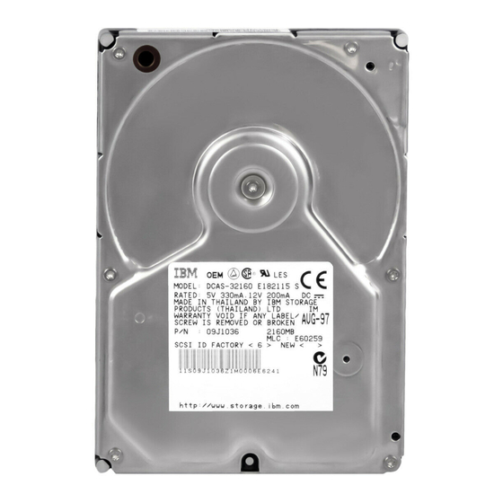
6.10 Identification Labels The following labels are attached to the drive. 1. A label placed on the top of the HDA contains the statement “Made by IBM” or equivalent, Part number, and MLC number. 2. A bar code label placed on the drive is based on user requests. The location is to be designated in the drawing. -
Page 69: Safety
6.12 Safety The following shows the safety standards for different countries. 6.12.1 Underwriters Lab (UL) Approval DCAS-3xxxx comply with UL 1950. 6.12.2 Canadian Standards Authority (CSA) Approval | DCAS-3xxxx comply with CSA C22.2 No.0M91, and CSA C22.2 No.950-93. 6.12.3 IEC Compliance DCAS-3xxxx comply with IEC 380, IEC 435 and IEC 950. - Page 70 O E M Spec. of DCAS-34330/32160...
-
Page 71: Part 2. Scsi Interface Specification
Part 2. SCSI Interface Specification Copyright IBM Corp. 1996... - Page 72 O E M Spec. of DCAS-34330/32160...
-
Page 73: Scsi Command Set
RESERVE REZERO UNIT SEEK SEEK EXTENDED SEND DIAGNOSTICS START/STOP UNIT SYNCHRONIZE CACHE TEST UNIT READY VERIFY WRITE WRITE AND VERIFY WRITE BUFFER WRITE EXTENDED WRITE LONG WRITE SAME Figure 48. SCSI Commands Supported. (In Alphabetical order) Copyright IBM Corp. 1996... -
Page 74: Flag And Link Bits
SCSI-1 SCSI-2 CODE COMMAND TEST UNIT READY REZERO UNIT REQUEST SENSE FORMAT UNIT REASSIGN BLOCKS READ WRITE SEEK INQUIRY MODE SELECT (6) RESERVE RELEASE MODE SENSE (6) START/STOP UNIT RECEIVE DIAGNOSTICS SEND DIAGNOSTICS READ CAPACITY READ EXTENDED WRITE EXTENDED SEEK EXTENDED WRITE AND VERIFY VERIFY PRE-FETCH... -
Page 75: Abbreviations
Upon unsuccessful completion of the command, the file will return CHECK CONDITION status or RESERVATION CONFLICT status and then send the C O M M A N D COMPLETE message. No further commands in the chain are executed. 7.2 Abbreviations These abbreviations are used throughout the following sections: LUN. -
Page 76: F O R M A T Unit (04)
7.4 FORMAT UNIT (04) Byte Command Code = 04h FmtData CmpList Defect List Format VU = 0 (MSB) Interleave Factor (LSB) VU = 0 Reserved = 0 FLAG LINK Figure 50. F O R M A T UNIT (04) The F O R M A T command performs a physical formatting of the file media. This includes handling of defec- tive sectors, and the overwriting of all data areas with a constant data pattern. -
Page 77: Format Of Defect List Header
Byte Reserved = 0 DPRY DCRT STPF IP = 0 DSP = 0 Immed (MSB) Defect List Length (LSB) Figure 51. Format of Defect List Header. Format of the defect list header sent during the data out phase when FmtData set to one. The Target has a limited implementation of the Format Option bits located in Bits 2 through 7 of Byte 1 of the Defect List Header (See Figure 51). -
Page 78: Defect Descriptor
Immed (Immediate) bit set to zero requests that status be returned at the end of the format operation. An immediate bit set to one requests that status be returned immediately. Good Status is returned fol- lowing the CDB validation and transfer of data in the Data Out phase. If the immediate format opera- tion terminates in error, Deferred Error Sense data is generated. -
Page 79: Defect Descriptor - Bytes From Index Format
Byte (MSB) Cylinder Number of Defect (LSB) Head Number of Defect (MSB) Defect Bytes from Index (LSB) 8n - Defect Descriptor n 8n + 7 Figure 53. Defect Descriptor - Bytes From Index Format. Format of the defect list sent during the data out phase when FmtData set to one. -
Page 80: Inquiry (12)
7.5 INQUIRY (12) Byte Command Code = 12h Reserved = 0 EVPD Page Code Reserved = 0 Allocation Length VU = 0 Reserved = 0 FLAG LINK Figure 55. INQUIRY (12) The INQUIRY command requests the parameters of the target to be sent to the initiator. An EVPD bit of one specifies that the file shall return the vital product data page identified by the Page Code field in the CDB. -
Page 81: Inquiry Data
7.6 Inquiry data Two different formats for the INQUIRY data are defined. The first format is returned when an invalid L U N is specified by the initiator. The second format is returned when a valid L U N is specified by the initiator. Each of these formats is described in the following sections. -
Page 82: Inquiry Data Format (When Invalid Lun Is Specified)
ANSI = 2 RSVD = 0 RDF = 2 Additional Length = 8F Reserved = 0 REL_A Wb_32 Wb_16 Sync Link TTD CmdQu SftRe 8 15 Vendor ID = 'IBM (ASCII) 16 31 Product ID (ASCII) 32 35 Product Revision Level (ASCII) Figure 56. -
Page 83: Product Id Vs. Formatted Capacity
SftRe is set to zero to indicate that the target supports Hard Reset only. Vendor ID is 'IBM' padded with ASCII blanks. Product ID is specified in ASCII character. Product ID... -
Page 84: Inquiry Data Format - Evpd
RSVD = 0 RDF = 2 Additional Length = 143 (8Fh) Reserved = 0 REL_A Wb_32 Wb_16 Sync Link TTD CmdQu SftRe 8 15 Vendor ID = 'IBM (ASCII) 16 31 Product ID (ASCII) 32 35 Product Revision Level (ASCII) - Page 85 CmdQu is set to one to indicate that the file supports command queuing SftRe is set to zero to indicate that the target supports Hard Reset only. Vendor ID is 'IBM' padded with ASCII blanks. Product ID is specified in ASCII character.
-
Page 86: Inquiry Data Format - Evpd = 1 - Page Code = 00
7.6.3 Inquiry Data Format - EVPD = 1 - Page Code = 00 BYTE Qualifier = 0 Peripheral Dev Type = 0 Page Code = 00h Reserved = 0 Page Length = 04h First Supported Page Code = 01h Second Supported Page Code = 03h Third Supported Page Code = 80h Fourth Supported Page Code = 82h Figure 59. -
Page 87: Inquiry Data Format - Evpd = 1 - Page Code = 01
7.6.4 Inquiry Data Format - EVPD = 1 - Page Code = 01 BYTE Qualifier = 0 Peripheral Dev Type = 0 Page Code = 01h Reserved = 0 Page Length = 47 (2Fh) ASCII Length = 24 (18h) 5 16 Reserved 18 27 Reserved... -
Page 88: Inquiry Data Format - Evpd = 1 - Page Code = 03
7.6.5 Inquiry Data Format - EVPD = 1 - Page Code = 03 BYTE Qualifier = 0 Peripheral Dev Type = 0 Page Code = 03h Reserved = 0 Page Length = 36 (24h) Reserved = ' ' (ASCII) 8 39 Reserved Figure 61. -
Page 89: Inquiry Data Format - Evpd = 1 - Page Code = 80H
7.6.6 Inquiry Data Format - EVPD = 1 - Page Code = 80h BYTE Qualifier = 0 Peripheral Dev Type = 0 Page Code = 80h Reserved = 0 Page Length = 16 (10h) 4 19 Serial Number (ASCII) Figure 62. INQUIRY DATA - EVPD = 1 (Page Code = 80h) Qualifier is set to zero to indicate that the L U N specified in the Command Block is currently supported. -
Page 90: Inquiry Data Format - Evpd = 1 - Page Code = 82H
ASCII Length = 28 (1Ch) Product Type (ASCII) 10 15 Model Number (ASCII) 17 24 Serial Number (ASCII) 26 31 Vendor ID 'IBM' (ASCII) 33 36 Product Type (EBCDIC) 38 43 Model Number (EBCDIC) Reserved = 0 45 52 Serial Number... - Page 91 Serial Number (ASCII) gives the file serial number. The field is left aligned and unused bytes are filled with 20h. Vendor ID (ASCII) gives the vendor as IBM. The field is left aligned and unused bytes are filled with 20h.
-
Page 92: Log Select (4C)
7.7 LOG SELECT (4C) Byte Command Code = 4Ch Reserved = 0 Reserved = 0 Reserved = 0 (MSB) Parameter List Length = 0 (LSB) Reserved = 0 FLAG LINK Figure 64. L O G SELECT (4C) The LOG SELECT command provides a means for the initiator to clear statistical information maintained by the drive and reported via the Log Sense command. -
Page 93: Log Sense (4D)
7.8 LOG SENSE (4D) Byte Command Code = 4Dh Reserved = 0 PPC = 0 Page Code Reserved = 0 (MSB) Parameter Pointer = 0 (LSB) (MSB) Allocation Length (LSB) Reserved = 0 FLAG LINK Figure 65. L O G SENSE (4D) The LOG SENSE command allows the initiator to retrieve the statistical data about the drive. -
Page 94: Log
7.8.1 Log Page parameters Each log page begins with a four-byte page header followed by zero or more variable-length log parameters. Page Header Page Code field identifies which log page is being transferred. The Page Length field specifies the length in bytes of the following log parameters. Log Parameters Each log parameter begins with a four-bytes parameter header followed by one or more bytes of parameter value data. -
Page 95: Log Sense
7.8.2 Log Sense Page 0 Byte Reserved Page code = 0 Reserved Page Length = 0006h (Number of Pages Supported) First supported page 0h Second supported page 2h Third supported page 3h Fourth supported page 5h Fifth supported page 6h Sixth supported page 3Ah Page 0 indicates the supported log sense pages. -
Page 96: Log Sense
7.8.3 Log Sense Page 2 This page contains counters for write errors Byte Reserved Page code = 02h Reserved 2 - 3 PageLength = 38h 4 - 5 Parameter Code = 00h T M C = 0 LBIN Parameter Length = 04h 8 - 11 Errors recovered without delay = 0 12 - 13... - Page 97 Byte 44 - 45 Parameter Code = 05h T M C = 0 LBIN Parameter Length = 04h 48 - 51 Total bytes written 52 - 53 Parameter Code = 06h T M C = 0 LBIN Parameter Length = 04h 56 - 59 Count of LBA's with hard error SCSI C O M M A N D SET...
-
Page 98: Log Sense
7.8.4 Log Sense Page 3 This page contains counters for read errors Byte Reserved Page code = 03h Reserved 2 - 3 PageLength = 38h 4 - 5 Parameter Code = 00h T M C = 0 LBIN Parameter Length = 04h 8 - 11 Errors recovered without delay = 0 12 - 13... - Page 99 Byte 44 - 45 Parameter Code = 05h T M C = 0 LBIN Parameter Length = 04h 48 - 51 Total bytes read 52 - 53 Parameter Code = 06h T M C = 0 LBIN Parameter Length = 04h 56 - 59 Count of LBA's with hard error The drive will attempt to read data after a seek before the head has fully settled on track.
-
Page 100: Log Sense
7.8.5 Log Sense Page 5 This page contains counters for verify errors Byte Reserved Page code = 05h Reserved 2 - 3 PageLength = 38h 4 - 5 Parameter Code = 00h T M C = 0 LBIN Parameter Length = 04h 8 - 11 Errors recovered without delay = 0 12 - 13... - Page 101 Byte 44 - 45 Parameter Code = 05h T M C = 0 LBIN Parameter Length = 04h 48 - 51 Total bytes written 52 - 53 Parameter Code = 06h T M C = 0 LBIN Parameter Length = 04h 56 - 59 Count of LBA's with hard error The drive will attempt to read data after a seek before the head has fully settled on track.
-
Page 102: Log Sense
7.8.6 Log Sense Page 6 This page contains counters for non-medium errors. This includes seek errors and other hardware type fail- ures. Byte Reserved Page code = 06h Reserved 2 - 3 PageLength = 08h 4 - 5 Parameter Code = 00h T M C = 0 LBIN Parameter Length = 04h... -
Page 103: Log Sense Page 3A
7.8.7 Log Sense Page 3A Log Sense Page 3A is reserved and this page of the specification is intentionally left blank. SCSI C O M M A N D SET... -
Page 104: Mode Sense (1A)
7.9 MODE SENSE (1A) Byte Command Code = 1Ah Reserved = 0 Page Code Reserved = 0 Allocation Length VU = 0 Reserved = 0 FLAG LINK Figure 66. M O D E SENSE (1A) The M O D E SENSE (1A) command provides a means for the file to report various device parameters to the initiator. -
Page 105: Mode Parameter List
Report saved value. The file returns the saved value for the page code specified. Saved values are one of following : the values saved as a result of M O D E SELECT command identical to the default values zero when the parameters are not supported The Page Length byte value of each page returned by the file indicates up to which fields are sup- ported on that page. -
Page 106: Mode Parameter Header
BYTE 0 (MSB) Mode Data Length BYTE 1 (LSB) BYTE 2 Medium Type = 0 BYTE 3 Reserved = 0 BYTE 4 Reserved = 0 BYTE 5 Reserved = 0 BYTE 6 (MSB) Block Descriptor Length (= 0 or 8) BYTE 7 (LSB) Figure 69. -
Page 107: M O D E Parameter Page Format
Number of Blocks When used with the M O D E SELECT command, the Number of Blocks field must be; Zero to indicate not to change available blocks 0 x F F F F F F to indicate all available blocks The exact number of blocks in the data area of the file, which can be obtained with the M O D E SENSE The number of blocks less than exact one, in order to CLIP the number of blocks... -
Page 108: Mode Sense (5A)
7.10 MODE SENSE (5A) Byte Command Code = 5Ah Reserved = 0 Page Code Reserved = 0 Reserved = 0 Reserved = 0 Reserved = 0 (MSB) Allocation Length (LSB) VU = 0 Reserved = 0 FLAG LINK Figure 72. M O D E SENSE (5A) The M O D E SENSE (5A) command provides a means for the file to report various device parameters to the initiator. -
Page 109: M O D E Select (15)
7.11 MODE SELECT (15) Byte Command Code = 15h PF = 1 Reserved = 0 Reserved = 0 Parameter List Length VU = 0 Reserved = 0 FLAG LINK Figure 73. M O D E SELECT (15) The M O D E SELECT (15) command provides a means for the initiator to specify L U N or device parame- ters to the Target. - Page 110 CHECK CONDITION status with sense key of ILLEGAL REQUEST. See 7.9, “MODE SENSE (1A)” on page 90. Note: If an initiator sends a M O D E SELECT command that changes any parameters that apply to other initiators, the file shall generate an unit attention condition for all initiators except the one that issued the M O D E SELECT command.
-
Page 111: Mode Select Data
7.12 Mode select data The file supports the following mode page code: Page Description Vendor Unique Parameters Read-Write Error Recovery Parameters Disconnect/Reconnect Control Parameters Format Device Parameters Rigid Disk Geometry Parameters Verify Error Recovery Parameters Caching Parameters Control Mode Page Notch Parameters Informational Exceptions Control Power Control Parameters... -
Page 112: Vendor Unique Parameters)
7.12.1 Page 0 (Vendor Unique Parameters) BYTE 0 RSVD=0 Page Code = 00h BYTE 1 Page Length = 0Eh BYTE 2 QPE Ignore UAI SCAM level DADM BYTE 3 RSVD=0 RSVD=0 CMDAC Ignore RSVD = 0 BYTE 4 RSVD = 0 BYTE 5 RSVD=0 TCC FRDD DPSDP RSVD=0 CAEN Ignore... - Page 113 FRDD DPSDP CAEN | IGRA LED Mode 0000b Command Aging Limit QPE Read Threshold QPE Write Threshold DRRT QPE (Qualify Post Error) bit allows the Initiator to inhibit the reporting of recovered data errors which are recovered under Data Recovery Procedure (DRP) step. A QPE bit of zero causes the Target to report all recovered data errors.
- Page 114 TCC (Thermal Compensation Control) bit is not used. It is allowed to be modified by the initiator for host system device driver compatibility. DSN (Disable Target Initiated Synchronous Negotiation) bit is not used and ignored internally. FRDD (Format/Reassign Degrade Disable) bit is not used and ignored internally. DPSDP (Data Phase Save Data Pointer) bit is not used and ignored internally.
-
Page 115: Read/Write Error Recovery Parameters)
7.12.2 Page 1 (Read/Write Error Recovery Parameters) BYTE 0 RSVD=0 Page Code = 01h BYTE 1 Page Length = 0Ah BYTE 2 AWRE ARRE EER=0 BYTE 3 Read Retry Count BYTE 4 Correction Span BYTE 5 Head Offset Count (Not used) BYTE 6 Data Strobe Offset Count (Not used) BYTE 7... - Page 116 A AWRE bit is set to one to indicate that the file shall perform automatic reallocation of defective data blocks during write operations. ARRE, an Automatic read reallocation enabled bit is set to zero to indicate that the file shall not perform automatic reallocation of defective data blocks during read operations.
- Page 117 The following summarizes valid modes of operation. If an illegal mode is set the mode select command will complete successfully but the action of the file when an error occurs is undefined. PER DTE DCR TB DESCRIPTION Retries and Error Correction are attempted. Recovered and/or corrected data (if any) is transferred with no CHECK CONDITION status at the end of the transfer.
- Page 118 The highest level error is reported at the end of transfer. Retries and error cor- rection are attempted. Recovered and/or corrected data (if any) is transferred with CHECK CONDITION status and RECOVERED E R R O R Sense Key set at the end of the transfer.
- Page 119 The highest level error is reported at the end of transfer. Retries and error cor- rection are attempted. Recovered and/or corrected data (if any) is transferred with CHECK CONDITION status and RECOVERED E R R O R Sense Key set at the end of the transfer.
-
Page 120: Disconnect/Reconnect Parameters)
7.12.3 Page 2 (Disconnect/Reconnect Parameters) BYTE 0 RSVD=0 Page Code = 02h BYTE 1 Page Length = 0Eh BYTE 2 Read Buffer Full Ratio BYTE 3 Write Buffer Empty Ratio BYTE Reserved = 0 Figure 77. Page 2 Changeable Parameter Default Value Read Buffer Full Ratio Write Buffer Empty Ratio... - Page 121 7.12.3.2 Reconnection to a disconnected write command For a write command, the Write Buffer Ratio is significant only if the total data transfer length is greater than the size of the file data buffer. The fraction determines how empty the file data buffer should be before reconnecting to begin filling the buffer again.
-
Page 122: Format Device Parameters)
7.12.4 Page 3 (Format Device Parameters) BYTE 0 PS = 0 RSVD=0 Page Code = 03h BYTE 1 Page Length = 16h BYTE 2 (MSB) Tracks per Zone = 5FF4h (DCAS32160/W) C04Eh (DCAS34330/W) BYTE 3 (LSB) BYTE 4 (MSB) Alternate Sectors per Zone = 0 BYTE 5 (LSB) BYTE 6 (MSB) - Page 123 A value of 0 in the following parameters indicate that those are Target specific. Alternate Sectors per Zone Alternate Tracks per Zone Alternate Tracks per Logical Unit Sectors per Track specifies the number of physical sectors within each track. This field is a function of the active notch.
-
Page 124: Rigid Disk Drive Geometry Parameters)
7.12.5 Page 4 (Rigid Disk Drive Geometry Parameters) BYTE 0 RSVD = 0 Page Code = 04h BYTE 1 Page Length = 16h BYTE 2 (MSB) Number of Cylinders = 001FFCh (DCAS32160/W) = 00200Dh (DCAS34330/W) BYTE 4 (LSB) BYTE 5 Number of Heads (DCAS32160/W) (DCAS34330/W) -
Page 125: Verify Error Recovery Parameters)
7.12.6 Page 7 (Verify Error Recovery Parameters) BYTE 0 RSVD=0 Page Code = 07h BYTE 1 Page Length = 0Ah BYTE 2 Reserved = 0 EER=0 PER DTE=0 DCR BYTE 3 Verify Retry Count BYTE 4 Correction Span = 00h BYTE 5 Reserved = 0 BYTE 6... - Page 126 PER, DTE, and D C R bit settings in page 7 override those of page 1 during Verify and the Verify portion of Write and Verify. There are only four valid conditions for the PER, DTE, and D C R bits. All other combinations return Check Condition Status.
-
Page 127: Caching Parameters)
7.12.7 Page 8 (Caching Parameters) BYTE 0 RSVD=0 Page Code = 08h BYTE 1 Page Length = 0Ch BYTE 2 RESERVED = 0 BYTE 3 Read Retention Priority=0 Write Retention Priority=0 BYTE Disable Pre fetch Transfer Length BYTE Minimum Pre fetch BYTE Maximum Pre fetch BYTE... - Page 128 MF, Multiplication Factor determines how the Maximum Pre-fetch field is interpreted. When this bit is set the data to pre-fetch is given by the command length multiplied by the value in the Maximum Pre- fetch field. When this bit is reset the value in the Maximum pre-fetch field is used as the absolute length to pre-fetch.
-
Page 129: Page A (Control Mode
7.12.8 Page A (Control Mode Page Parameters) BYTE 0 RSVD=0 Page Code = 0Ah BYTE 1 Page Length = 6 BYTE 2 RESERVED = 0 RLEC BYTE 3 Queue Algorithm Modifier RESERVED = 0 QErr DQue BYTE 4 EECA RESERVED = 0 RAENP UAAENP EAENP BYTE 5 RESERVED = 0... - Page 130 DQue, Disable Queuing, bit of zero specifies that tagged queuing shall be enabled if the target supports tagged queuing. A DQue bit of one specifies that tagged queuing shall be disabled. Any queue com- mands for that I_T_L nexus shall be aborted. Any subsequent queue tag message received shall be rejected with a MESSAGE REJECT message and I/O process shall be executed as an untagged command.
-
Page 131: C (Notch Parameters)
7.12.9 Page 0C (Notch Parameters) BYTE 0 RSVD=0 Page Code = 0Ch BYTE 1 Page Length = 16h BYTE 2 ND = 1 LPN = 0 RSVD = 0 BYTE 3 Reserved = 0 BYTE 4 (MSB) Maximum Number of Notches = 8 BYTE 5 (LSB) BYTE 6... - Page 132 Write Buffer Empty Ratio Page 3 Alternate Sector per Zone Alternate Track per Zone Alternate Track per Logical Unit Sector per Track Track Skew Factor Cylinder Skew Factor Starting Boundary contains the first physical location of the active notch. The first three bytes are the cyl- inder number and the last byte is the head.
-
Page 133: C (Informational Exceptions Control)
7.12.10 Page 1C (Informational Exceptions Control) BYTE 0 RSVD=0 Page Code = 1Ch BYTE 1 Page Length = 0Ah BYTE 2 PERF Reserved = 0 DEXCPT TEST RSVD LOGERR BYTE 3 Reserved = 0 Method of Reporting BYTE 4 (MSB) BYTE 5 Interval Timer BYTE 6... - Page 134 PERF (Performance) bit is not used. Method of Reporting Informational Exceptions indicates the methods used by the Target to report infor- mational exception conditions. Code Description No reporting of informational exception condition: This method instructs the target to not report informational exception condition.
-
Page 135: Power Control)
7.12.11 Page 38 (Power Control) BYTE 0 RSVD Page Code = 038h BYTE 1 Page Length = 04h BYTE 2 Reserved = 0 BYTE 3 Automatic Shutdown Time BYTE 4 Reserved = 0 BYTE 5 Reserved = 0 Figure 85. Page 38h Changeable Parameter Default Value Automatic Shutdown Time... -
Page 136: M O D E Select (55)
7.13 MODE SELECT (55) Byte Command Code = 55h PF = 1 Reserved = 0 Reserved = 0 (MSB) Parameter List Length (LSB) VU = 0 Reserved = 0 FLAG LINK Figure 86. M O D E SELECT (55) The M O D E SELECT (55) command provides a means for the initiator to specify L U N or device parame- ters to the Target. -
Page 137: Pre-Fetch (34)
7.14 PRE-FETCH (34) Byte Command Code = 34h Reserved = 0 Immed RelAdr (MSB) Logical Block Address (LSB) Reserved = 0 (MSB) Transfer Length (LSB) VU = 0 Reserved = 0 FLAG LINK Figure 87. Pre-Fetch (34) The PRE-FETCH command requests the file to transfer data to the cache. No data is transferred to the initiator. -
Page 138: Read (08)
7.15 READ (08) Byte Command Code = 08h (MSB) Logical Block Address (LSB) Transfer Length VU = 0 Reserved = 0 FLAG LINK Figure 88. R E A D (08) The READ command requests the file to transfer the specified number of blocks of data to the initiator starting at the specified logical block address. -
Page 139: Read Capacity (25)
7.16 READ CAPACITY (25) Byte Command Code = 25h Reserved = 0 RelAdr (MSB) Logical Block Address (LSB) Reserved = 0 Reserved = 0 VU = 0 Reserved = 0 FLAG LINK Figure 89. R E A D CAPACITY (25) The READ CAPACITY command returns information regarding the capacity of the file. -
Page 140: Format Of R Ead Capacity Command Reply
BYTE 0 (MSB) BYTE 1 Logical Block Address BYTE 2 BYTE 3 (LSB) BYTE 4 (MSB) BYTE 5 Block Length BYTE 6 = 512 BYTE 7 (LSB) Figure 90. Format of R E A D CAPACITY command reply Block Length specifies the length in bytes of the block. It is set to 512. O E M Spec. -
Page 141: R Ead Def E Ct Data (37)
7.17 READ DEFECT DATA (37) Byte Command Code = 37h Reserved = 0 Reserved = 0 Plist Glist Defect List Format Reserved = 0 (MSB) Allocation Length (LSB) VU = 0 Reserved = 0 FLAG LINK Figure 91. Read Defect Data (37) The READ D EF EC T DATA command requests that the Target transfers the medium defect data to the initiator. -
Page 142: Defect List Header
Note: The file will terminate the Data In phase when the Allocation Length has been transferred or when all available Defect Data has been transferred to the initiator, whichever is less. The Read Defect Data contains a four byte header, followed by zero or more defect descriptors. 7.17.1 Defect List Header Defect List Header BYTE 0... -
Page 143: Defect Descriptors Of Physical Sector Format
Defect Descriptors BYTE 0 (MSB) BYTE 1 Cylinder Number of Defect BYTE 2 (LSB) BYTE 3 Head Number of Defect BYTE 4 (MSB) BYTE 5 Defective Sector Number BYTE 6 BYTE 7 (LSB) Figure 94. Defect Descriptors of Physical Sector Format The defect list format field specifies the format of the defect list data returned by the target. -
Page 144: Read Extended (28)
7.18 READ EXTENDED (28) Byte Command Code = 28h Reserved RelAdr (MSB) Logical Block Address (LSB) Reserved = 0 (MSB) Transfer Length (LSB) VU = 0 Reserved = 0 FLAG LINK Figure 95. Read Extended (28) The READ EXTENDED command requests the file to transfer data to the initiator. The larger Logical Block Address and Transfer Length fields permit greater quantities of data to be requested per command than with the READ command and are required to access the full LBA range of the larger capacity drives. -
Page 145: Read Buffer (3C)
7.19 READ BUFFER (3C) Byte Command Code = 3Ch Reserved = 0 Mode Buffer ID = 0 (MSB) Buffer Offset (LSB) (MSB) Allocation Length (LSB) VU = 0 Reserved = 0 FLAG LINK Figure 96. R E A D B U F F E R (3C) The READ B U F F E R command is used in conjunction with the WRITE B U F F E R command as a diag- nostic function for testing the file's memory and the SCSI bus integrity. -
Page 146: Read Data (Mode 010B)
BYTE 0 RSVD = 0 BYTE 1 (MSB) Buffer Capacity BYTE 2 BYTE 3 (LSB) Figure 97. R E A D B U F F E R Header The buffer capacity specifies the total number of data bytes that are available in the file's data buffer. This number is not reduced to reflect the allocation length nor is it reduced to reflect the actual number of bytes written using the WRITE B U F F E R command. - Page 147 BYTE 0 Offset Boundary BYTE 1 (MSB) Buffer Capacity BYTE 2 BYTE 3 (LSB) Figure 98. R E A D B U F F E R DESCRIPTOR The value contained in the Buffer Offset field of subsequent WRITE B U F F E R and READ B U F F E R com- mands should be a multiple of two to the power of the offset boundary.
-
Page 148: Read Long (3E)
7.20 READ LONG (3E) Byte Command Code = 3Eh Reserved = 0 CORT RelAdr (MSB) Logical Block Address (LSB) Reserved = 0 (MSB) Byte Transfer Length (LSB) VU = 0 Reserved = 0 FLAG LINK Figure 99. R E A D L O N G (3E) The R EAD LONG command requests the file to transfer one block of data to the initiator. -
Page 149: Reassign Blocks
7.21 REASSIGN BLOCKS (07) Byte Command Code = 07h Reserved = 0 Reserved = 0 VU = 0 Reserved = 0 FLAG LINK Figure 100. REASSIGN BLOCKS (07) The REASSIGN BLOCKS command requests the file to reassign a logical block to an available spare. The REASSIGN BLOCKS command attempts to allocate spare blocks on a spare track. -
Page 150: Reassign Blocks
BYTE 0 RSVD = 0 BYTE 1 RSVD = 0 BYTE 2 (MSB) Defect list length = 4/8/12/16 BYTE 3 (LSB) BYTE 4 (MSB) Defective BYTE 5 Logical BYTE 6 Block BYTE 7 Address 1 (LSB) BYTE 8 (MSB) Defective BYTE 9 Logical BYTE 10... -
Page 151: Receive Diagnostics (1C)
7.22 RECEIVE DIAGNOSTICS (1C) Byte Command Code = 1Ch Reserved = 0 Reserved = 0 (MSB) Parameter List Length (LSB) VU = 0 Reserved = 0 FLAG LINK Figure 102. RECEIVE DIAGNOSTIC (1C) The Receive Diagnostic command requests that analysis data requested by a Send Diagnostics command be sent to the initiator. - Page 152 Byte Reserved = 0 Supplied Format ALTS ALTT Reserved = Translate Format 6 - 13 Translated Address Supplied Format is the value supplied by the Send Diagnostic command it may be one of the three fol- lowing values 000b Block format 100b Bytes From Index format 101b Physical Sector format It specifies the format in which the address has been supplied.
-
Page 153: Release (17)
7.23 RELEASE (17) Byte Command Code = 17h 3rdPty 3rd Party ID Ext = 0 Reservation Identification Reserved = 0 VU = 0 Reserved = 0 FLAG LINK Figure 103. RELEASE (17) The RELEASE command is used to release a L U N previously reserved. Note: It is not an error for an initiator to release a L U N that is not currently reserved. -
Page 154: Request Sense
7.24 REQUEST SENSE (03) Byte Command Code = 03h Reserved = 0 Reserved = 0 Allocation Length VU = 0 Reserved = 0 FLAG LINK Figure 104. REQUEST SENSE (03) The REQUEST SENSE command requests the file to transfer sense data. The sense data shall be available when following conditions, The previous command to the specified I_T_L nexus terminated with CHECK CONDITION status. -
Page 155: Reserve (16)
7.25 RESERVE (16) Byte Command Code = 16h 3rdPty 3rd Party ID Ext = 0 Reservation Identification (MSB) Extent List Length = 0 (LSB) VU = 0 Reserved = 0 FLAG LINK Figure 105. RESERVE (16) The RESERVE command is used to reserve a L U N for an initiator. This reservation can be either for; 1. -
Page 156: R E Z E R O U N I T (01)
7.26 REZERO UNIT (01) Byte Command Code = 01h Reserved = 0 Reserved = 0 VU = 0 Reserved = 0 FLAG LINK Figure 106. REZERO UNIT (01) The R E Z E R O U N I T command requests that the target seek to logical block address 0. O E M Spec. -
Page 157: Seek (0B)
7.27 SEEK (0B) Byte Command Code = 0Bh (MSB) Logical Block Address (LSB) Reserved = 0 VU = 0 Reserved = 0 FLAG LINK Figure 107. SEEK (0B) The SEEK command requests the file to seek to the specified logical block address. SCSI C O M M A N D SET... -
Page 158: Seek Extended (2B)
7.28 SEEK EXTENDED (2B) Byte Command Code = 2Bh Reserved = 0 (MSB) Logical Block Address (LSB) Reserved = 0 VU = 0 Reserved = 0 FLAG LINK Figure 108. SEEK E X T E N D E D (2B) The SEEK EXTENDED command requests the file to seek to the specified logical block address. -
Page 159: Send Diagnostic (1D)
7.29 SEND DIAGNOSTIC (1D) Byte Command Code = 1Dh RSVD =0 SlfTst DevOfl UntOfl Reserved = 0 (MSB) Parameter List Length (LSB) VU = 0 Reserved = 0 FLAG LINK Figure 109. SEND DIAGNOSTIC (1D) The SEND DIAGNOSTIC command requests the file to perform its self-diagnostic test, or to perform a function based on a page of information sent in a Data Out phase during the command. -
Page 160: Send Diagnostic Pages
Both tests are performed as a result of the SEND DIAGNOSTIC command. The SEND DIAGNOSTICS will fail with CHECK CONDITION status if it is issued while the spindle motor is not turning. (Such as after STOP command has been received.) Note: The self diagnostic is also performed at Power On Reset time. - Page 161 terminate with CHECK CONDITION status with a Sense of Illegal Request and Illegal Field in Param- eter List. Address to Translate contains the address to translate. If the logical block format is specified then the first 4 bytes of the field, i.e. bytes 6 to 9, contain the LBA and the remainder must be zero. For the physical format the address must be specified as follows.
-
Page 162: Start/Stop Unit (1B)
7.30 START/STOP UNIT (1B) Byte Command Code = 1Bh Reserved = 0 Immed Reserved = 0 Reserved = 0 Start VU = 0 Reserved = 0 FLAG LINK Figure 110. START/STOP Unit (1B) The START/STOP UNIT command is used to spin up or stop the spindle motor. Immed bit is to specify Status is to be returned at the end of the operation. -
Page 163: Synchronize Cache (35)
7.31 SYNCHRONIZE CACHE (35) Byte Command Code = 35h Reserved = 0 Immed RelAdr (MSB) Logical Block Address (LSB) Reserved = 0 (MSB) Number of Blocks (LSB) VU = 0 Reserved = 0 FLAG LINK Figure 111. SYNCHRONIZE CACHE (35) The SYNCHRONIZE CACHE Command ensures that logical blocks in the cache have their most recent data value recorded on the media. -
Page 164: Test Unit Ready
7.32 TEST UNIT READY (00) Byte Command Code = 00h Reserved = 0 Reserved = 0 VU = 0 Reserved = 0 FLAG LINK Figure 112. TEST UNIT READY (00) The TEST UNIT READY command allows the initiator to check if the file is READY. The SCSI specifi- cation defines READY as the condition where the device will accept a media-access command without returning CHECK CONDITION status. -
Page 165: Verify (2F)
7.33 VERIFY (2F) Byte Command Code = 2Fh Reserved = 0 ByteChk (MSB) Logical Block Address (LSB) Reserved = 0 (MSB) Transfer Length (LSB) VU = 0 Reserved = 0 FLAG LINK Figure 113. VERIFY (2F) The VERIFY command requests that the file verify the data written on the media. A verification length of zero indicates that no data will be transferred. -
Page 166: Write (0A)
7.34 WRITE (0A) Byte Command Code = 0Ah (MSB) Logical Block Address (LSB) Transfer Length VU = 0 Reserved = 0 FLAG LINK Figure 114. WRITE (0A) The WRITE command requests the file to write the specified number of blocks of data from the initiator to the medium starting at the specified logical block address. -
Page 167: Write Extended (2A)
7.35 WRITE EXTENDED (2A) Byte Command Code = 2Ah Reserved RelAdr (MSB) Logical Block Address (LSB) Reserved = 0 (MSB) Transfer Length (LSB) VU = 0 Reserved = 0 FLAG LINK Figure 115. WRITE E X T E N D E D (2A) The WRITE EXTENDED command requests that the file write the data transferred from the initiator. -
Page 168: Write And Verify (2E)
7.36 WRITE AND VERIFY (2E) Byte Command Code = 2Eh Reserved ByteChk RelAdr (MSB) Logical Block Address (LSB) Reserved = 0 (MSB) Transfer Length (LSB) VU = 0 Reserved = 0 FLAG LINK Figure 116. WRITE A N D VERIFY (2E) WRITE AND VERIFY command requests that the file writes the data transferred from the initiator to the medium and then verify that the data is correctly written. -
Page 169: Write Buffer (3B)
7.37 WRITE BUFFER (3B) Byte Command Code = 3Bh Reserved = 0 Mode Buffer ID (MSB) Buffer Offset (LSB) (MSB) Parameter List Length (LSB) VU = 0 Reserved = 0 FLAG LINK Figure 117. WRITE B U F F E R (3B) The WRITE B U F F E R command is used in conjunction with the READ B U F F E R command as a diag- nostic function for testing the file's memory and the SCSI bus integrity. -
Page 170: Write Data (Mode 010B)
Buffer Offset must be zero. If another value is specified, no download function are performed and the command is terminated with CHECK CONDITION status. And File shall set sense key to ILLEGAL REQUEST and additional sense code to ILLEGAL FIELD IN CDB. Parameter List Length specifies the number of bytes that shall be transferred during the DATA O U T phase. -
Page 171: Download Microcode And Save (Mode 101B)
00h : Main Microprocessor Code 81h : Reserved Area Data Any other value for the Buffer ID will cause the command to terminate with CHECK CONDITION status. The file shall set sense key to ILLEGAL REQUEST and additional sense code to ILLEGAL FIELD IN CDB. - Page 172 : R O M code (only for Flash R O M version) Any other value for the Buffer ID will cause the command to terminate with CHECK CONDITION status. The file shall set sense key to ILLEGAL REQUEST and additional sense code to ILLEGAL FIELD IN CDB.
- Page 173 The value should be 05000h in every buffer ID (00h thru 08h). It may also be set 0000h in which case no code is updated. If an invalid value is specified, the command is terminated with CHECK CONDITION status. File shall set sense key to ILLEGAL REQUEST and additional sense code to ILLEGAL FIELD IN CDB.
-
Page 174: Write Long (3F)
7.38 WRITE LONG (3F) Byte Command Code = 3Fh Reserved = 0 RelAdr (MSB) Logical Block Address (LSB) Reserved = 0 (MSB) Byte Transfer Length (LSB) VU = 0 Reserved = 0 FLAG LINK Figure 119. WRITE L O N G (3F) The WRITE LONG command requests the file to write one block of data transferred from the initiator. -
Page 175: Write Same (41)
7.39 WRITE SAME (41) Byte Command Code = 41h Reserved = 0 RelAdr (MSB) Logical Block Address (LSB) Reserved = 0 (MSB) Number of Blocks (LSB) VU = 0 Reserved = 0 FLAG LINK Figure 120. WRITE SAME (41) The Write Same command instructs the Target to write a single block of data, transferred to the Target from the Initiator, to a number of sequential logical blocks. - Page 176 O E M Spec. of DCAS-34330/32160...
-
Page 177: Scsi Status Byte
This status indicates that the target's command queue is full. If tagged command queuing feature is enabled and there is no room on the command queue, this status is returned when the initiator sends a command. For this status, sense is not valid. Copyright IBM Corp. 1996... - Page 178 O E M Spec. of DCAS-34330/32160...
-
Page 179: Scsi Message System
If an unsupported message is received, the file will send the MESSAGE REJECT message to the initiator. If at the time the unsupported message is received a valid NEXUS exists then the file will continue with the command. If no valid NEXUS exists then the file will go to Bus Free. Copyright IBM Corp. 1996... -
Page 180: C O M M A N D Complete (00)
9.1.1 COMMAND COMPLETE (00) The file sends this message to the initiator to indicate that the execution of a command has terminated and that valid status has been sent to the initiator. After successfully sending this message, the file releases all bus signals and goes to BUS F R E E phase. -
Page 181: Initiator Request/Target Response (Scsi Fast)
Target Maximum Initiator Target Transfer Burst Request Response Period Rate 0 <= Mi <= 25 Mt = 25 100 nSec 10.00 MT/s 26 <= Mi <= 31 Mt = Mi 125 nSec 8.00 MT/s 32 <= Mi <= 37 Mt = Mi 150 nSec 6.67 MT/s 38 <= Mi <= 43... -
Page 182: Wide Data Transfer Request (01,02,03H)
9.1.2.3 Synchronous Negotiation Started by the Initiator (SCSI Ultra/Wide) The SCSI Ultra/Wide file responds to each Initiator requested transfer The file responds to each Initiator requested transfer period as shown in the following figure Figure 126 on page 168: Target Maximum Initiator Target... -
Page 183: Wide Data Transfer Request
Byte Value Description Extended message Extended message length Wide Data Transfer Request code Transfer Width Exponent Figure 127. Wide Data Transfer Request. The Transfer Width Exponent (E) is two to the transfer width exponent bytes wide. Valid data transfer widths are 8 bits (E = 00h) and 16 bits (E = 01h). Value of E greater than 01h are reserved. -
Page 184: Save Data Pointer
Target Initiator Data Transfer Request Width Ei = 00h 8 Bit Data Transfers Ei = 01h 16 Bit Data Transfers Ei > 01h Send Message Reject (8 bit Data Transfer) Figure 129. Target Request to Initiator Note: If the corresponding transfer width exponent received from the Initiator indicates a data transfer width that is greater than 16 bits (E >... -
Page 185: Disconnect (04)
9.1.6 DISCONNECT (04) This message is sent from the file to inform an initiator that the present connection is going to be broken. A later reconnect will be required in order to complete the current command. The disconnection is to free the SCSI bus while the file performs a relatively long operation that does not require the bus. -
Page 186: No Operation
initiator can determine which message is rejected. After the file sends a MESSAGE REJECT message and if ATN signal is still asserted then it shall return to the MESSAGE O U T phase. The subsequent MESSAGE O U T phase shall begin with the first byte of a message. 9.1.10 NO OPERATION (08) This message is sent from the initiator to the file when the initiator does not currently have any other valid message to send. -
Page 187: Queue Tag Messages(20H, 21H, 22H)
9.1.17 QUEUE TAG MESSAGES(20h, 21h, 22h) Byte Value Description Simple Queue Tag message Head of Queue Tag message Ordered Queue Tag message Queue Tag Figure 130. Queue Tag Messages Queue Tag messages are used to specify an identifier, called a Queue Tag, for an I/O process which establish the I_T_L_Q nexus. -
Page 188: Identify (80 - Ff)
Byte Value Description Ignore Wide Residue message Ignore Figure 131. Ignore Wide Residue Message Format The Ignore Wide Residue Message is sent from the target to indicate that the number of valid bytes sent during the last REQ/ACK handshake of a DATA IN phase is less than the negotiated transfer width. The ignore field (always = 01h) indicates that one byte (data bits 8-15) should be ignored. - Page 189 Note: The initiator may send the INITIATOR DETECTED E R R O R message as a result of an initiator detected SCSI Bus parity error or an internal error. Retry MESSAGE IN phase The retry will be caused by the receipt of a MESSAGE PARITY E R R O R message immediately following a MESSAGE IN phase.
-
Page 190: Attention Condition
9.3 Attention Condition The attention condition allows an initiator to inform the file that a MESSAGE O U T phase is desired. initiator may create the attention condition by asserting the ATN signal at any time except during the ARBITRATION or BUS F R E E phases. The initiator must create the attention condition by asserting the ATN signal least two deskew delays before releasing ACK for the last byte transferred in a bus phase to guarantee that the attention condition will be honored before transition to a new bus phase. -
Page 191: Unexpected Bus Free Phase Error Condition
9.4.1 Unexpected BUS FREE Phase Error Condition There are several error conditions that will cause the file to immediately change to the BUS F R E E phase, regardless of the state of the ATN signal. The file will not attempt to reconnect to the initiator to complete the operation that was in progress when the error condition was detected. -
Page 192: Data Out Phase Parity Error
9.4.5 DATA OUT Phase Parity Error If the file detects a parity error during DATA O U T phase, the file will abort the current command with CHECK CONDITION status and sense data of ABORTED C O M M A N D / SCSI PARITY E R R O R . 9.4.6 INITIATOR DETECTED ERROR Message An INITIATOR DETECTED E R R O R message is valid after a COMMAND, DATA IN/OUT or STATUS phase has occurred. -
Page 193: Scam
C/D signal. If the C/D signal is true, there is a SCAM intiator present and the drive shall enter the ID Assignable state. If the C/D signal is false, no SCAM initiator is present and the drive shall Copyright IBM Corp. 1996... - Page 194 enter the SCAM Monitor state. Note that a drive make only one attempt to initiate SCAM protocol after power-on. While in the SCAM Monitor state, a drive shall monitor the SCSI bus for both SCAM selection and normal SCSI selection. If the drive detects the initiation of SCAM protocol, it shall enter the ID Assign- able state.
-
Page 195: Identification String
10.2 Identification string Following string shall be sent out as the Identification string when the Isolation stage. byte Note DCAS-32160 DCAS-34330 DCAS-32160W DCAS-34330W 0 Type code Default ID 2 vendor identifi- cation 10 Product ID 22 serial number serial number (ASCII) not used Figure 132. -
Page 196: Function Codes
10.3 Function codes The following function codes are supported. Function Code Description 00000b Isolate 00001b Isolate and set priority flag 00011b Configuration process complete 01111b Dominant initiator contention 11111b Synchronization others reserved Figure 133. SCAM Identification string Isolate This function code may be used by SCAM initiators to assign ID's to SCAM device. After the function code, SCAM targets with unassigned ID's participate in an isolation stage. -
Page 197: Action Codes
10.4 Action codes The following Action codes are supported. First quintet Second quintet Description 11000b ccnnnb Assign ID 00nnnb 10001b ccnnnb Assign ID 01000b 11000b Clear priority flag 10010b Locate on 10100b 01011b Locate off others Reserved others Reserved note. cc is the count of zero bits in nnn. Figure 134. - Page 198 O E M Spec. of DCAS-34330/32160...
-
Page 199: Additional Information
Check Condition. 11.1.2 Invalid LUN in Identify Message There are three different circumstances defined within the SCSI protocol when the response to an invalid L U N will occur. Each of these result in a different response. Copyright IBM Corp. 1996... -
Page 200: Incorrect Initiator Connection
11.1.2.1 Case 1 - Selection message sequence with Inquiry command The INQUIRY command is a special case in SCSI. It is used to configure the bus when file IDs and LUNs are not known. The proper response is to return the inquiry data with a peripheral drive type of 1Fh which indicates that the specified L U N is not supported. - Page 201 Queue Full Status is returned Busy Status is returned If an active I/O process does exist when the Target receives a new command, then the Target determines how the new command should be handled based on the following rules: Check Condition Status is returned with Sense Key set to Aborted Command for an Overlapped Com- mands Attempted error if: See 11.1.3, “Incorrect Initiator Connection”...
- Page 202 the command would otherwise be queued(according to the rules described above)but disconnection is not allowed for the current I/O process, or If a command is queued, command execution may still be prevented at a later time when the command is dequeued to become an active I/O process.
-
Page 203: Unit Attention Condition
11.1.5 Unit Attention Condition The file will generate a unit attention condition for each initiator whenever: The file has been reset. This includes Power On Reset, SCSI Bus Reset, SCSI BUS DEVICE RESET message. The mode parameters in effect for this initiator has been changed by another initiator. The microcode has been changed. -
Page 204: Internal Error Condition
REQUEST SENSE Executes the command, returns a Sense key of N O T READY and an Additional Sense Code of LOGICAL UNIT N O T READY and returns G O O D STATUS. The Additional Sense Code Qualifier that is returned depends on type of I/O proc- esses that are active: For the START/STOP UNIT and the Auto-start operation, the qualifier returned is LOGICAL UNIT IS IN PROCESS O F BECOMING READY. -
Page 205: Degraded Mode
11.1.9 Degraded Mode There are certain errors or conditions which may impair the file's ability to function normally. Rather than fail hard, the file is designed to be as responsive as possible. Also, in most cases, some action on the part of the initiator may be used to restore normal operation. -
Page 206: Command Processing While Reserved
Degraded Entry Reason Accepting Description and sense code Mode Request U-code Can not read Same as Spin-up Return U-code Degraded Mode. u-code Degrade Sense code = 4085 (u-code download fail) Reserved All commands. Reserved area sector valid check failed. Defective Area Fail to read sector found in reserved area. -
Page 207: Priority Commands
If a Reservation Conflict Status is not reported and the command is permitted, then the Target checks the next highest priority internal condition to determine whether execution is allowed. See 11.1.1, “Priority of SCSI Status Byte Reporting” on page 185 11.2 Priority Commands Certain SCSI commands always execute without returning a Busy Status, Reservation Conflict Status in response to the command. -
Page 208: Tagged Queuing
11.3.2 Tagged queuing Commands with a tag message are saved in the command queue. Queued commands will be reordered by the target defined rule. See the section on Reordering 11.4, “Command reordering” on page 195 for details. 11.3.3 Untagged queuing The target supports queuing one I/O process from each initiator. -
Page 209: Command Reordering
11.4 Command reordering Command reordering function is supported under tagged command queuing enabled (DQue = 0). The reorder feature reorders Read/Write commands in order to minimize seek time between commands. This function will improve total thruput of the drive. 11.5 Concurrent I/O Process The Concurrent I/O process is that plural I/O processes are active (not queued) on the same logical unit at the same time. -
Page 210: Power Saving Mode
11.8 Power Saving Mode Power save function will save power consumption while the drive is idle. The drive automatically transfers its operating mode according to the event and timer. 11.9 Automatic Rewrite/Reallocate The target supports Auto and Recommended Reallocate for READ, WRITE, WRITE VERIFY and VERIFY. - Page 211 Write portion of Write and Verify For all other commands the AWRE setting is ignored and the target will not automatically reallocate or recommend reassign. Auto/Recommend Reallocate information is communicated via the sense data returned following a command during which a site was determined to need rewriting or reassignment. The LBA returned in the sense data is the LBA that determined to need rewriting or reassignment.
-
Page 212: Segmented Caching
11.10 Segmented Caching 11.10.1 Overview Segmented Caching divides the data buffer into several smaller buffers. Each buffer is used as Read/Write/Read-Ahead buffer. 11.10.2 Read Ahead The Read Ahead function consists of reading data that the Initiator has not yet requested to the file buffer. This function is intended to improve performance for an initiator that frequently accesses sequential data with successive SCSI read commands. -
Page 213: Selection Without Atn
11.14 Selection without ATN If the target is selected without ATN signal active, no Identify message is received from the initiator. In this case, the L U N is identified from the CDB and disconnect permission is disabled. The target does not perform any phase retries. -
Page 214: Contingent Allegiance Condition
11.16 Contingent allegiance Condition The contingent allegiance condition shall exist following the return of Check Condition, except Check Con- dition caused by Invalid LUN. Execution of all queued commands shall be suspended until the contingent allegiance condition is cleared. The contingent allegiance condition can be cleared by the initiator in one of the following ways: By issuing a REQUEST SENSE command to the Target and receiving the sense data. -
Page 215: Reset
11.17 Reset The Reset condition is used to clear all SCSI devices from the bus. This condition takes precedence over all other phases and conditions. After a reset condition is detected and the reset actions completed, the target returns to a 'SCSI bus enabled' state that allows the target to accept SCSI commands. This device uses the Hard reset option as defined in the SCSI-2 standard. -
Page 216: Diagnostics
11.18 Diagnostics The file will execute a self test at power on or when a Send Diagnostics command is issued with the self test bit set. The diagnostics are to assure the correct operation of the file and to verify that the check circuits detect fault conditions. -
Page 217: Idle Time Functions
11.19 Idle Time Functions 11.19.1.1 Automatic Drive Maintenance (ADM) A D M function is equipped to maintain the reliability even in continuous usage beyond one week. A D M function is to perform a CSS automatically after detection of idling time for 1 minute at intervals of 1 week. Enable and disable of A D M function is in control of Mode Page 0, and the shipping default is enable. - Page 218 O E M Spec. of DCAS-34330/32160...
-
Page 219: Scsi Sense Data
Vender unique Error information BYTE 24 Product Specific Information BYTE 28 Reserved = 0 Figure 136. Format of Sense Data. Format of the Sense Data returned by the file in response to the REQUEST SENSE command Copyright IBM Corp. 1996... -
Page 220: Sense Data Description
12.2 Sense Data Description 12.2.1 Valid (Bit 7 of byte 0) The Information Bytes (byte 3 thru 6) are not defined. The Information Bytes (byte 3 thru 6) contain a valid logical block address. 12.2.2 Error Code (Bit 6 - 0 of byte 0) 70h Current Error. -
Page 221: Information Bytes (Byte 3 Thru 6)
nated without altering the medium. If an invalid parameter is found in parameters supplied as data, then the file might have altered the medium. Unit Attention Indicates that the file entered in the 'Unit Attention Condition'. (See 11.1.5, “Unit Atten- tion Condition”... -
Page 222: Additional Sense Code/Qualifier (Byte 12 And 13)
12.2.8 Additional Sense Code/Qualifier (Byte 12 and 13) The following table shows the description of the combination of Sense Key / Sense Code / Qualifier. Code Qual Description No error. Recovered write error no index Recovered no seek comp Recovered write error. Write fault. Recovered write error with Auto-reallocation. - Page 223 Code Qual Description Not ready. Predictive Failure Analysis threshold reached. Medium error. ID C R C error. Medium error. Unrecovered read error. Medium error. Record not found. Medium error. Data synchronization mark error. (DAM error) Medium error. Defect list error. A defect list error occurs when a data error is detected while reading the manufacturing defect list or while reading or writing the grown defect list.
- Page 224 Code Qual Description Unit attention. Command cleared by another initiator. Unit attention. Micro code has been changed. Predictive Failure Analysis threshold reached on Aborted command. No additional sense code. Aborted command. Synchronous data transfer error. (Extra ack detected) Aborted command. Unsupported LUN. The drive supports L U N 0 only. Aborted command.
-
Page 225: Fru : Field Replaceable Unit (Byte 14)
12.2.9 FRU : Field Replaceable Unit (Byte 14) The F R U (Field Replaceable Unit) field value will always be zero. 12.2.10 Sense Key Specific (Byte 15 thru 17) The definition of this field is determined by the value of the sense key field. 12.2.10.1 Sense Key Specific - Illegal Request (Sense Key = 5h) Error filed pointer is returned. -
Page 226: Reserved (Byte 18 Thru 19)
12.2.10.2 Sense Key Specific - Recovered (Sense Key = 1h) Hardware (Sense Key = 4h) or Medium Error (Sense Key = 3h) Actual Retry Count is reported. BYTE 15 SKSV Reserved BYTE 16 (MSB) Actual Retry Count BYTE 17 (LSB) Figure 138. -
Page 227: Vender Unique Error Information (Byte 20 Thru 23)
12.2.12 Vender unique error information (Byte 20 thru 23) This field gives detail information of the error. It contains a unique code which describes where the error was detected and which piece of hardware or microcode detected the error. 12.2.12.1 Physical Error Record (Byte 24 thru 27) ILI = 1 - This field contains zeros. - Page 228 O E M Spec. of DCAS-34330/32160...
-
Page 229: Index
C O M M A N D COMPLETE BUS DEVICE RESET Command Processing During Execution of Active I/O CLEAR QUEUE T A G process C O M M A N D COMPLETE Command Processing While Reserved DISCONNECT Copyright IBM Corp. 1996... - Page 230 MESSAGE SYSTEM (continued) IDENTIFY QUEUE T A G MESSAGES(20h, 21h, 22h) I G N O R E W I D E RESIDUE INITIATOR DETECTED E R R O R L I N K E D C O M M A N D COMPLETE L I N K E D C O M M A N D COMPLETE WITH R E A D F L A G...
- Page 231 WIDE DATA TRANSFER REQUEST WRITE WRITE A N D VERIFY WRITE B U F F E R Write Cache WRITE E X T E N D E D WRITE L O N G WRITE SAME Index...
- Page 232 Part Number 73H7993 S73H-7993-03 Published in Japan...
Need help?
Do you have a question about the DCAS-32160 - Ultrastar 2.1 GB Hard Drive and is the answer not in the manual?
Questions and answers