Table of Contents
Advertisement
Quick Links
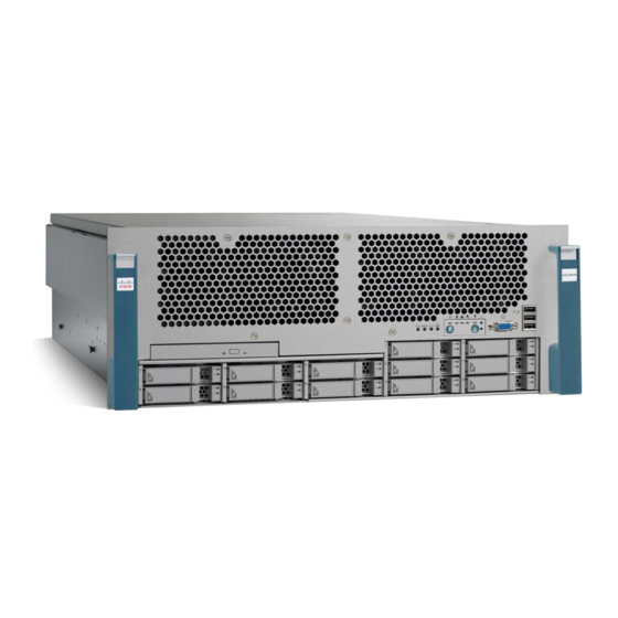
Cisco UCS C460 Server
Installation and Service Guide
Covers Server Generation M1 and Generation M2
November 13, 2013
Americas Headquarters
Cisco Systems, Inc.
170 West Tasman Drive
San Jose, CA 95134-1706
USA
http://www.cisco.com
Tel: 408 526-4000
800 553-NETS (6387)
Fax: 408 527-0883
Text Part Number: OL-22326-01
Advertisement
Table of Contents

Related Manuals for Cisco UCS C460


Summary of Contents for Cisco UCS C460
- Page 1 Cisco UCS C460 Server Installation and Service Guide Covers Server Generation M1 and Generation M2 November 13, 2013 Americas Headquarters Cisco Systems, Inc. 170 West Tasman Drive San Jose, CA 95134-1706 http://www.cisco.com Tel: 408 526-4000 800 553-NETS (6387) Fax: 408 527-0883...
- Page 2 Modifications to this product not authorized by Cisco could void the FCC approval and negate your authority to operate the product. The Cisco implementation of TCP header compression is an adaptation of a program developed by the University of California, Berkeley (UCB) as part of UCB’s public domain version of the UNIX operating system.
-
Page 3: Table Of Contents
Using a Clear CMOS Jumper on Header J5C2 2-17 Maintaining the Server C H A P T E R Server Monitoring and Management Tools Cisco Integrated Management Interface (CIMC) Server Configuration Utility Cisco UCS C460 Server Installation and Service Guide OL-22326-01... - Page 4 Replacing a PCIe Card in a Hot-Swappable Slot 3-40 Special Considerations for Cisco UCS Virtual Interface Cards 3-42 Special Considerations for Cisco UCS Fusion ioDrive2 Storage Accelerator Cards 3-42 Installing Multiple PCIe Cards and Resolving Limited Resources 3-43 Installing an NVIDIA Tesla C2050 GPU Card...
- Page 5 LSI MegaRAID SAS 9240-8i PCIe Card LSI MegaRAID SAS 9260-8i PCIe Card Restoring RAID Configuration After Replacing a RAID Controller For More Information Installation for Cisco UCS Integration A P P E N D I X Cisco UCS C460 Server Installation and Service Guide OL-22326-01...
- Page 6 Contents Cisco UCS C460 Server Installation and Service Guide OL-22326-01...
-
Page 7: Preface
Preface This preface describes the audience, organization, and conventions of the Cisco UCS C460 Server Installation and Service Guide. It also provides information about how to obtain related documentation. Related Documentation The documentation set for the Cisco Unified Computing System (UCS) C-Series rack-mount servers is... -
Page 8: Conventions
Tämä varoitusmerkki merkitsee vaaraa. Tilanne voi aiheuttaa ruumiillisia vammoja. Ennen kuin käsittelet laitteistoa, huomioi sähköpiirien käsittelemiseen liittyvät riskit ja tutustu onnettomuuksien yleisiin ehkäisytapoihin. Turvallisuusvaroitusten käännökset löytyvät laitteen mukana toimitettujen käännettyjen turvallisuusvaroitusten joukosta varoitusten lopussa näkyvien lausuntonumeroiden avulla. SÄILYTÄ NÄMÄ OHJEET Cisco UCS C460 Server Installation and Service Guide viii OL-22326-01... - Page 9 Utilize o número da instrução fornecido ao final de cada aviso para localizar sua tradução nos avisos de segurança traduzidos que acompanham este dispositivo. GUARDE ESTAS INSTRUÇÕES Cisco UCS C460 Server Installation and Service Guide OL-22326-01...
- Page 10 Använd det nummer som finns i slutet av varje varning för att hitta dess översättning i de översatta säkerhetsvarningar som medföljer denna anordning. SPARA DESSA ANVISNINGAR Cisco UCS C460 Server Installation and Service Guide OL-22326-01...
- Page 11 Brug erklæringsnummeret efter hver advarsel for at finde oversættelsen i de oversatte advarsler, der fulgte med denne enhed. GEM DISSE ANVISNINGER Cisco UCS C460 Server Installation and Service Guide OL-22326-01...
- Page 12 Preface Cisco UCS C460 Server Installation and Service Guide OL-22326-01...
-
Page 13: Obtaining Documentation And Submitting A Service Request
Obtaining Documentation and Submitting a Service Request For information on obtaining documentation, submitting a service request, and gathering additional information, see the monthly What’s New in Cisco Product Documentation, which also lists all new and revised Cisco technical documentation, at: http://www.cisco.com/en/US/docs/general/whatsnew/whatsnew.html... - Page 14 Preface Cisco UCS C460 Server Installation and Service Guide OL-22326-01...
-
Page 15: Chapter 1 Overview
This chapter provides an overview of the Cisco UCS C460 server features. The Cisco UCS C460 server is a part of the Cisco UCS C-Series rack-mount server family. It is a high-performance, high-memory-capacity server designed with the performance and reliability to power compute-intensive, enterprise-critical standalone applications and virtualized workloads.It operates in a... - Page 16 10G SFP+ LOM ports, two total 1G LOM ports, two total 10 Serial connector 10/100 Management ports M1 and M2 11 PCIe slots 1 through 10 (left to right as 12 Power supply LEDs shown) Cisco UCS C460 Server Installation and Service Guide OL-22326-01...
- Page 17 Chassis Four rack-unit (4RU) chassis Processors • Cisco UCS C460 M1 server: Either 2 or 4 Intel Xeon 7500 Series processors. • Cisco UCS C460 M2 server: Either 2 or 4 Intel E7-4800 or E7-8800 Series processors. Two-CPU configurations require 2 power supplies and 4-CPU configurations require 4 power supplies.
- Page 18 850W power supply during the failure and hot-swap. For more information about your server’s power consumption, consult with your Cisco sales representative or use the power calculator accessible at the Unified Computing System Partner Resource Center: http://www.ciscoprc.com/resourcelib.asp?id=937...
-
Page 19: Chapter 2 Installing The Server
Use the statement number provided at the end of each warning to locate its translation in the translated safety warnings that accompanied this device. Statement 1071 SAVE THESE INSTRUCTIONS Cisco UCS C460 Server Installation and Service Guide OL-22326-01... -
Page 20: Unpacking And Inspecting The Server
Model and serial number of the damaged unit Description of damage • Effect of damage on the installation • Figure 2-1 Shipping Box Contents Server Drivers and utilities disk Power cord (optional, up to four) Documentation Cisco UCS C460 Server Installation and Service Guide OL-22326-01... -
Page 21: Preparing For Server Installation
Avoid UPS types that use ferroresonant technology. These UPS types can become unstable with systems Caution such as the Cisco UCS, which can have substantial current draw fluctuations from fluctuating data traffic patterns. Cisco UCS C460 Server Installation and Service Guide... -
Page 22: Rack Requirements
Cisco. Equipment Requirements The slide rails supplied by Cisco Systems do not require any tools for installation, but you might want to use a tape measure and level to help level the slide rails during installation. -
Page 23: Installing The Server In A Rack
Installing the Slide Rail Assemblies in the Rack Rack posts Rear mounting pegs and locking clip Slide rail assembly Front mounting pegs and locking clip Attach the second slide-rail assembly to the opposite side of the rack. Cisco UCS C460 Server Installation and Service Guide OL-22326-01... - Page 24 Attach the blue clip connector (item 3) to the right slide rail. Attach the metal connector (item 1) to the rear of the mounting bracket that is attached to the right side of the server. Cisco UCS C460 Server Installation and Service Guide OL-22326-01...
- Page 25 Figure 2-4 Attaching the Cable Management Arm Metal connector Connector A Blue clip connector Square metal connector with blue tab Connector B Step 5 Continue with the Initial Server Setup, page 2-8. Cisco UCS C460 Server Installation and Service Guide OL-22326-01...
-
Page 26: Initial Server Setup
DHCP is enabled. Shared LOM EXT mode enables the 1-Gb Ethernet ports and the ports on any installed Cisco virtual interface card (VIC) to access the Cisco Integrated Management Interface (CIMC). If you want to use the dedicated management ports to access the CIMC, you can... - Page 27 Cisco card connection is not getting its IP address from a Cisco UCS Manager system because the server is in standalone mode, further DHCP requests from the Cisco card are disabled. Use the Cisco Card NIC mode if you want to connect to the CIMC through a Cisco card in standalone mode.
- Page 28 Cisco Step 6 UCS C-Series Rack-Mount Server CLI Configuration Guide for instructions on using those interfaces. The links to these documents are in the C-Series documentation roadmap: http://www.cisco.com/go/unifiedcomputing/c-series-doc Cisco UCS C460 Server Installation and Service Guide 2-10 OL-22326-01...
-
Page 29: Nic Modes And Nic Redundancy Settings
LOM and Cisco Card interfaces are both enabled. In this mode, DHCP replies are returned to both the shared LOM ports and the Cisco card ports. If the system determines that the Cisco card connection is not getting its IP address from a Cisco UCS Manager system because the server is in standalone mode, further DHCP requests from the Cisco card are disabled. -
Page 30: Using The 10 Gb Ports
The driver firmware allows you to change the PHY link priority to the SFP+ ports, or to disable the PHY links for either the SFP+ or the 10GBase-T ports. Consult with your Cisco service provider for details of this advanced procedure. -
Page 31: System Bios And Cimc Firmware
Your system firmware must be at minimum level 1.2 to use the Cisco Host Upgrade Utility. If Note your firmware is prior to level 1.2, you must use the methods below to update the BIOS and CIMC firmware individually. -
Page 32: Accessing The System Bios
Using a Clear BIOS Admin Password Jumper on Header J5C3, page 2-16 • Using a Clear CMOS Jumper on Header J5C2, page 2-17 Figure 2-6 Service Jumper Locations Header J6D1 (BIOS recovery) Header J5C3 (clear BIOS password) Header J5C2 (clear CMOS) Cisco UCS C460 Server Installation and Service Guide 2-14 OL-22326-01... -
Page 33: Using A Bios Recovery Jumper On Header J6D1
Step 14 Reinstall the top cover. Step 15 Replace the server in the rack, replace power cords and any other cables, then power on the server by pressing the Power button. Cisco UCS C460 Server Installation and Service Guide 2-15 OL-22326-01... -
Page 34: Using A Clear Bios Admin Password Jumper On Header J5C3
If you do not remove the jumper, the password is cleared every time you power-cycle the server. Replace the top cover. Step 10 Step 11 Replace the server in the rack, replace cables, and then power on the server by pressing the Power button. Cisco UCS C460 Server Installation and Service Guide 2-16 OL-22326-01... -
Page 35: Using A Clear Cmos Jumper On Header J5C2
Replace the top cover. Step 6 Replace the server in the rack, replace cables, and then power on the server by pressing the Power Step 7 button. Cisco UCS C460 Server Installation and Service Guide 2-17 OL-22326-01... - Page 36 Chapter 2 Installing the Server Motherboard Jumpers for Clearing BIOS Settings Cisco UCS C460 Server Installation and Service Guide 2-18 OL-22326-01...
-
Page 37: Chapter 3 Maintaining The Server
Configuring some RAID configurations • Installing operating systems This utility is shipped with new servers on CD. You can also download the ISO from Cisco.com. See the user documentation for this utility at the following URL: http://www.cisco.com/en/US/docs/unified_computing/ucs/sw/ucsscu/user/guide/20/SCUUG20.html Cisco UCS C460 Server Installation and Service Guide... -
Page 38: Status Leds And Buttons
DVD drive activity LED Hard drive fault LED Power supply fault LED Memory fault LED CPU fault LED Network activity LED Operations panel (see Operations Panel LEDs and Buttons, page 3-4). Cisco UCS C460 Server Installation and Service Guide OL-22326-01... - Page 39 Green and blinking —The Ethernet link is active. • Green and steady—The Ethernet link is detected but not active. The blink rate gets faster as network activity increases. Operations panel LEDs Operations Panel LEDs and Buttons, page 3-4. Cisco UCS C460 Server Installation and Service Guide OL-22326-01z...
-
Page 40: Operations Panel Leds And Buttons
Amber, blinking—At least one fan module has a severe fault. • Power status Off—The server is in standby power mode or no power is present. • Green—The server is in main power mode. • Cisco UCS C460 Server Installation and Service Guide OL-22326-01... -
Page 41: Rear Panel Leds And Buttons
Power supply AC input LED Green and steady—The AC power cord is plugged in and the power is present • Green and blinking—The AC power cord is not plugged in. • Cisco UCS C460 Server Installation and Service Guide OL-22326-01z... -
Page 42: Preparing For Server Component Installation
Graceful shutdown—Press and release the Power button. The operating system will perform a • graceful shutdown and the server goes to standby mode, which is indicated by the Power Status LED being off. Cisco UCS C460 Server Installation and Service Guide OL-22326-01... -
Page 43: Removing And Replacing The Server Top Cover
Slide the cover toward the front of the server until it stops at the front panel and the green buttons lock. Figure 3-4 Removing the Top Cover Green release buttons Rear of the server Cisco UCS C460 Server Installation and Service Guide OL-22326-01z... -
Page 44: Replaceable Component Locations
13 PCIe connector 10 (10 of 10) CMOS battery See also Figure 3-27 on page 3-38 for all slot locations and details. CPUs and heat sinks (up to 4, shown without CPU cage) Cisco UCS C460 Server Installation and Service Guide OL-22326-01... -
Page 45: Installing Or Replacing Server Components
Replacing Hard Drives or Solid State Drives, page 3-33 • Replacing a DVD Drive, page 3-36 • Replacing a PCIe Card, page 3-38 • Replacing a Trusted Platform Module (TPM), page 3-50 • Cisco UCS C460 Server Installation and Service Guide OL-22326-01z... -
Page 46: Replacing Power Supplies
850W power supply during the failure and hot-swap. For more information about your server’s power consumption, consult with your Cisco sales representative or use the power calculator accessible at the Unified Computing System Partner Resource Center: http://www.ciscoprc.com/resourcelib.asp?id=937... -
Page 47: Power Supply Cold Redundancy
AC power, but the power consumption can be satisfied by power supply 1, then power supply 2 is put into a standby state. Cisco UCS C460 Server Installation and Service Guide 3-11 OL-22326-01z... -
Page 48: Replacing The I/O Riser
Push the green retaining clip down until it locks over the top of the I/O riser. Replace the top cover. Replace the server in the rack, replace cables, and then power on the server by pressing the Power button. Cisco UCS C460 Server Installation and Service Guide 3-12 OL-22326-01... -
Page 49: Replacing An Internal Flash Eusb Drive
Slide the server out the front of the rack far enough so that you can remove the top cover. Note You might have to detach cables from the rear panel to provide clearance. Cisco UCS C460 Server Installation and Service Guide 3-13 OL-22326-01z... - Page 50 Replace the server in the rack, replace cables, and then power on the server by pressing the Power button. Figure 3-8 Removing and Replacing the eUSB Drive eUSB connectors on motherboard (two) eUSB drive, showing orientation of hole for securing screw Cisco UCS C460 Server Installation and Service Guide 3-14 OL-22326-01...
-
Page 51: Enabling Or Disabling The Internal Usb Port
Scroll to USB Port: Internal, press Enter, and then select either Enabled or Disabled from the pop-up Step 5 menu. Press F10 to save and exit the utility. Step 6 Cisco UCS C460 Server Installation and Service Guide 3-15 OL-22326-01z... -
Page 52: Replacing A Sas Riser (Raid Controller)
Replace the server in the rack, replace cables, and then power on the server by pressing the Power button. Restore the RAID configuration on your drives to the new mass storage controller. Step 3 Restoring RAID Configuration After Replacing a RAID Controller, page C-4. Cisco UCS C460 Server Installation and Service Guide 3-16 OL-22326-01... - Page 53 SAS riser Figure 3-10 SAS Riser Card Connectors SAS cable connectors LSI BBU connector JT3 JT6 = Ports 0 - 3 (on LSI 9260-8i only) JT7 = Ports 4 - 7 Cisco UCS C460 Server Installation and Service Guide 3-17 OL-22326-01z...
-
Page 54: Replacing The Sas Riser Battery Backup Unit
3-26. Slide the battery assembly toward the front of the chassis to disengage its retaining clips from the chassis wall slots. Disconnect the cable that is attached to the BBU. Cisco UCS C460 Server Installation and Service Guide 3-18 OL-22326-01... - Page 55 Replace the server in the rack, replace cables, and then power on the server by pressing the Power button. Figure 3-11 Removing and Replacing the RAID Battery Assembly BBU position on inside chassis wall BBU retaining clips Cisco UCS C460 Server Installation and Service Guide 3-19 OL-22326-01z...
-
Page 56: Replacing The Motherboard Cmos Battery
Replace the I/O riser. See Replacing the I/O Riser, page 3-12. Replace the top cover. Replace the server in the rack, replace cables, and then power on the server by pressing the Power button. Cisco UCS C460 Server Installation and Service Guide 3-20 OL-22326-01... - Page 57 Chapter 3 Maintaining the Server Installing or Replacing Server Components Figure 3-12 Removing and Replacing the Motherboard CMOS Battery CMOS battery socket Retaining clip Cisco UCS C460 Server Installation and Service Guide 3-21 OL-22326-01z...
-
Page 58: Replacing Cpus And Heatsinks
Additional CPU-Related Parts To Order With RMA Replacement Motherboards When a return material authorization (RMA) of the motherboard or CPU is done on a Cisco UCS C-series server, there are additional parts that might not be included with the CPU or motherboard spare bill of materials (BOM). - Page 59 Damage to the heatsink surface can damage the heat transferring properties of the heatsink. Apply the supplied preparation solution to the center bottom of the heatsink, where the new thermal pad will be applied. Cisco UCS C460 Server Installation and Service Guide 3-23 OL-22326-01z...
- Page 60 Locations of CPU Cage Screws CPU cage screw locations (six) on Memory risers (eight) motherboard (cage not shown) Memory riser dividers (eight) CPU heatsink CPU heatsink captive screws (two on each heatsink) Cisco UCS C460 Server Installation and Service Guide 3-24 OL-22326-01...
- Page 61 Chapter 3 Maintaining the Server Installing or Replacing Server Components Figure 3-15 Removing a CPU and Heatsink CPU retaining lever CPU retaining lid Heatsink Heatsink captive screws (two) Cisco UCS C460 Server Installation and Service Guide 3-25 OL-22326-01z...
-
Page 62: Replacing Memory Risers
Ensure that the riser release latches are in the open position. Align the riser with the empty motherboard connector. Push the riser into the connector until it is seated and the open release levers engage. Cisco UCS C460 Server Installation and Service Guide 3-26 OL-22326-01... - Page 63 Press the attention button, then wait until the attention LED turns off. Replace the top cover. Replace the server in the rack and replace any cables. Figure 3-17 Removing and Replacing Memory Risers Memory riser release buttons Memory riser release latches Cisco UCS C460 Server Installation and Service Guide 3-27 OL-22326-01z...
-
Page 64: Replacing Dimms
Buffer 1, channel 1: slots 1B and 1D • Buffer 1, channel 2: slots 1A and 1C • Buffer 2, channel 1: slots 2B and 2D • Buffer 2, channel 2: slots 2A and 2C Cisco UCS C460 Server Installation and Service Guide 3-28 OL-22326-01... - Page 65 DIMMs. When using rank sparing, available memory equals total installed memory minus the size of the • spared ranks. Rank size equals DIMM size divided by the number of ranks. Cisco UCS C460 Server Installation and Service Guide 3-29 OL-22326-01z...
-
Page 66: Dimm Installation Procedure
If you cannot safely view and access the component, remove the server from the rack. Caution Remove the top cover as described in “Removing and Replacing the Server Top Cover” section on page 3-7. Cisco UCS C460 Server Installation and Service Guide 3-30 OL-22326-01... - Page 67 Press the attention button on the top of the memory riser, then wait until the attention LED turns off (see Figure 3-20). Replace the top cover. Replace the server in the rack and replace any cables. Figure 3-21 Removing and Replacing DIMMs DIMM slots Memory riser Cisco UCS C460 Server Installation and Service Guide 3-31 OL-22326-01z...
-
Page 68: Replacing Fan Modules
Press down on the top corners of the fan module until the connector is fully seated and the release latches lock in place. Replace the top cover. Replace the server in the rack. Cisco UCS C460 Server Installation and Service Guide 3-32 OL-22326-01... -
Page 69: Replacing Hard Drives Or Solid State Drives
SSDs. Note Cisco recommends following the industry-standard practice of using drives of the same capacity when configuring RAID volumes. If you use drives of different capacities, the usable portion of the smallest drive will be used on all drives of the RAID volume. - Page 70 Chapter 3 Maintaining the Server Installing or Replacing Server Components http://www.cisco.com/en/US/products/ps10493/products_data_sheets_list.html Cisco UCS C460 Server Installation and Service Guide 3-34 OL-22326-01...
- Page 71 HDD 2 HDD 3 HDD 4 HDD 5 HDD 6 HDD 7 HDD 8 HDD 9 HDD 10 HDD 11 HDD 12 Ejector lever Release button Drive tray securing screws Cisco UCS C460 Server Installation and Service Guide 3-35 OL-22326-01z...
-
Page 72: Replacing A Dvd Drive
Replace all memory riser dividers. Replace all memory risers. Replace the top cover. Replace the server in the rack, replace cables, and then power on the server by pressing the Power button. Cisco UCS C460 Server Installation and Service Guide 3-36 OL-22326-01... - Page 73 Chapter 3 Maintaining the Server Installing or Replacing Server Components Figure 3-26 Removing and Replacing the DVD Drive DVD drive bay Rear of DVD drive Cisco UCS C460 Server Installation and Service Guide 3-37 OL-22326-01z...
-
Page 74: Replacing A Pcie Card
Chapter 3 Maintaining the Server Installing or Replacing Server Components Replacing a PCIe Card If you are installing a Cisco UCS Virtual Interface Card, there are prerequisite considerations. See Note Special Considerations for Cisco UCS Virtual Interface Cards, page 3-42. - Page 75 You might have to detach cables from the rear panel to provide clearance. Note Caution If you cannot safely view and access the component, remove the server from the rack. Cisco UCS C460 Server Installation and Service Guide 3-39 OL-22326-01z...
- Page 76 3-7. Remove any cables from the ports of the PCIe card that you are replacing. Label the cables when you disconnect them to aid correct connection to the new card. Cisco UCS C460 Server Installation and Service Guide 3-40 OL-22326-01...
- Page 77 Press the lightpipe switch that is on top of the plastic divider for the hot-swappable PCIe slot. Wait for the LED to turn on to ensure that the PCIe slot receives power. Replace the top cover. Replace the server in the rack and replace cables. Cisco UCS C460 Server Installation and Service Guide 3-41 OL-22326-01z...
-
Page 78: Special Considerations For Cisco Ucs Virtual Interface Cards
1. See PCIe Slots, page 3-38. 2. The Cisco UCS VIC1225T is not supported for UCS integration at this time. Special Considerations for Cisco UCS Fusion ioDrive2 Storage Accelerator Cards Table 3-6 describes the requirements for the supported Cisco UCS Fusion ioDrive2 cards. -
Page 79: Installing Multiple Pcie Cards And Resolving Limited Resources
Utility provides the setup options to enable or disable the Option ROMs at the PCIe slot level for the PCIe expansion slots and at the port level for the onboard NICs. These options can be found in the BIOS Setup Utility Advanced PCI Configuration page (see Figure 3-28). Cisco UCS C460 Server Installation and Service Guide 3-43 OL-22326-01z... - Page 80 PCIe boot devices might not be accessible from the BIOS. • PCIe option ROMs might report initialization errors. These errors are seen before the BIOS hands • control to the operating system. The keyboard might not work. • Cisco UCS C460 Server Installation and Service Guide 3-44 OL-22326-01...
- Page 81 – Slot 5: IOH 1 – Slot 6: IOH 1 – Slot 7: IOH 1 – Slot 8: IOH 0 – Slot 9: IOH 1 – Slot 10: IOH 1 Cisco UCS C460 Server Installation and Service Guide 3-45 OL-22326-01z...
-
Page 82: Installing An Nvidia Tesla C2050 Gpu Card
VGA connectors on the server instead. Cisco ships an accessory kit (UCSC-GPU_N01-C460) that includes two adapters that you must use to customize the card for installation in the Cisco C460 M2 server. Each kit includes the following components (see Figure... - Page 83 This pin is on the front end of the divider assembly where it touches the motherboard (see Figure 3-30). Figure 3-30 Cisco C2050 GPU Card Slots PCIe slot 5 Release pin on front of divider assembly PCIe slot 6 Cisco UCS C460 Server Installation and Service Guide 3-47 OL-22326-01z...
- Page 84 Close the two green PCIe retainer latches for slots 5 and 6 over the top of the rear-panel faceplate. Tighten the two thumbscrews on the front bracket of the card to secure it to the CPU cage. Cisco UCS C460 Server Installation and Service Guide 3-48...
- Page 85 Power button. Figure 3-32 Installing and Cabling the GPU Card Six-pin connector to GPU card Ten-pin female connector to PCIe power cable Ten-pin male connector to motherboard socket J166 Cisco UCS C460 Server Installation and Service Guide 3-49 OL-22326-01z...
-
Page 86: Replacing A Trusted Platform Module (Tpm)
Log into the BIOS Setup utility with your BIOS Administrator password. Select the Advanced tab. Select Trusted Computing to open the TPM Security Device Configuration screen. Verify that TPM SUPPORT is Enabled. Cisco UCS C460 Server Installation and Service Guide 3-50 OL-22326-01... -
Page 87: Enabling The Intel Trusted Execution Technology (Txt) Feature For The Tpm
Reboot the server. Watch during bootup for the F2 prompt, and then press F2 to enter BIOS setup. Log in to the BIOS Setup utility with your BIOS Administrator password. Cisco UCS C460 Server Installation and Service Guide 3-51 OL-22326-01z... - Page 88 Watch during bootup for the F2 prompt, and then press F2 to enter BIOS setup. Select the Advanced tab. Select Intel TXT(LT-SX) Configuration and verify that TXT Support, VT-d Support, and VT Support are Enabled. Cisco UCS C460 Server Installation and Service Guide 3-52 OL-22326-01...
-
Page 89: Appendix
27.7 in (704 mm) Weight 110.23 lbs (50 kg) The Cisco UCS C460 server weighs approximately 110 pounds, or 50 kilograms, when fully loaded with Caution components. We recommend that you use a minimum of two people when lifting the server. Attempting to lift the Cisco UCS C460 server alone could result in personal injury or equipment damage. -
Page 90: Environmental Specifications
Power supply output voltage Main power: 12 VDC Standby power: 3.3 VDC You can get more specific power information for your exact server configuration by using the Cisco UCS Power Calculator: http://www.cisco.com/assets/cdc_content_elements/flash/dataCenter/cisco_ucs_power_calculator/ Cisco UCS C460 Server Installation and Service Guide... -
Page 91: Appendix
Power Cord, 250 VAC 10 A M 2511 Plug Europe SFS-250V-10A-ID Figure B-5 Power Cord, 250 VAC 16A EL-208 Plug South Africa, United Arab Emirates, India SFS-250V-10A-IS Figure B-6 Power Cord, 250 VAC 10 A SI32 Plug Israel Cisco UCS C460 Server Installation and Service Guide OL-22326-01... - Page 92 Cabinet Jumper Power Cord, 250 VAC 10 A, C13-C14 Connectors CAB-C13-C14-2M Figure B-14 Cabinet Jumper Power Cord, 250 VAC 10 A, C13-C14 Connectors CAB-C13-C14-AC Figure B-15 Cabinet Jumper Power Cord, 250 VAC 10 A, C13-C14 Connectors Cisco UCS C460 Server Installation and Service Guide OL-22326-01...
-
Page 93: Ac Power Cord Illustrations
Cordset rating: 10 A, 250 V/500V Length: 2500mm Connector: Plug: EL 701C EL 206 (IEC 60320/C15) A.S. 3112-2000) Figure B-3 SFS-250V-10A-CN Cordset rating 10A, 250V Plug: (2500 mm) EL 218 (CCEE GB2009) Connector: EL 701 (IEC60320/C13) Cisco UCS C460 Server Installation and Service Guide OL-22326-01... - Page 94 Figure B-5 SFS-250V-10A-ID Cordset rating 16A, 250V Plug: (2500mm) EL 208 Connector: EL 701 Figure B-6 SFS-250V-10A-IS Cordset rating 10A, 250V/500V MAX (2500 mm) Connector: EL 701B Plug: (IEC60320/C13) EL 212 (SI-32) Cisco UCS C460 Server Installation and Service Guide OL-22326-01...
- Page 95 MP232-R Connector: IEC 60320 C15 Figure B-9 CAB-9K10A-UK Cordset rating: 10 A, 250 V/500 V MAX Length: 2500mm Connector: EL 701C Plug: EL 210 (EN 60320/C15) (BS 1363A) 13 AMP fuse Cisco UCS C460 Server Installation and Service Guide OL-22326-01...
- Page 96 Figure B-11 CAB-N5K6A-NA Cordset rating: 10 A, 250 V Length: 8.2 ft Plug: NEMA 6-15P Connector: IEC60320/C13 Figure B-12 CAB-9K12A-NA Cordset rating 13A, 125V (8.2 feet) (2.5m) Plug: Connector: IEC60320/C15 NEMA 5-15P Cisco UCS C460 Server Installation and Service Guide OL-22326-01...
- Page 97 CAB-C13-C14-2M, Jumper Power Cord (2 m) Cordset rating 10A, 250V (2.0 m) Connector: Plug: HS10S SS10A Figure B-15 CAB-C13-C14-AC, Jumper Power Cord (3 m) Cordset rating 10A, 250V (3.0 m) Connector: Plug: HS10S SS10A Cisco UCS C460 Server Installation and Service Guide OL-22326-01...
- Page 98 Appendix B Power Cord Specifications Supported Power Cords and Plugs Cisco UCS C460 Server Installation and Service Guide OL-22326-01...
-
Page 99: Appendix
1. You can mix SAS and SATA drives when using an LSI SAS3081E-R card. However, you cannot mix SAS and SATA drives within a volume. 2. You can mix SAS and SATA drives when using an LSI MegaRAID card. However, you cannot mix SAS and SATA drives within a volume. Cisco UCS C460 Server Installation and Service Guide OL-22326-01... -
Page 100: Mixing Drive Types In Raid Groups
• Cisco UCS C460 Server Cabling, page C-4 • Cable Routing The red line in Figure C-1 shows the recommended cable routing path from the backplane to the SAS riser connectors. Cisco UCS C460 Server Installation and Service Guide OL-22326-01... - Page 101 Appendix C RAID Controller Considerations RAID Controller Cabling Figure C-1 RAID Controller Connectors 1 SAS riser slot (RAID controller) 2 Drive backplane Cisco UCS C460 Server Installation and Service Guide OL-22326-01...
-
Page 102: Cisco Ucs C460 Server Cabling
Press any key to continue, or ‘C’ to load the configuration utility. Cisco UCS C460 Server Installation and Service Guide OL-22326-01... -
Page 103: For More Information
For basic information about RAID and for using the utilities for the RAID controller cards, see the Cisco UCS Servers RAID Guide. Full LSI documentation is also available: LSI MegaRAID SAS Software User’s Guide (for LSI MegaRAID) • http://www.cisco.com/en/US/docs/unified_computing/ucs/3rd-party/lsi/mrsas/userguide/LSI_MR_SAS_SW_UG.pdf Cisco UCS C460 Server Installation and Service Guide OL-22326-01... - Page 104 Appendix C RAID Controller Considerations For More Information Cisco UCS C460 Server Installation and Service Guide OL-22326-01...
-
Page 105: Appendix
The Cisco UCS integration instructions have been moved to the integration guides found here: Cisco UCS C-Series Server Integration with UCS Manager Guides Refer to the guide that is for the version of Cisco UCS Manager that you are using. Cisco UCS C460 Server Installation and Service Guide... - Page 106 Appendix D Installation for Cisco UCS Integration Cisco UCS C460 Server Installation and Service Guide OL-22326-01...
Need help?
Do you have a question about the UCS C460 and is the answer not in the manual?
Questions and answers