Table of Contents
Advertisement
Quick Links
Advertisement
Table of Contents

Related Manuals for Cisco UCS C420


Summary of Contents for Cisco UCS C420
- Page 1 Cisco UCS C420 Server Installation and Service Guide Covers Server Generation M3 October 29, 2013 Americas Headquarters Cisco Systems, Inc. 170 West Tasman Drive San Jose, CA 95134-1706 http://www.cisco.com Tel: 408 526-4000 800 553-NETS (6387) Fax: 408 527-0883 Text Part Number: OL-27640-01...
- Page 2 OR ITS SUPPLIERS HAVE BEEN ADVISED OF THE POSSIBILITY OF SUCH DAMAGES. CCVP, the Cisco logo, and Welcome to the Human Network are trademarks of Cisco Systems, Inc.; Changing the Way We Work, Live, Play, and Learn is a service mark of Cisco Systems, Inc.;...
-
Page 3: Table Of Contents
Procedure 1: Reboot With recovery.cap File 2-15 Procedure 2: Use BIOS Recovery DIP Switch and recovery.cap File 2-16 Maintaining the Server C H A P T E R Server Monitoring and Management Tools Cisco UCS C420 Server Installation and Service Guide OL-24342-01... - Page 4 Enabling a Cisco FlexFlash Virtual Drive 3-39 Booting a Cisco FlexFlash Virtual Drive 3-40 Monitoring and Managing a Cisco FlexFlash Drive 3-41 Synchronizing RAID After Installing a Second Cisco FlexFlash Drive 3-41 Cisco FlexFlash Drive Replacement Procedure 3-41 Replacing a PCIe Card 3-43...
- Page 5 Example 3—Two Expanders and One RAID Controller with Sixteen Drives Restoring RAID Configuration After Replacing a RAID Controller For More Information Installation for Cisco UCS Integration A P P E N D I X Cisco UCS C420 Server Installation and Service Guide OL-24342-01...
- Page 6 Contents Cisco UCS C420 Server Installation and Service Guide OL-24342-01...
- Page 7 Preface This preface describes the audience, organization, and conventions of the Cisco UCS C420 Server Installation and Service Guide. It also provides information about how to obtain related documentation. Audience This guide is for experienced network administrators who configure and maintain Cisco servers.
- Page 8 Tämä varoitusmerkki merkitsee vaaraa. Tilanne voi aiheuttaa ruumiillisia vammoja. Ennen kuin käsittelet laitteistoa, huomioi sähköpiirien käsittelemiseen liittyvät riskit ja tutustu onnettomuuksien yleisiin ehkäisytapoihin. Turvallisuusvaroitusten käännökset löytyvät laitteen mukana toimitettujen käännettyjen turvallisuusvaroitusten joukosta varoitusten lopussa näkyvien lausuntonumeroiden avulla. SÄILYTÄ NÄMÄ OHJEET Cisco UCS C420 Server Installation and Service Guide viii OL-27640-01...
- Page 9 Utilize o número da instrução fornecido ao final de cada aviso para localizar sua tradução nos avisos de segurança traduzidos que acompanham este dispositivo. GUARDE ESTAS INSTRUÇÕES Cisco UCS C420 Server Installation and Service Guide OL-27640-01...
- Page 10 Använd det nummer som finns i slutet av varje varning för att hitta dess översättning i de översatta säkerhetsvarningar som medföljer denna anordning. SPARA DESSA ANVISNINGAR Cisco UCS C420 Server Installation and Service Guide OL-27640-01...
- Page 11 Brug erklæringsnummeret efter hver advarsel for at finde oversættelsen i de oversatte advarsler, der fulgte med denne enhed. GEM DISSE ANVISNINGER Cisco UCS C420 Server Installation and Service Guide OL-27640-01...
- Page 12 Preface Cisco UCS C420 Server Installation and Service Guide OL-27640-01...
- Page 13 Preface Cisco UCS C420 Server Installation and Service Guide xiii OL-27640-01...
-
Page 14: Related Documentation
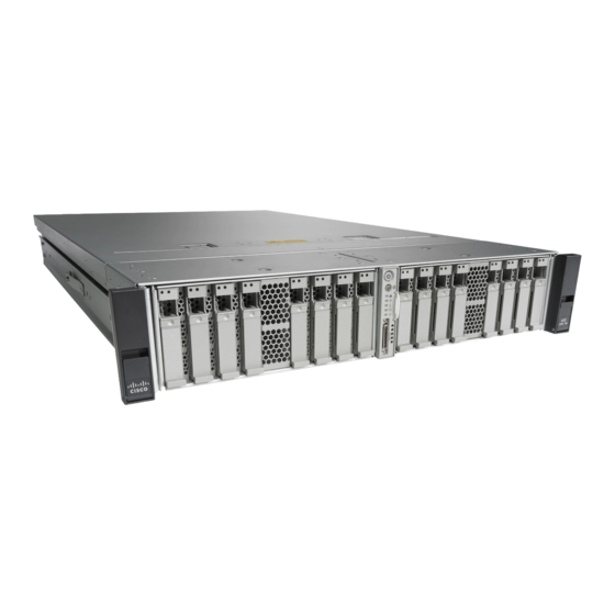
What’s New in Cisco Product Documentation at: http://www.cisco.com/en/US/docs/general/whatsnew/whatsnew.html. Subscribe to What’s New in Cisco Product Documentation, which lists all new and revised Cisco technical documentation, as an RSS feed and deliver content directly to your desktop using a reader application. The RSS feeds are a free service. - Page 15 C H A P T E R Overview of the Cisco UCS C420 Server This chapter provides an overview of the Cisco UCS C420 server. The figures in this chapter show an overview of external server features. Internal server features are shown in Figure 3-5 on page 3-10.
-
Page 16: Chapter 1 Overview Of The Cisco Uc C420 Server
Horizontal PCIe slot 7 on riser card 13 Rear identification button and LED (full-height, half-length, x16, with NCSI) Power supply 2 USB 2.0 ports (three) 10/100/1000 dedicated management Ethernet port (RJ-45) Cisco UCS C420 Server Installation and Service Guide OL-27640-01... - Page 17 This drive is preloaded with four virtual drives. The four virtual drives contain, respectively, the Cisco Server Configuration Utility, the Cisco Host Upgrade Utility, the Cisco C-Series server drivers set, and a blank VD on which you can install an OS or a hypervisor.
- Page 18 Pilot III BMC, running Cisco Integrated Management Controller (CIMC) firmware. management Depending on your CIMC settings, the CIMC can be accessed through the 10/100/1000 dedicated management ports, the 1-Gb LOM ports, or a Cisco virtual interface card. Video Resolution up to 1600 x1200, 16 bpp at 60 Hz. Up to 256 MB of video memory.
-
Page 19: Installing The Server
Use the statement number provided at the end of each warning to locate its translation in the translated safety warnings that accompanied this device. Statement 1071 SAVE THESE INSTRUCTIONS Cisco UCS C420 Server Installation and Service Guide OL-27640-01... -
Page 20: Chapter 2 Installing The Server
Model and serial number of the damaged unit • Description of damage • Effect of damage on the installation Figure 2-1 Shipping Box Contents Server Documentation Power cord (up to two) KVM cable Cisco UCS C420 Server Installation and Service Guide OL-27640-01... -
Page 21: Preparing For Server Installation
Avoid UPS types that use ferroresonant technology. These UPS types can become unstable with systems Caution such as the Cisco UCS, which can have substantial current draw fluctuations from fluctuating data traffic patterns. Cisco UCS C420 Server Installation and Service Guide... -
Page 22: Rack Requirements
The minimum vertical rack space per server must be two RUs, equal to 3.5 in. (88.9 mm). Equipment Requirements The slide rails supplied by Cisco Systems for this server do not require tools for installation if you install them in a rack that has square 0.38-inch (9.6 mm), round 0.28-inch (7.1 mm), or #12-24 UNC threaded holes. -
Page 23: Installing The Server In A Rack
Locking clip (one on each end of assembly) Attach the second slide-rail assembly to the opposite side of the rack. Ensure that the two slide-rail assemblies are level and at the same height with each other. Cisco UCS C420 Server Installation and Service Guide OL-27640-01... - Page 24 The inner rails are preattached to the sides of the server at the factory. You can order replacement Note inner rails if these are damaged or lost (Cisco PID UCSC-RAIL-2U-I). Align the inner rails that are attached to the server sides with the front ends of the empty slide rails.
- Page 25 INNER RAIL CMA tab attached to inner slide INNER RAIL CMA tab attached to inner slide rail on server rail on server Rear of left slide rail assembly OUTER RAIL CMA tab attached to outer slide rail Cisco UCS C420 Server Installation and Service Guide OL-27640-01...
-
Page 26: Initial Server Setup
This section describes how to power on the server, assign an IP address, and connect to server management when using the server in standalone mode. To use the server in a Cisco UCS integration, specific cabling and settings are required. See Installation for Cisco UCS Integration, page D-1. - Page 27 Cisco card connection is not getting its IP address from a Cisco UCS Manager system because the server is in standalone mode, further DHCP requests from the Cisco card are disabled. Use the Cisco Card NIC mode if you want to connect to the CIMC through a Cisco card in standalone mode.
- Page 28 The default user name for the server is admin. The default password is password. To manage the server, see the Cisco UCS C-Series Rack-Mount Server Configuration Guide or the Cisco UCS C-Series Rack-Mount Server CLI Configuration Guide for instructions on using those interfaces.
-
Page 29: Nic Modes And Nic Redundancy Settings
Cisco Card interfaces are both enabled. Note In this mode, DHCP replies are returned to both the shared LOM ports and the Cisco card ports. If the system determines that the Cisco card connection is not getting its IP address from a Cisco UCS Manager system because the server is in standalone mode, further DHCP requests from the Cisco card are disabled. -
Page 30: System Bios And Cimc Firmware
Cisco provides the Cisco Host Upgrade Utility (HUU) to assist with simultaneously upgrading the BIOS, CIMC, and other firmware to compatible levels. In this server, the HUU is included on the Cisco Flexible Flash card inside the server (see Replacing a Cisco Flexible Flash Drive, page 3-39). -
Page 31: Accessing The System Bios
Step 6 Follow the instructions on the Exit menu screen to save your changes and exit the setup utility (or press F10). You can exit without saving changes by pressing Esc. Cisco UCS C420 Server Installation and Service Guide 2-13 OL-27640-01... -
Page 32: Service Dip Switch
I/O riser in the server. Figure 2-5 DIP Switches on I/O Riser 1 2 3 4 5 6 7 8 DIP switch 2 for BIOS recovery (shown in default open position) Cisco UCS C420 Server Installation and Service Guide 2-14 OL-27640-01... -
Page 33: Using The Bios Recovery Dip Switch
During the BIOS update, the CIMC will shut down the server and the screen will be blank for about 10 minutes. Do not unplug the power cords during this update. The CIMC will power on the server after the update is complete. Cisco UCS C420 Server Installation and Service Guide 2-15 OL-27640-01... -
Page 34: Procedure 2: Use Bios Recovery Dip Switch And Recovery.cap File
Replace the top cover, replace the server in the rack, replace power cords and any other cables, and then Step 15 power on the server by pressing the Power button. Cisco UCS C420 Server Installation and Service Guide 2-16 OL-27640-01... -
Page 35: Server Monitoring And Management Tools
Server Monitoring and Management Tools Cisco Integrated Management Interface You can monitor the server inventory, health, and system event logs by using the built-in Cisco Integrated Management Controller (CIMC) GUI or CLI interfaces. See the user documentation for your firmware release at the following URL: http://www.cisco.com/en/US/products/ps10739/products_installation_and_configuration_guides_list.html... -
Page 36: Chapter 3 Maintaining The Server
Fan status LED Hard drive activity LED Temperature status LED Power button and Power status LED Power supply status LED Identification button and LED Network link activity LED System status LED Cisco UCS C420 Server Installation and Service Guide OL-27640-01... - Page 37 Green—The server is operating at normal temperature. • Amber, steady—One or more temperature sensors have exceeded a warning • threshold. Amber, blinking—One or more temperature sensors have exceeded a critical • threshold. Cisco UCS C420 Server Installation and Service Guide OL-27640-01...
-
Page 38: Rear-Panel Leds And Buttons
(present only if 10-Gb VIC is installed) 10/100/1000 Ethernet link speed 1-Gb Ethernet link speed 10/100/1000 Ethernet link status 1-Gb Ethernet link status 10 Rear identification button and LED System status Cisco UCS C420 Server Installation and Service Guide OL-27640-01... - Page 39 Green, blinking—Traffic is present on the active link. • 1-Gb Ethernet link speed Off—Link speed is 10 Mbps. • Amber—Link speed is 100 Mbps. • Green—Link speed is 1 Gbps. • Cisco UCS C420 Server Installation and Service Guide OL-27640-01...
- Page 40 Off—No link is present. • Green—Link is active. • Green, blinking—Traffic is present on the active link. Identification • Off—The identification LED is not in use. Blue—The identification LED is activated. • Cisco UCS C420 Server Installation and Service Guide OL-27640-01...
-
Page 41: Internal Diagnostic Leds
RTC battery fault LED on motherboard Cisco FlexFlash card fault LEDs on I/O riser Table 3-3 Internal Diagnostic LED States LED Name State Internal diagnostic LEDs (all) • Off—Component is functioning normally. • Amber—Component has failed. Cisco UCS C420 Server Installation and Service Guide OL-27640-01... -
Page 42: Preparing For Server Component Installation
Emergency shutdown—Press and hold the Power button for 4 seconds to force the main power off • and immediately enter standby mode. Disconnect the power cords from the power supplies in your server to completely power off the server. Step 3 Cisco UCS C420 Server Installation and Service Guide OL-27640-01... -
Page 43: Removing And Replacing The Server Top Cover
The cover should sit flat when the edge flanges are sitting in the grooves in the chassis. Slide the top cover toward the front cover panel until it stops and the release buttons lock. Figure 3-4 Removing the Top Cover Release buttons Front cover panel Cisco UCS C420 Server Installation and Service Guide OL-27640-01... -
Page 44: Replaceable Component Locations
16 RAID backup unit (supercap power module) PCIe riser 1 (horizontal PCIe slot 7) mounting location (two, on air baffle not shown in this view) Cisco UCS C420 Server Installation and Service Guide 3-10 OL-27640-01... -
Page 45: Color-Coded Touch Points
Installing a Trusted Platform Module, page 3-55 • Enabling the Intel Trusted Execution Technology Feature For the TPM, page 3-56 • Replacing Power Supplies, page 3-58 • Enabling or Disabling the Internal USB Port, page 3-59 Cisco UCS C420 Server Installation and Service Guide 3-11 OL-27640-01... -
Page 46: Replacing Hard Drives Or Solid State Drives
You can mix hard drives and SSDs in the same server. However, you cannot configure a logical • volume (virtual drive) that contains a mix of hard drives and SSDs. When you create a logical volume, it must contain all hard drives or all SSDs. Cisco UCS C420 Server Installation and Service Guide 3-12 OL-27640-01... -
Page 47: Drive Replacement Procedure
Push the tray into the slot until it touches the backplane, and then close the ejector lever to lock the drive in place. Figure 3-7 Removing and Replacing Hard Drives Release button Drive tray securing screws (4) Ejector lever Cisco UCS C420 Server Installation and Service Guide 3-13 OL-27640-01... -
Page 48: Replacing A Modular Drive Bay Assembly
Drive Bay Assembly and Transition Card (Two Versions) Chassis drive bay module (rear view) Transition card securing screws (two) Drive backplane Transition card connector to motherboard Transition card (nonexpander version) Transition card (expander version) Cisco UCS C420 Server Installation and Service Guide 3-14 OL-27640-01... - Page 49 Replace the fan tray as described in Replacing a Fan Tray, page 3-19. Replace the top cover. Replace the server in the rack, replace cables, and then power on the server by pressing the Power button. Cisco UCS C420 Server Installation and Service Guide 3-15 OL-27640-01...
- Page 50 PCle 1 DIMM P DIMM B DIMM N DIMM A Transition card on chassis floor Transition card connector to motherboard (shown with fan tray removed) Transition card securing screws (2) Cisco UCS C420 Server Installation and Service Guide 3-16 OL-27640-01...
-
Page 51: Replacing Fan Modules
Press down on the top corners of the fan module until the connector is fully seated and the release latches lock in place. Replace the top cover. Replace the server in the rack. Cisco UCS C420 Server Installation and Service Guide 3-17 OL-27640-01... - Page 52 Chapter 3 Maintaining the Server Installing or Replacing Server Components Figure 3-11 Removing and Replacing Fan Modules Fan tray Connector location on underside of fan module Fan module release latches Cisco UCS C420 Server Installation and Service Guide 3-18 OL-27640-01...
-
Page 53: Replacing A Fan Tray
Tighten the three captive thumbscrews that secure the tray to the motherboard and chassis. Replace the top cover. Replace the server in the rack, replace cables, and then power on the server by pressing the Power button. Cisco UCS C420 Server Installation and Service Guide 3-19 OL-27640-01... - Page 54 Maintaining the Server Installing or Replacing Server Components Figure 3-12 Removing and Replacing a Fan Tray Captive thumbscrews (3) Motherboard connector location Guide pegs (2 on each end of fan tray) Cisco UCS C420 Server Installation and Service Guide 3-20 OL-27640-01...
-
Page 55: Replacing Dimms
DIMMs and their sockets are fragile and must be handled with care to avoid damage during installation. Caution Cisco does not support third-party DIMMs. Using non-Cisco DIMMs in the server might result in system problems or damage to the motherboard. - Page 56 Channel E CPU4 CPU1 Channel R Channel C CPU4 CPU1 Channel S Channel D CPU 4 CPU 1 CPU4 CPU1 Channel P Channel B CPU4 CPU1 Channel N Channel A Cisco UCS C420 Server Installation and Service Guide 3-22 OL-27640-01...
- Page 57 CPU1 Black CPU2 Black CPU1 Black CPU2 Black CPU1 Black CPU2 Black CPU1 Black CPU2 Black CPU1 Black CPU2 Black CPU1 Black CPU2 Black CPU1 Black Last: 24 CPU2 Black Cisco UCS C420 Server Installation and Service Guide 3-23 OL-27640-01...
- Page 58 CPU2 Black CPU2 Black CPU3 Black CPU3 Black CPU4 Black CPU4 Black CPU1 Black CPU1 Black CPU2 Black CPU2 Black CPU3 Black CPU3 Black CPU4 Black Last: 48 CPU4 Black Cisco UCS C420 Server Installation and Service Guide 3-24 OL-27640-01...
- Page 59 For a four-CPU system, you must install DIMMs in identical sets of eight. Use each set of eight • identical DIMMs to populate the DIMM sockets in the order shown in Table 3-5. Cisco UCS C420 Server Installation and Service Guide 3-25 OL-27640-01...
-
Page 60: Dimm Replacement Procedure
Replace the internal air baffle, and then replace the top cover. Replace the server in the rack, replace cables, and then power on the server by pressing the Power button. Cisco UCS C420 Server Installation and Service Guide 3-26 OL-27640-01... -
Page 61: Replacing Cpus And Heatsinks
Additional CPU-Related Parts To Order With RMA Replacement Motherboards When a return material authorization (RMA) of the motherboard or CPU is done on a Cisco UCS C-series server, there are additional parts that might not be included with the CPU or motherboard spare bill of materials (BOM). -
Page 62: Cpu Replacement Procedure
The Pick-and-Place tools used in this procedure are required to prevent damage to the contact pins between the motherboard and the CPU. Do not attempt this procedure without the required tools, which are included with each CPU option kit. If you do not have the tool, you can order a spare (Cisco PID UCS-CPU-EP-PNP). - Page 63 If you are removing an old CPU instead, skip to Step Use the tool as shown in Figure 3-15 to grasp the protective cap and then pivot to remove the cap. Figure 3-15 Protective Cap Removal Tool Cisco UCS C420 Server Installation and Service Guide 3-29 OL-27640-01...
- Page 64 Make sure that the tabs on the tool are fully seated in the slots on the pedestal. Press the side lever on the tool to grasp and lock in the CPU. Lift the tool and CPU straight up off the pedestal. Cisco UCS C420 Server Installation and Service Guide 3-30 OL-27640-01...
- Page 65 Wipe all of the old thermal pad off the old heatsink using a soft cloth that will not scratch the heatsink surface. Apply thermal grease from an included syringe to the top of the CPU. Cisco UCS C420 Server Installation and Service Guide 3-31 OL-27640-01...
- Page 66 Note Replace the internal air baffle and then the top cover. Replace the server in the rack, replace cables, and then power on the server by pressing the Power button. Cisco UCS C420 Server Installation and Service Guide 3-32 OL-27640-01...
-
Page 67: Replacing The Motherboard Rtc Battery
Push the battery into the socket until it is fully seated and the retaining clip clicks over the top of the battery. Replace the top cover. Replace the server in the rack, replace cables, and then power on the server by pressing the Power button. Cisco UCS C420 Server Installation and Service Guide 3-33 OL-27640-01... - Page 68 DIMM P DIMM B FAN 6 DIMM N DIMM A RTC battery socket on motherboard Retaining clip (enlarged view) The flat, positive (+) side of the battery faces the clip. Cisco UCS C420 Server Installation and Service Guide 3-34 OL-27640-01...
-
Page 69: Replacing A Pcie Riser Assembly
Tighten the two captive thumbscrews that secure the riser assembly in place. Replace the top cover. Replace the server in the rack, replace cables, and then power on the server by pressing the Power button. Cisco UCS C420 Server Installation and Service Guide 3-35 OL-27640-01... - Page 70 FAN 5 PCle 1 DIMM P DIMM B FAN 6 DIMM N DIMM A PCIe riser 1 (PCIe slot 7) PCI riser captive thumbscrews (two) PCIe riser 2 (PCIe slot 1) Cisco UCS C420 Server Installation and Service Guide 3-36 OL-27640-01...
-
Page 71: Replacing An I/O Riser
3-22). The module provides the external VGA video and RS-232 serial connectors for the rear panel of the server. See Figure 3-21. The I/O riser also provides two internal slots for Cisco FlexFlash cards. For more information about Cisco FlexFlash cards, see Replacing a Cisco Flexible Flash Drive, page 3-39. - Page 72 PCle 2 CPU 4 CPU 1 FAN 5 PCle 2 DIMM P DIMM B FAN 6 DIMM N DIMM A I/O riser in designated motherboard socket I/O riser securing screw Cisco UCS C420 Server Installation and Service Guide 3-38 OL-27640-01...
-
Page 73: Replacing A Cisco Flexible Flash Drive
Overview of the Preinstalled Cisco FlexFlash Drive The server is shipped from the factory with one preinstalled Cisco FlexFlash drive. You can add a second drive for a mirrored configuration. The slots for these cards are on the I/O riser (see... -
Page 74: Booting Scu/Huu Software Vds
Booting a Cisco FlexFlash Virtual Drive When you want to access the Cisco SCU or Cisco HUU software, you boot its VD with a one-time boot option. When you want to boot the hypervisor (HV) VD, you boot it with a permanent boot order selection. -
Page 75: Monitoring And Managing A Cisco Flexflash Drive
Installing or Replacing Server Components Monitoring and Managing a Cisco FlexFlash Drive You can monitor and manage your Cisco FlexFlash drives by using the CIMC GUI interface or the CLI interface. See the Cisco UCS C-Series Rack-Mount Server Configuration Guide or the Cisco UCS C-Series Rack-Mount Server CLI Configuration Guide in the documentation roadmap link below. - Page 76 3-39. Data is overwritten on the SD card where Cisco stores the configuration metadata. Pull the card retainer back lightly, then insert the Cisco FlexFlash drive into SD card slot 1 on the I/O riser with the label side facing outward.
-
Page 77: Replacing A Pcie Card
Replacing a PCIe Card Caution Cisco supports all PCIe cards qualified and sold by Cisco. PCIe cards that are not qualified or sold by Cisco are the responsibility of the customer. Although Cisco always stands behind and supports the C-Series rack-mount servers, customers using standard, off-the-shelf, third-party cards must go to the third-party card vendor for support if any issue with that particular third-party card occurs. -
Page 78: Pcie Configuration Guide
1. To use a half-height card in slots 1 or 7, you must have a full-height rear panel attached to the card. Replacing a PCIe Card in a Riser Slot Note If you are installing a Cisco UCS Virtual Interface Card (VIC), see Special Considerations for Cisco UCS Virtual Interface Cards, page 3-49. - Page 79 Tighten the two captive thumbscrews that secure the PCIe riser assembly in place. Replace the top cover. Replace the server in the rack, replace cables, and then power on the server by pressing the Power button. Cisco UCS C420 Server Installation and Service Guide 3-45 OL-27640-01...
- Page 80 Chapter 3 Maintaining the Server Installing or Replacing Server Components Figure 3-24 PCIe Riser Assembly Side View PCIe card socket on PCIe riser assembly Card retaining clip Cisco UCS C420 Server Installation and Service Guide 3-46 OL-27640-01...
-
Page 81: Replacing A Pcie Card In A Motherboard Slot
If the card that you replaced is a mass storage controller, restore the RAID configuration on your drives Step 3 to the new mass storage controller. Restoring RAID Configuration After Replacing a RAID Controller, page C-6. Cisco UCS C420 Server Installation and Service Guide 3-47 OL-27640-01... - Page 82 Chapter 3 Maintaining the Server Installing or Replacing Server Components Figure 3-25 Hinged PCIe Card Retainer on Rear of Chassis Cisco UCS C420 Server Installation and Service Guide 3-48 OL-27640-01...
-
Page 83: Special Considerations For Cisco Ucs Virtual Interface Cards
PCIE 4 PCIE 4 1.5(1) 2.1(1) PCIE 1 UCSC-PCIE-C10T-02 PCIE 7 1. See PCIe Slots, page 3-43. 2. The Cisco UCS VIC1225T is not supported for UCS integration at this time. Cisco UCS C420 Server Installation and Service Guide 3-49 OL-27640-01... -
Page 84: Insufficient Memory Space To Execute Option Roms
Utility provides the setup options to enable or disable the option ROMs at the PCIe slot level for the PCIe expansion slots and at the port level for the onboard NICs. These options can be found in the BIOS Setup Utility Advanced PCI Configuration page (see Figure 3-26). Cisco UCS C420 Server Installation and Service Guide 3-50 OL-27640-01... - Page 85 BIOS has the capability to dynamically detect the 16-bit I/O resource requirement for each CPU and then balance the 16-bit I/O resource allocation between the CPUs accordingly during the PCI bus enumeration phase of the BIOS POST. Cisco UCS C420 Server Installation and Service Guide 3-51 OL-27640-01...
- Page 86 Physically remove any unused PCIe cards. If the system has one or more Cisco virtual interface cards (VICs) installed, disable the PXE boot on the VICs that are not required for the system boot configuration by using the Network Adapters page in the CIMC WebUI to free up some 16-bit I/O resources.
-
Page 87: Replacing The Supercap Power Module (Raid Backup Unit)
Connect the cable from the RAID controller to the new SCPM. Replace the top cover. Replace the server in the rack, replace cables, and then power on the server by pressing the Power button. Cisco UCS C420 Server Installation and Service Guide 3-53 OL-27640-01... - Page 88 Installing or Replacing Server Components Figure 3-28 Removing the SCPM Upper SCPM tray on air baffle SCPM retaining clips on tray Lower SCPM tray on air baffle SCPM tray release levers Cisco UCS C420 Server Installation and Service Guide 3-54 OL-27640-01...
-
Page 89: Installing A Trusted Platform Module
On the BIOS Setup utility screen, select the Advanced tab. Select Trusted Computing to open the TPM Security Device Configuration screen. Change TPM SUPPORT to Enabled. Press F10 to save your settings and reboot the server. Cisco UCS C420 Server Installation and Service Guide 3-55 OL-27640-01... -
Page 90: Enabling The Intel Trusted Execution Technology Feature For The Tpm
Intel TXT provides for a sealed portion of storage where sensitive data such as encryption keys can be kept, helping to shield them from being compromised during an attack by malicious code. To enable the TXT feature, follow these steps: Cisco UCS C420 Server Installation and Service Guide 3-56 OL-27640-01... - Page 91 Watch during bootup for the F2 prompt, and then press F2 to enter BIOS setup. Select the Advanced tab. Select Intel TXT(LT-SX) Configuration and verify that TXT Support, VT-d Support, and VT Support are Enabled. Cisco UCS C420 Server Installation and Service Guide 3-57 OL-27640-01...
-
Page 92: Replacing Power Supplies
Figure 3-30 Removing and Replacing Power Supplies PCle 1 PCle 7 PSU 1 PSU 2 Power supply status LED Power supply handle Power supply fault LED Power supply release lever Cisco UCS C420 Server Installation and Service Guide 3-58 OL-27640-01... -
Page 93: Enabling Or Disabling The Internal Usb Port
Step 5 Scroll to USB Port: Internal, press Enter, and then select either Enabled or Disabled from the pop-up menu. Press F10 to save and exit the utility. Step 6 Cisco UCS C420 Server Installation and Service Guide 3-59 OL-27640-01... - Page 94 Chapter 3 Maintaining the Server Installing or Replacing Server Components Cisco UCS C420 Server Installation and Service Guide 3-60 OL-27640-01...
-
Page 95: Appendix
A P P E N D I X Server Specifications This appendix lists the technical specifications for the Cisco UCS C420 Server and includes the following sections: Physical Specifications, page A-1 • • Environmental Specifications, page A-2 • Power Specifications, page A-2... -
Page 96: Environmental Specifications
Power supply output voltage Main power: 12 VDC Standby power: 12 VDC You can get more specific power information for your exact server configuration by using the Cisco UCS Power Calculator: http://www.cisco.com/assets/cdc_content_elements/flash/dataCenter/cisco_ucs_power_calculator/ Cisco UCS C460 Server Installation and Service Guide... -
Page 97: Appendix
Power Cord, 250 VAC 10 A M 2511 Plug Europe SFS-250V-10A-ID Figure B-5 Power Cord, 250 VAC 16A EL-208 Plug South Africa, United Arab Emirates, India SFS-250V-10A-IS Figure B-6 Power Cord, 250 VAC 10 A SI32 Plug Israel Cisco UCS C420 Server Installation and Service Guide OL-24342-01... - Page 98 Cabinet Jumper Power Cord, 250 VAC 10 A, C13-C14 Connectors CAB-C13-C14-2M Figure B-14 Cabinet Jumper Power Cord, 250 VAC 10 A, C13-C14 Connectors CAB-C13-C14-AC Figure B-15 Cabinet Jumper Power Cord, 250 VAC 10 A, C13-C14 Connectors Cisco UCS C420 Server Installation and Service Guide OL-24342-01...
-
Page 99: Ac Power Cord Illustrations
Cordset rating: 10 A, 250 V/500V Length: 2500mm Connector: Plug: EL 701C EL 206 (IEC 60320/C15) A.S. 3112-2000) Figure B-3 SFS-250V-10A-CN Cordset rating 10A, 250V Plug: (2500 mm) EL 218 (CCEE GB2009) Connector: EL 701 (IEC60320/C13) Cisco UCS C420 Server Installation and Service Guide OL-24342-01... - Page 100 Figure B-5 SFS-250V-10A-ID Cordset rating 16A, 250V Plug: (2500mm) EL 208 Connector: EL 701 Figure B-6 SFS-250V-10A-IS Cordset rating 10A, 250V/500V MAX (2500 mm) Connector: EL 701B Plug: (IEC60320/C13) EL 212 (SI-32) Cisco UCS C420 Server Installation and Service Guide OL-24342-01...
- Page 101 MP232-R Connector: IEC 60320 C15 Figure B-9 CAB-9K10A-UK Cordset rating: 10 A, 250 V/500 V MAX Length: 2500mm Connector: EL 701C Plug: EL 210 (EN 60320/C15) (BS 1363A) 13 AMP fuse Cisco UCS C420 Server Installation and Service Guide OL-24342-01...
- Page 102 Figure B-11 CAB-N5K6A-NA Cordset rating: 10 A, 250 V Length: 8.2 ft Plug: NEMA 6-15P Connector: IEC60320/C13 Figure B-12 CAB-9K12A-NA Cordset rating 13A, 125V (8.2 feet) (2.5m) Plug: Connector: IEC60320/C15 NEMA 5-15P Cisco UCS C420 Server Installation and Service Guide OL-24342-01...
- Page 103 CAB-C13-C14-2M, Jumper Power Cord (2 m) Cordset rating 10A, 250V (2.0 m) Connector: Plug: HS10S SS10A Figure B-15 CAB-C13-C14-AC, Jumper Power Cord (3 m) Cordset rating 10A, 250V (3.0 m) Connector: Plug: HS10S SS10A Cisco UCS C420 Server Installation and Service Guide OL-24342-01...
- Page 104 Appendix B Power Cord Specifications Supported Power Cords and Plugs Cisco UCS C420 Server Installation and Service Guide OL-24342-01...
-
Page 105: Appendix
PCIe 128 external 0, 1, 5, 6, 10, Cisco does not sell the cables for external drives. 50, 60 SAS 9286CV-8e 1. The number and type of cables vary, depending on which type of transition card is used and how many controllers are used. -
Page 106: Supercap Power Modules (Raid Backup Units)
Example 2—Two Nonexpanders and Two RAID Controllers with 16 Drives, page C-4 • Example 3—Two Expanders and One RAID Controller with Sixteen Drives, page C-5 • For more information about transition cards, see Replacing a Modular Drive Bay Assembly, page 3-14. Cisco UCS C420 Server Installation and Service Guide OL-27640-01... -
Page 107: Example 1-One Nonexpander And One Raid Controller With Eight Drives
RAID Controller Cabling Guidelines, Nonexpander Transition Card Nonexpander transition card RAID controller card in PCIe slot 3 (shown with fan tray removed) SCPM backup unit (mounted to tray on air baffle) Cisco UCS C420 Server Installation and Service Guide OL-27640-01... -
Page 108: Example 2-Two Nonexpanders And Two Raid Controllers With 16 Drives
RAID Controller Cabling Guidelines, Two Nonexpanders and Two Controllers Transition cards, nonexpander version RAID controller cards in PCIe slots 3 and 5 (shown with fan tray removed) SCPM backup units (two, mounted to trays on air baffle) Cisco UCS C420 Server Installation and Service Guide OL-27640-01... -
Page 109: Example 3-Two Expanders And One Raid Controller With Sixteen Drives
RAID Controller Cabling Guidelines, Two Expanders and One Controller Expander transition cards RAID controller card in PCIe slot 3 (shown with fan tray removed) SCPM backup unit (mounted to tray on air baffle) Cisco UCS C420 Server Installation and Service Guide OL-27640-01... -
Page 110: Restoring Raid Configuration After Replacing A Raid Controller
For basic information about RAID and for using the utilities for the RAID controller cards, see the Cisco UCS Servers RAID Guide. Full LSI documentation is also available: LSI MegaRAID SAS Software User’s Guide (for LSI MegaRAID) http://www.lsi.com/DistributionSystem/AssetDocument/80-00156-01_RevH_SAS_SW_UG.pdf Cisco UCS C420 Server Installation and Service Guide OL-27640-01... - Page 111 Appendix C RAID Controller Considerations For More Information Cisco UCS C420 Server Installation and Service Guide OL-27640-01...
- Page 112 Appendix C RAID Controller Considerations For More Information Cisco UCS C420 Server Installation and Service Guide OL-27640-01...
-
Page 113: Appendix
The Cisco UCS integration instructions have been moved to the integration guides found here: Cisco UCS C-Series Server Integration with UCS Manager Guides Refer to the guide that is for the version of Cisco UCS Manager that you are using. Cisco UCS C420 Server Installation and Service Guide... - Page 114 Appendix D Installation for Cisco UCS Integration Cisco UCS C420 Server Installation and Service Guide OL-24342-01...
Need help?
Do you have a question about the UCS C420 and is the answer not in the manual?
Questions and answers