Table of Contents
Advertisement
www.reebok tness.com
Model No. RBTL19013.0
USER’'S MANUAL
Serial No.
Write the serial number in the space
above for reference.
Serial
Number
Decal
ACTIVATE YOUR
WARRANTY
To register your product and
activate your warranty today,
go to www.reebokservice.com/
registration.
CUSTOMER CARE
For service at any time, go to
www.reebokservice.com.
Or call 1-877-994-4999
Mon.––Fri. 6 a.m.––6 p.m. MT
Sat. 8 a.m.––4 p.m. MT
Please do not contact the store.
CAUTION
Read all precautions and instruc-
tions in this manual before using
this equipment. Save this manual
for future reference.
Advertisement
Table of Contents

Related Manuals for Reebok 1910 Treadmill


Summary of Contents for Reebok 1910 Treadmill
- Page 1 Model No. RBTL19013.0 USER’’S MANUAL Serial No. Write the serial number in the space above for reference. Serial Number Decal ACTIVATE YOUR WARRANTY To register your product and activate your warranty today, go to www.reebokservice.com/ registration. CUSTOMER CARE For service at any time, go to www.reebokservice.com.
-
Page 2: Table Of Contents
Apply the decal in the location shown. Note: The decals may not be shown at actual size. REEBOK and the Vector Logo are registered trademarks and service marks of Reebok. This product is manufactured and distributed under license from Reebok International. -
Page 3: Important Precautions
4. The treadmill is intended for home use only. REEBOK dealer, call the telephone number Do not use the treadmill in any commercial, on the front cover of this manual, or see your rental, or institutional setting. - Page 4 20. The heart rate monitor is not a medical 24. Do not change the incline of the treadmill by device. Various factors, including the user’’s placing objects under the treadmill. movement, may affect the accuracy of heart rate readings. The heart rate monitor is 25.
- Page 6 STANDARD SERVICE PLANS...
-
Page 7: Before You Begin
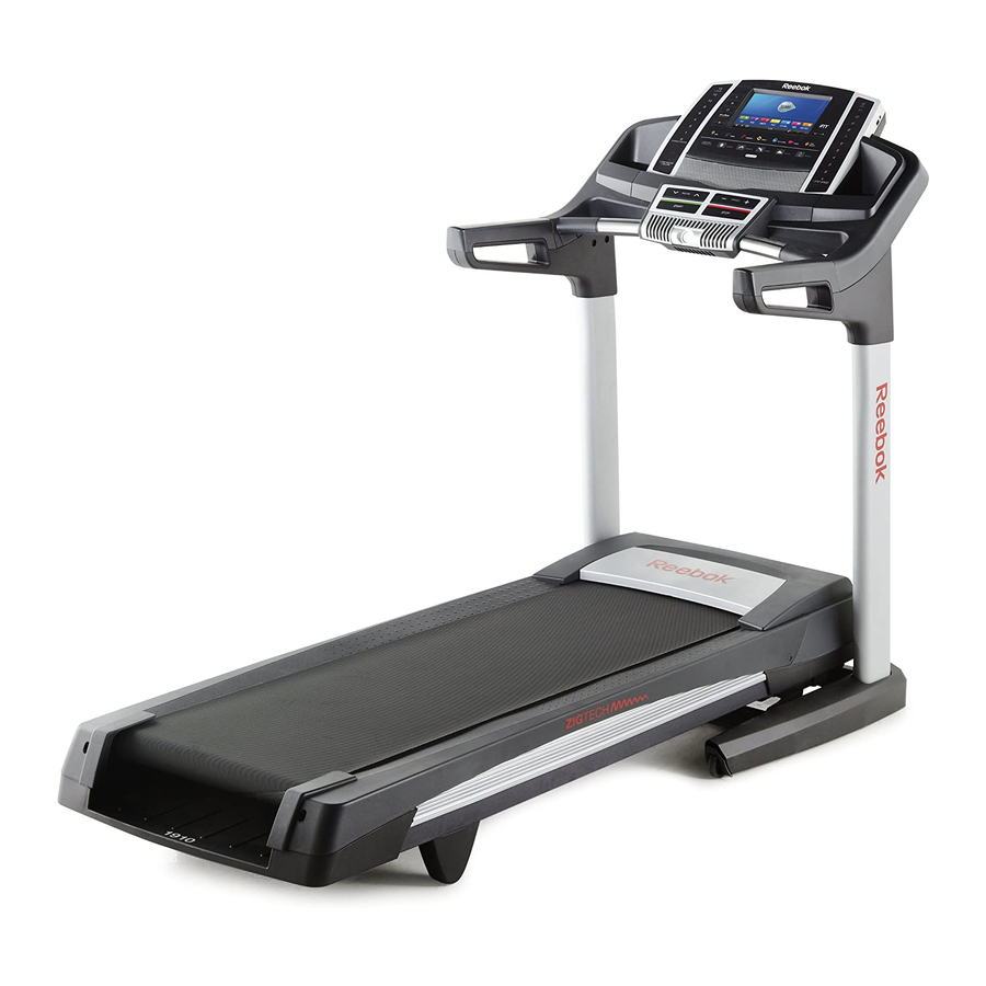
Thank you for selecting the revolutionary reading this manual, please see the front cover of this REEBOK 1910 treadmill. The 1910 treadmill offers an manual. To help us assist you, please note the product ® impressive selection of features designed to make your model number and serial number before contacting us. -
Page 8: Part Identification Chart
PART IDENTIFICATION CHART Use the drawings below to identify small parts used for assembly. The number in parentheses below each draw- ing is the key number of the part, from the PART LIST near the end of this manual. The number following the key number is the quantity used for assembly. -
Page 9: Assembly
ASSEMBLY •• To hire an authorized service technician •• Left parts are marked ““L”” or ““Left”” and right parts to assemble your exercise equipment, call are marked ““R”” or ““Right.”” 1-800-445-2480. •• To identify small parts, see page 8. •• Assembly requires two persons. ••... - Page 10 3. Pull the Upright Wire (76) and the base ground wire (A) through the indicated hole in the Base (92). Attach the base ground wire (A) to the Base (92) with a #8 x 1/2" Ground Screw (10). Make sure that the Grommet (90) is pressed into Square the square hole in the Base (92).
- Page 11 5. Hold the Left Upright (87) against the Base (92). Be careful not to pinch any wires. Insert two 3/8" x 2 3/4" Screws (7) and two 3/8" x 1 1/4" Screws (8) with two 3/8" Star Washers (14) into the Left Upright.
- Page 12 7. Identify the Left Handrail (81), and hold it near the Left Upright (87). Bracket Tie the wire tie in the Left Handrail (81) securely around the end of the Upright Wire (76). Then, pull the other end of the wire tie until the Upright Wire Wire is routed through the Left Handrail.
- Page 13 9. Set the console assembly face down on a soft surface to avoid scratching the console assembly. Remove the eight indicated Screws (C). Next, lift off the Crossbar (104) and the Console Frame (98). Discard the eight Screws. Console Assembly 10.
- Page 14 11. Attach the Console Frame (98) to the Handrails (81, 85) with four 5/16" x 1 1/2" Screws (4) and four 5/16" Star Washers (12). Start all four Screws, and then tighten them. 12. With the help of a second person, hold the con- sole assembly near the Left Handrail (81).
- Page 15 13. Set the console assembly on the Left Handrail (81) and the Right Handrail (85). Be careful not Console to pinch any wires. Insert the excess Upright Assembly Wire (not shown) into the Left Handrail. Attach the console assembly with six #8 x 1/2" Screws (1) and two #8 x 3/4"...
- Page 16 15. Firmly tighten the four 3/8" x 2 3/4" Screws (7). Then, tighten the four 3/8" x 1 1/4" Screws (8) (only one side is shown). Press the Left Base Cover (78) and the Right Base Cover (89) onto the Base (92) until they snap into place.
-
Page 17: The Chest Heart Rate Monitor
THE CHEST HEART RATE MONITOR HOW TO PUT ON THE HEART RATE MONITOR •• Do not expose the heart rate monitor to direct sun- light for extended periods of time; do not expose it The heart rate to temperatures above 122° F (50° C) or below 14° monitor consists of F (-10°... -
Page 18: Operation And Adjustment
OPERATION AND ADJUSTMENT HOW TO CONNECT THE POWER CORD nominal 120-volt circuit capable of carrying 15 or more amps. To avoid overloading the circuit, do Use a Surge Suppressor not plug other electrical devices, except for low- power devices such as cell phone chargers, into Your treadmill, like other electronic equipment, can be the surge suppressor or into an outlet on the same damaged by sudden voltage changes in your home’’s... - Page 19 CONSOLE DIAGRAM MAKE YOUR FITNESS GOALS A REALITY WITH FEATURES OF THE CONSOLE IFIT.COM The advanced treadmill console offers an array of fea- With your new iFit-compatible fitness equipment, you tures designed to make your workouts more effective can use an array of features on iFit.com to make your and enjoyable.
- Page 20 HOW TO TURN ON THE POWER HOW TO USE THE TOUCH SCREEN IMPORTANT: If the treadmill has been exposed to The console features a tablet with a full-color touch cold temperatures, allow it to warm to room tem- screen. The following information will help you become perature before turning on the power.
- Page 21 HOW TO SET UP THE CONSOLE The console is now ready for you to begin working out. The following pages explain the various workouts and Before using the treadmill for the first time, set up the other features that the console offers. console.
- Page 22 HOW TO USE THE MANUAL MODE of the numbered 1 Step Incline/Decline buttons. Each time you press one of the buttons, the incline 1. Insert the key into the console. will gradually change until it reaches the selected incline setting. See HOW TO TURN ON THE POWER on page 20.
- Page 23 If desired, adjust the volume by pressing the Vol 7. Turn on the fan if desired. increase and decrease buttons on the console. The fan features several speed settings and an To pause the workout, touch one of the menu but- auto mode.
- Page 24 HOW TO USE AN ONBOARD WORKOUT If the speed and/or incline settings are too high or too low at any time during the workout, you can 1. Insert the key into the console. override the settings by pressing the Speed or Incline buttons.
- Page 25 HOW TO USE A SET-A-GOAL WORKOUT The workout will function in the same way as the manual mode (see pages 22 and 23). 1. Insert the key into the console. The workout will continue until you reach the goal See HOW TO TURN ON THE POWER on that you set.
- Page 26 HOW TO USE AN IFIT WORKOUT Before some workouts will download, you must add them to your schedule on iFit.com. Note: To use an iFit workout, you must have access to a wireless network (see HOW TO USE THE For more information about the iFit workouts, WIRELESS NETWORK MODE on page 30).
- Page 27 HOW TO USE THE EQUIPMENT SETTINGS MODE IMPORTANT: You must still unplug the power cord after using the treadmill. Set the update 1. Select the settings main menu. time for a time when you normally use the treadmill and will be available to unplug the Insert the key into the console power cord after an update.
- Page 28 11. Enable or disable a passcode. Next, press the play button on your MP3 player, CD player, or other personal audio player. Then, adjust the The console features a child-safety passcode, volume level on your personal audio player or press designed to prevent unauthorized users from using the Vol increase and decrease buttons on the console.
- Page 29 HOW TO USE THE MAINTENANCE MODE Note: Occasionally, a firmware update may cause your console to function slightly differently. These 1. Select the settings main menu. updates are always designed to improve your exer- cise experience. See step 1 on page 27. 4.
- Page 30 HOW TO USE THE WIRELESS NETWORK MODE An information box will ask if you want to connect to the wireless network. Touch the Connect button The console features a wireless network mode that to connect to the network or touch the Cancel but- allows you to set up a wireless network connection.
-
Page 31: How To Fold And Move The Treadmill
HOW TO FOLD AND MOVE THE TREADMILL HOW TO FOLD THE TREADMILL HOW TO MOVE THE TREADMILL To avoid damaging the treadmill, adjust the incline Before moving the treadmill, fold it as described at the to the lowest position before you fold the treadmill. left. -
Page 32: Troubleshooting
TROUBLESHOOTING Most treadmill problems can be solved by following SYMPTOM: The console displays remain lit when the simple steps below. Find the symptom that you remove the key from the console applies, and follow the steps listed. If further assis- tance is needed, see the front cover of this manual. - Page 33 SYMPTOM: The walking belt slows when walked on SYMPTOM: The walking belt is off-center or slips when walked on a. Use only a surge suppressor that meets all of the speci cations described on page 18. a. If the walking belt is off-center, rst remove the key and UNPLUG THE POWER CORD.
-
Page 34: Exercise Guidelines
EXERCISE GUIDELINES Burning Fat——To burn fat effectively, you must exer- WARNING: cise at a low intensity level for a sustained period of Before beginning this time. During the first few minutes of exercise, your or any exercise program, consult your physi- body uses carbohydrate calories for energy. -
Page 35: Part List
PART LIST Model No. RBTL19013.0 R1212A Key No. Qty. Description Key No. Qty. Description #8 x 1/2" Screw Drive Motor Belt #8 x 3/4" Screw Frame 3/8" x 2" Bolt Right Rear Foot 5/16" x 1 1/2" Screw Left Rear Foot 5/16"... -
Page 36: Exploded Drawing
EXPLODED DRAWING A Model No. RBTL19013.0 R1212A... - Page 37 EXPLODED DRAWING B Model No. RBTL19013.0 R1212A...
- Page 38 EXPLODED DRAWING C Model No. RBTL19013.0 R1212A...
- Page 39 EXPLODED DRAWING D Model No. RBTL19013.0 R1212A...
-
Page 40: Ordering Replacement Parts
ORDERING REPLACEMENT PARTS To order replacement parts, please see the front cover of this manual. To help us assist you, be prepared to pro- vide the following information when contacting us: •• the model number and serial number of the product (see the front cover of this manual) ••...
Need help?
Do you have a question about the 1910 Treadmill and is the answer not in the manual?
Questions and answers