Table of Contents
Advertisement
Quick Links
Advertisement
Table of Contents

Related Manuals for Panasonic Lumix DMC-LS5PU


Summary of Contents for Panasonic Lumix DMC-LS5PU
-
Page 1: Digital Camera
ORDER NO. DSC1108045CE Digital Camera DMC-LS5PU Model No. DMC-LS5E DMC-LS5EE DMC-LS5GC DMC-LS5GF DMC-LS5GN DMC-LS5GW Colour (S)...Silver Type (K)...Black Type (P)...Pink Type © Panasonic Corporation 2011 Unauthorized copy- ing and distribution is a violation of law. -
Page 2: Table Of Contents
TABLE OF CONTENTS PAGE PAGE 1 Safety Precautions -----------------------------------------------3 1.1. General Guidelines ----------------------------------------3 1.2. Leakage Current Cold Check ---------------------------3 1.3. Leakage Current Hot Check (See Figure 1.)--------3 1.4. How to Discharge the E.Capacitor on the Frame Unit KIT----------------------------------------------4 2 Warning --------------------------------------------------------------5 2.1. -
Page 3: Safety Precautions
1 Safety Precautions 1.1. General Guidelines 1.3. Leakage Current Hot Check 1. IMPORTANT SAFETY NOTICE (See Figure 1.) There are special components used in this equipment 1. Plug the AC cord directly into the AC outlet. Do not use which are important for safety. These parts are marked by an isolation transformer for this check. -
Page 4: How To Discharge The E.capacitor On The Frame Unit Kit
1.4. How to Discharge the E.Capacitor on the Frame Unit KIT CAUTION: 1. Make sure to discharge the E.capacitor on the Frame Unit KIT. 2. Be careful of the high voltage circuit on the Frame Unit KIT when servicing. [Discharging Procedure] 1. -
Page 5: Warning
2 Warning 2.1. Prevention of Electrostatic Discharge (ESD) to Electrostatically Sensitive (ES) Devices Some semiconductor (solid state) devices can be damaged easily by static electricity. Such components commonly are called Elec- trostatically Sensitive (ES) Devices. The following techniques should be used to help reduce the incidence of component damage caused by electrostatic discharge (ESD). -
Page 6: Service Navigation
3 Service Navigation 3.1. Introduction This service manual contains technical information, which allow service personnel’s to understand and service this model. Please place orders using the parts list and not the drawing reference numbers. If the circuit is changed or modified, the information will be followed by service manual to be controlled with original service manual. 3.2. -
Page 7: How To Define The Model Suffix (Ntsc Or Pal Model)
There are four kinds of DMC-LS5, regardless of the colours. • a) DMC-LS5E • b) DMC-LS5EE • c) DMC-LS5GN • d) DMC-LS5PU/GC/GF/GW What is the difference is that the “INITIAL SETTINGS” data which is stored in Flash-ROM mounted on MAIN P.C.B.. 3.4.1. Defining methods: To define the model suffix to be serviced, refer to the nameplate which is putted on the bottom side of the Unit. -
Page 8: Initial Settings
3.4.2. INITIAL SETTINGS: After replacing the MAIN P.C.B., make sure to perform the initial settings after achieving the adjustment by ordering the following procedure in accordance with model suffix of the unit. 1. PROCEDURES: Step 1. Setup: a. Attach the Battery to the unit. b. - Page 9 d. Input the Serial Number by 12 digits * To make it to 12 digits, put the character of “%” in the head. e. Click the “Set Area S/N”, then “OK” window is displayed. NOTE: If the Initial Setting is executing, the setting item of DSC returns to the state of the shipment. Step 3.Confirmation : a.
-
Page 10: Specifications
4 Specifications... -
Page 11: Location Of Controls And Components
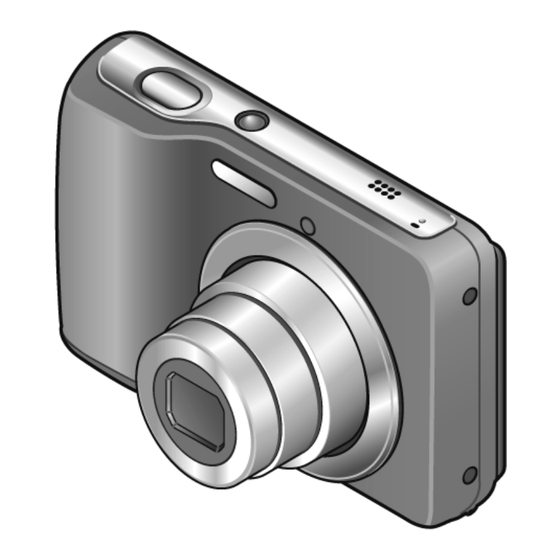
5 Location of Controls and Components Shutter button Tripod receptacle Ensure that the tripod is Power button stable. Self-timer indicator Speaker Microphone Lens barrel Card/Battery door Lens Flash Zoom button Hand strap eyelet We recommend using the supplied hand strap to avoid dropping the camera. -
Page 12: Taking Pictures With Your Own Settings
Taking pictures with your own settings [Normal Picture] Mode Recording Mode: Using the [Rec] menu to change settings and set up your own recording environment. Display the screen for Recording Shutter button Mode selection Select [Normal Picture] Mode Take a picture Press halfway Press fully (press lightly to... -
Page 13: Service Fixture & Tools
6 Service Fixture & Tools 6.1. Service Fixture and Tools The following Service Fixture and tools are used for checking and servicing this unit. REMARKS 1. ABOUT “LIGHT BOX”:... -
Page 14: Disassembly And Assembly Instructions
7 Disassembly and Assembly Instructions 7.1. Disassembly Flow Chart This is a disassembling chart. When installing, perform this chart conversely. 7.2. PCB Location... -
Page 15: Disassembly Procedure
7.3. Disassembly Procedure 7.3.1. Removal of the Front Case Unit Item Removal Front Case Unit (Fig. D1) Card Battery 3 Screws (A) 2 Screws (B) (Fig. D2) 6 Locking tabs Front Case Unit Rear Case Unit (Fig. D3) Jack Door AF Panel Light 1 Screw (C) 1 Screw (D) - Page 16 7.3.2. Removal of the Rear Case Unit (Fig. D3) (Fig. D4)
- Page 17 7.3.3. Removal of the Top Case Unit (Fig. D5) (Fig. D6)
- Page 18 7.3.4. Removal of the LCD Unit (Fig. D8) (Fig. D7)
- Page 19 7.3.5. Removal of the Main P.C.B. and Lens Unit (W/CCD) (Fig. D10) (Fig. D9)
- Page 20 7.3.6. Removal of the Lens Unit (W/CCD) 7.3.7. Removal of the Battery Door Unit NOTE: When Disassembling and Installing for the Lens Unit (W/CCD) 1. Take care that the dust and dirt are not entered into the lens. In case of the dust is putted on the lens, blow off them by airbrush.
-
Page 21: Measurements And Adjustments
8 Measurements and Adjustments 8.1. Introduction When servicing this unit, make sure to perform the adjustments necessary based on the part(s) replaced. To perform the adjustment, it is necessary to use the “PDCE570C.elf”, “cal.txt” and “LENSSN.TXT” software. The Adjustment software “PDCE570C.elf”, “cal.txt” and “LENSSN.TXT” together with its installation instruction are available at “TSN Website”. -
Page 22: Adjustment Procedures
8.3. Adjustment procedures 8.3.1. Read Lens Barcode 1. Preparation of the SD CARD a. Format the SD card. b. Put PDCE570C.elf, cal.txt, LENSSN.TXT into the SD card on root directory. c. Make sure that the content text of cal.txt is “PDCE570a cal menu”. d. - Page 23 8.3.2. WB Calibration 1. Preparation of the SD CARD a. Format the SD card. b. Put PDCE570C.elf, cal.txt into the SD card on root directory. c. Make sure that the content text of cal.txt is “PDCE570a cal menu”. 2. Setting the DSC for calibration a.
- Page 24 8.3.3. CCD Calibration 1. Preparation of the SD CARD a. Format the SD card. b. Put PDCE570C.elf, cal.txt into the SD card on root directory. c. Make sure that the content text of cal.txt is “PDCE570a cal menu”. 2. Setting the DSC for calibration a.
-
Page 25: Lens Calibration
8.3.4. LENS Calibration 1. Preparation of the SD CARD a. Format the SD card. b. Put PDCE570C.elf, cal.txt into the SD card on root directory. c. Make sure that the content text of cal.txt is “PDCE570a cal menu”. 2. Setting the DSC for calibration a. - Page 26 8.3.5. Blemish Calibration 1. Preparation of the SD CARD a. Format the SD card. b. Put PDCE570C.elf, cal.txt into the SD card on root directory. c. Make sure that the content text of cal.txt is “PDCE570a cal menu”. 2. Setting the DSC for calibration a.
- Page 27 8.3.6. Result Calibration 1. Preparation of the SD CARD a. Format the SD card. b. Put PDCE570C.elf, cal.txt into the SD card on root directory. c. Make sure that the content text of cal.txt is “PDCE570a cal menu”. 2. Setting the DSC for calibration a.
-
Page 28: Maintenance
9 Maintenance 9.1. Cleaning Lens and LCD Panel Do not touch the surface of lens and LCD Panel with your hand. When cleaning the lens, use air-Blower to blow off the dust. When cleaning the LCD Panel, dampen the lens cleaning paper with lens cleaner, and the gently wipe the its surface. Note: The Lens Cleaning KIT ;... -
Page 29: Interconnection Diagram
10 Interconnection Diagram TOP P.C.B. (COMPONENT SIDE) BATTERY SPEAKER MICROPHONE LCD UNIT UNIT LENS UNIT MAIN P.C.B. (COMPONENT SIDE) : (FOIL SIDE) DMC-LS5 INTERCONNECTION DIAGRAM... - Page 30 Model No. : DMC-LS5 series parts list notice S1/5 ページ...
- Page 31 Model No. : DMC-LS5 series Frame and Casing Section S2/5 ページ...
- Page 32 Model No. : DMC-LS5 series Packing Parts and Accessories S3/5 ページ...
- Page 33 Model No. : DMC-LS5 series Parts List Ref. Safety Part No. Part Name & Description Q'ty Remarks VU9PN840000 FRONT CASE UNIT 1 (-S) VU9PN840002 FRONT CASE UNIT 1 (-K) VU9PN840004 FRONT CASE UNIT 1 (-P) VU9PN840006 REAR CASE UNIT 1 (-S) VU9PN840006 REAR CASE UNIT 1 (-K)
- Page 34 Model No. : DMC-LS5 series Parts List Ref. Safety Part No. Part Name & Description Q'ty Remarks VPK5109 PACKING CASE 1 (-S)PU/E/EE/GC/GN VPK5111 PACKING CASE 1 (-K)PU/E/EE/GC/GN VPK5113 PACKING CASE 1 (-P)PU/E/EE/GC/GN VPK5110 PACKING CASE 1 (-S)GF/GW VPK5112 PACKING CASE 1 (-K)GF/GW VPK5114 PACKING CASE...
Need help?
Do you have a question about the Lumix DMC-LS5PU and is the answer not in the manual?
Questions and answers