Table of Contents
Advertisement
Signal Processors 18-0121-B
C
O N T E N T S
R
S
T A
E R I E S
8 3 4 / 8 3 5
S E R I E S
S
8 4 4
E R I E S
S
8 6 6
E R I E S
6/8/99
10:24 AM
I I . . . . . . . . . . . . . . . . . . . . . 2
I I. . . . . . . . . . . . . . . .. . 11
I I . . . . . . . . . . . . . . . . . . . .. . 17
I I . . . . . . . . . . . . . . . . . . . . . .20
Page 1
1
Advertisement
Table of Contents

Subscribe to Our Youtube Channel
Summary of Contents for DOD RTA Signal Processors
- Page 1 Signal Processors 18-0121-B 6/8/99 10:24 AM Page 1 O N T E N T S E R I E S I I ..... 2 8 3 4 / 8 3 5 S E R I E S I I.
- Page 2 Signal Processors 18-0121-B 6/8/99 10:24 AM Page 2 C A U T I O N R I S K O F E L E C T R I C S H O C K D O N O T O P E N A T T E N T I O N : R I S Q U E D E C H O C E L E C T R I Q U E - N E P A S O U V R I R W A R N I N G :...
- Page 3 Signal Processors 18-0121-B 6/8/99 10:24 AM Page 3 These units comply with the European “EMC Directive” for emissions and suscept- ability The power cord is terminated in a CEE7/7 plug (Continental Europe). The green/yellow wire is connected directly to the unit's chassis. If you need to change the plug, and if you are qualified to do so, refer to the table below.
- Page 4 “window” RTAs. ABOUT THE DOD RTA The DOD Electronics RTA Series II is a window-type RTA. It covers the audi- ble frequency spectrum (20 Hz to 20 kHz), and has a five LED level meter for each of the 31 audio frequency bands that it covers.
- Page 5 10:24 AM Page 5 The DOD RTA Series II also has its own internal pink noise generator and level control. Pink noise is defined as an audio signal that contains all frequencies at equal energy levels. For this reason, pink noise sounds a lot like static.
- Page 6 Since the RTA measures in 1/3rd octave increments, it is easiest to use a 1/3rd octave graphic equalizer in the system, such as DOD's 231 Series II, 431 Series II, or 831 Series II.
- Page 7 Signal Processors 18-0121-B 6/8/99 10:24 AM Page 7 characteristics vary greatly as you move around the room (particularly with multiple driver systems). If you find that different areas of the room behave differently, try to average the settings on the equalizer to correct the room as a whole.
- Page 8 Signal Processors 18-0121-B 6/8/99 10:24 AM Page 8 several positions in the room and compromise the equalization/attenuation setting for the best possible sound. This may be done either with the equal- izer or by aiming the tweeters of the main speakers differently. Low frequency dips and peaks are room-related, and may be corrected to some extent.
- Page 9 Signal Processors 18-0121-B 6/8/99 10:24 AM Page 9 Another method for equalizing a monitor system uses the stage microphones without the RTA’s calibrated microphone. Most reinforcement type microphones are not flat in their frequency response. This procedure, however, takes the stage microphone’s response into account as you equalize the system.
- Page 10 Signal Processors 18-0121-B 6/8/99 10:24 AM Page 10 PECIFICATIONS Number of Frequency Bands: 31. Display Range: 1 dB step per LED, or 3 dB step per LED. Level Range: 53 dB to 107 dB SPL. Display Attack Time: Peak, Instantaneous. Frequency Accuracy: ±4%.
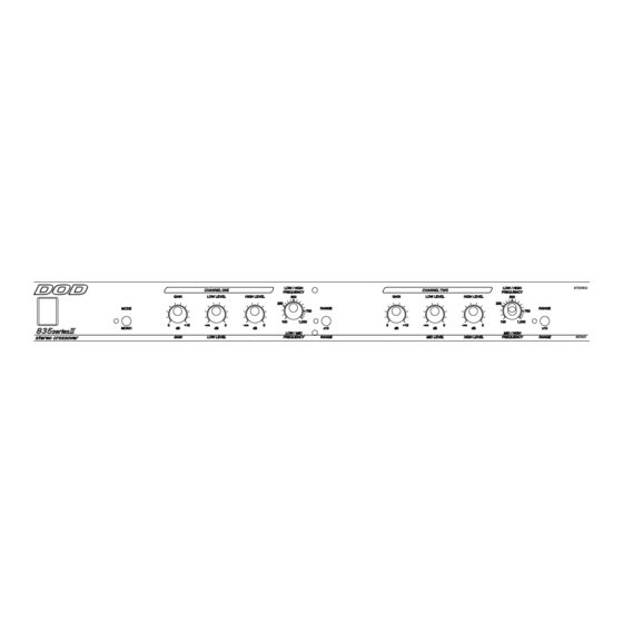
- Page 11 RANGE MONO NTRODUCTION The DOD 834 Series II is a stereo 3-way, mono 4-way crossover, and the 835 Series II is a stereo 2-way, mono 3-way crossover. These high-quality crossover networks are designed to extract maximum sound quality from your multi-amped sound system at a price working musicians can afford.
- Page 12 Signal Processors 18-0121-B 6/8/99 10:24 AM Page 12 power amplifiers to be much smaller, yet adequate to handle the demands of the high frequency content of the program material. Since each element of the system is driven by its own amplifier, any distortion that occurs is limited to the frequencies of the overdriving power amplifier.
- Page 13 Signal Processors 18-0121-B 6/8/99 10:24 AM Page 13 FOR UNBALANCED AMPLIFIER CONNECTION: To make an unbalanced connection to the unit's XLR connectors, wire the line connectors as follows: Pin 2: high Pin 3: NO CONNECTION Pin 1: ground Use tip-sleeve 1/4" phone plug connectors for connection to the amplifiers, wired as follows: tip: high sleeve: ground...
- Page 14 Signal Processors 18-0121-B 6/8/99 10:25 AM Page 14 • 834: Set the LOW/MID crossover frequency for each channel according to the front panel markings. 835: Set the LOW/HIGH crossover frequency for each channel accord- ing to the front panel markings. •...
- Page 15 Signal Processors 18-0121-B 6/8/99 10:25 AM Page 15 and drivers. STEREO OPERATION USING A MONO SUBWOOFER This mode of operation provides: 834: Channel 1 and Channel 2 high frequency outputs, Channel 1 and Channel 2 mid frequency outputs, and one summed low frequency output.
- Page 16 Signal Processors 18-0121-B 6/8/99 10:25 AM Page 16 Crossover Frequencies - Stereo: LOW/MID: 50 Hz to 5 kHz in two ranges, MID/HIGH: 750 Hz to 7.5 kHz. - Mono: LOW/LOW-MID: 50 Hz to 5 kHz in two ranges, LOW-MID/HIGH-MID: 50 Hz to 5 kHz in two ranges, HIGH-MID/HIGH: 2 kHz to 20 kHz.
- Page 17 NTRODUCTION The DOD 844 Series II Quad Noise Gate consists of 4 independent noise gates in a single rack space unit. Threshold, release time, and attenuation (0 dB to 90 dB) for each gate are user controllable. Special features include a Key input for gating, or "keying", from a signal other than the input.
- Page 18 Signal Processors 18-0121-B 6/8/99 10:25 AM Page 18 PPLICATIONS The 844 Series II Quad Noise Gate can be used in a variety of situations. The most typical use is a standard noise gate. With the Key Source switch set to INT and the Attenuation control set to 90 dB, the unit will attenuate the input signal when its level falls below the threshold level.
- Page 19 Signal Processors 18-0121-B 6/8/99 10:25 AM Page 19 • Switch the Key Source control to Ext. The detector will now ignore the high frequency signals (in this case, the cymbals), and will allow the drum sig- nal though only when the drum is struck. Keying can be used for more than simply removing noise.
- Page 20 REDUCTION NTRODUCTION The DOD 866 Series II is a stereo gated compressor/limiter that can be oper- ated as two independent compressor / limiters or as a single stereo unit. The 866 Series II incorporates "soft knee" characteristics in its compression action to yield natural sound under gain reduction conditions.
- Page 21 Signal Processors 18-0121-B 6/8/99 10:25 AM Page 21 will light whenever the signal is being gated. To disable the gating action, set the Gate Threshold control to the full counter-clockwise position (the gate control is fully independent of all other controls on the 866). Input Gain: The Input Gain control allows you to adjust the signal level to the compressor.
- Page 22 Signal Processors 18-0121-B 6/8/99 10:25 AM Page 22 Stereo Link: Depressing the Stereo Link switch links the two compressor channels for stereo operation. In stereo mode, the compressor will react to either channel, while reducing gain in both channels. Both channels of the 866 are identical in control and function EXCEPT when placed in the stereo mode.
- Page 23 Signal Processors 18-0121-B 6/8/99 10:25 AM Page 23 The Compressor Threshold controls the point above which the compressor begins to reduce the gain. For compression, the Compressor Threshold is set low, so that even low level signal will activate the compression. For limiting, the Compressor Threshold is set high so that all of the dynamics of the signal are preserved, but extremely high levels are reduced to protect amplifiers, speakers, or to prevent tape saturation.
- Page 24 For this rea- son DOD has incorporated a noise gate in the 866. A gate acts like a com- pressor in reverse. When a signal crosses the gate threshold, it is allowed to pass unaffected.
- Page 25 To prevent shifting, DOD has incorporated a Stereo Link switch on the 866. This switch allows both channels to track in perfect uni- son while the detectors for each channel operate independently.
- Page 26 Signal Processors 18-0121-B 6/8/99 10:25 AM Page 26 in that frequency range, thus reducing the sibilance of the program material. Attack and Release times should be set fairly short, and the compression ratio should be below 8:1. PECIFICATIONS Frequency Response: 10 Hz - 30 kHz, ±0.5 dB. THD+Noise: 0.06%.
- Page 27 Signal Processors 18-0121-B 6/8/99 10:25 AM Page 27 A Harman International Company...
- Page 28 LECTRONICS ORPORATION 8760 S OUTH ANDY ARKWAY 84070 ANDY NTERNATIONAL ISTRIBUTION VERLOOK 03031 MHERST AMPSHIRE U.S.A FAX (603) 672-4246 IS A EGISTERED RADEMARK OF DOD E LECTRONICS © 1994 DOD E LECTRONICS ORPORATION U.S.A. 2/94 RINTED U.S.A. ANUFACTURED DOD 18-0121-B...
Need help?
Do you have a question about the RTA Signal Processors and is the answer not in the manual?
Questions and answers