Table of Contents
Advertisement
Quick Links
Advertisement
Table of Contents

Related Manuals for IOGear MiniView ULTRA GCS138


Summary of Contents for IOGear MiniView ULTRA GCS138
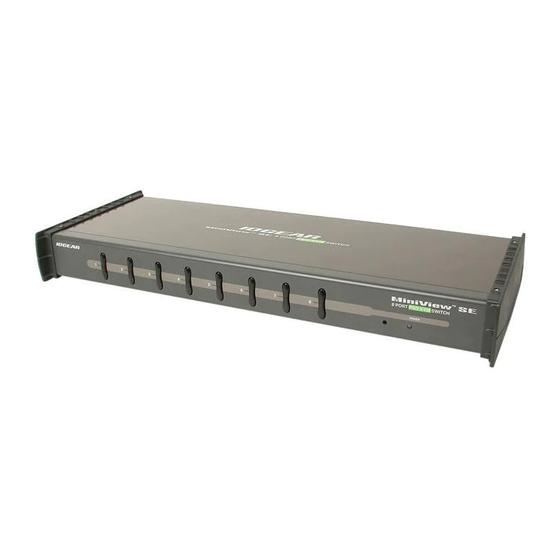
- Page 1 MiniView™ UL TRA 8 Port KVM Switch (GCS138 Installation Manual)
- Page 2 Microsoft and Windows are registered trademarks of Microsoft Corporation. IBM is a registered trademark of International Business Machines, Inc. Macintosh, G3/G4 and iMac are registered trademarks of Apple Computer, Inc. IOGEAR makes no warranty of any kind with regards to the information presented in this document.
- Page 3 Thank you for purchasing one of the most feature-rich KVM switches on the market. IOGEAR’s KVM switches are first-rate connectivity accessories designed to help reduce the frustration of managing multiple computer systems. With the MiniView™ ULTRA series by IOGEAR, you can access multiple computers from a single console(keyboard, mouse and monitor).
-
Page 5: Table Of Contents
Table of Contents Table of Contents: Package Contents Overview Features Requirements Introduction Installation On-Screen-Display (OSD) Operation Power Off Port ID Numbering Port Selection Function Keys Appendix (Troubleshooting) Specification Radio & TV Interference Statement Limited Warranty... -
Page 6: Package Contents
Package Contents This package contains: 1 MiniView™ ULTRA KVM switch (GCS138) 1 User Manual 1 Registration Card 1 Power Adapter 1 Quick Start Guide If any items are damaged or missing please contact your dealer. -
Page 7: Overview
Overview Overview The MiniView™ ULTRA GCS138 KVM (Keyboard, Video, Mouse) Switch is a control unity that allows access to eight computers from a single console (keyboard, mouse and monitor). Before the development of the MiniView™ ULTRA, the only way to control multiple computer configurations from a single console was through a complex and costly network system. -
Page 8: Features
Features Features - Cascadable To Three Levels - Control Up to 512 PCs From a Single Console - No Software Required - PC Selection Via Front Panel Switches, HotKeys, or OSD (On Screen Display) - Quick View Scan Feature for Monitoring Selected PCs - PS/2 and Serial Mouse Emulation Provided For System Bootup - Console’s PS/2 Mouse Controls All Connnected PCs - Even Those With Serial Mice - PS/2 Compatible Mouse Support - Microsoft Intellimouse Pro, Logitech FirstMouse Support*... -
Page 9: Requirements
Requirements Requirements Console - A VGA, SVGA, or Multisync monitor capable of the highest resolution that you will be using on any PC in the installation - A PS/2 Style Mouse - A PS/2 Style Keyboard The following equipment must be installed or on board each PC that is to be connected to the system: - A VGA, SVGA or Multisync card. - Page 10 2. If your PC uses standard 9 pin serial port for the mouse, you will need to purchase a PS/2-to-Serial mouse adapter (Part No.2A-105; a standard mouse adapter will probably not work). In order to plug the cable into the computer’s serial port. 3. Because of the wiring and pin assignments, you cannot use a Serial-to-PS/2 adapter at the end that plugs into the GCS138.
-
Page 11: Introduction
Introduction on MiniView ULTRA The MiniView ULTRA GCS138 is a KVM switch that controls access to multiple computers from a single console (keyboard, monitor, and mouse). Before the development of the MiniView ULTRA, the only way to control multiple computer configura- tions from a single console was through a complex and costly network system. - Page 12 Introduction Front View 1, 2 1. Port LEDs On Line: Lights BLUE to indicate that the PC attached to the corresponding port is up and running. If the LED is flashing, it indicates that the Port is being used for Cascading to another MiniView ULTRA switch.
- Page 13 Introduction 3. MiniView ULTRA Reset To reset the MiniView ULTRA, use a thin object (such as the end of a paper clip, or a ballpoint pen), to press this recessed switch in to initiate a warm reset. If the switch is kept in for longer than three seconds, a cold reset takes place. 4.
- Page 14 Introduction Back View 1. Power Jack The power adapter plugs in here. 2. Console Port Section If this is a first station unit. Your monitor, keyboard and mouse plug in here. If this is a daisy chained unit. The cables that link back to a port on a higher MiniView ULTRA unit plug in here.
- Page 15 Introduction...
-
Page 16: Installation
Installation Setup and Installation (Power Adapter) Step. 1 (Power Adapter Connection) * Before you begin, please make sure that the power to all devices has been turned off. Connecting your console to the MiniView ULTRA. You will need your VGA monitor, PS/2 mouse, PS/2 keyboard and the MiniView ULTRA power adapter. - Page 17 Installation Setup and Installation (Console Port Connection on KVM Switch) Step. 2 (Console Connection) 1. Connect the end of your monitor cable into the console side of the MiniView ULTRA video port. 2. Plug in your PS/2 mouse and PS/2 keyboard into their designated ports on the console side of the MiniView ULTRA.
- Page 18 Setup and Installation (CPU Port Connection on KVM Switch) Step. 3 (CPU Port Connection) 1. Connect the female end of your IOGEAR video cable into the male video port on the MiniView ULTRA labeled with a CPU port number. 2. Plug in the PS/2 mouse and PS/2 keyboard connectors located on the same end as the female video connector. The...
- Page 19 Installation Setup and Installation (Port Connections on back of Computer) Step. 4 (Connecting the PCs) 3. Plug in the remaining PS/2 mouse and PS/2 keyboard connectors into your PC’s keyboard and mouse ports. 4. Repeat steps 1-3 for any additional computers you wish to connect to the MiniView ULTRA.
- Page 20 (Cascading MiniView Ultra Units) * Use standard IOGEAR PS/2 cables to cascade units. 1. Connect the female end of your IOGEAR video cable into the male video port on an available CPU section of the MiniView ULTRA. 2. Plug in the PS/2 keyboard connectors located on the same end as the female video connector. The cables have images...
- Page 21 Installation Setup and Installation (Cascading MiniView ULTRA) Step. 6 (Cascading Cont.) 3. Now plug the male end of the video cable into the female video port on the secondary MiniView ULTRA console section. 4. Plug in the remaining PS/2 mouse and PS/2 keyboard connectors into the keyboard and mouse ports on the secondary MiniView ULTRA console section.
- Page 22 Cascading in pyramid format (Cascading Diagram) Step. 7 (Cascading In Pyramid format) - Red connection indicate level 1 (8 computers) - Green connection indicate level 2 (64 computers) - Orange connection indicate level 3 (512 computers)
-
Page 23: On-Screen-Display (Osd) Operation
Switching still works, using OSD is a great deal more convenient - especially in large, daisy chained installations where a great number of PCs are connected to a several MiniView ULTRA GCS138 units, and it is difficult to keep track of which port a particular PC is attached to. -
Page 24: Osd Main Menu Headings
OSD Operation OSD Main Menu Headings: This column lists the Port ID numbers (Station Number - Port Number) for all the CPU Ports on the installation. The simplest method to access a particular PC (assuming you know which port it is attached to), is to use the Navigation keys to move the Highlight Bar to the desired location, then pres [Enter]. -
Page 25: Hotkey Navigation
OSD Operation HotKey Navigation: HotKey navigation can be used under OSD mode. To do this: 1. Activate the OSD by pressing the Ctrl key twice ([Ctrl] [Ctrl]). 2. From the Main Menu, you can go directly to any port by keying in [Ctrl+Alt+Shift], then the Port ID Nubmer, and then pressing [Enter]. - Page 26 OSD Operation Access authorization OSD Operation In order to prevent unauthorized access to the computers, the OSD provides a password security feature. If a password has been set, the OSD will request that the user specify it before allowing entry. Setting a password: 1.
-
Page 27: Power Off
• If the unit is operating under external power, unplug the power adapter cable. 2. Wait 10 seconds, then power on the MiniView ULTRA GCS138 stations back in, starting with the last station in the chain and working back to the station you originally shut down. -
Page 28: Hot Plugging
Hot Plugging: The MiniView GCS138 supports hot plugging, which means that components can be removed and added back into the installation by unplugging their cables from the CPU ports without shutting the unit down. There are certain procedures that must be followed in order for hot plugging to work properly: - Hot Plugging CPU Ports: 1. -
Page 29: Port Id Numbering
Port ID Numbering Since each CPU Port on a MiniView installation is assigned a unique Port ID, you can directly access any computer on any level. Specify the Port ID using the Hotkey port selection method or the OSD Main Menu. The Port ID is a one, two, or three digit number that is determined by the Stage Level and CPU Port number of the MiniView unit that the computer is connected to. -
Page 30: Port Selection
Controlling all the PCs connected up in your MiniView ULTRA GCS138 installation from a single console could not be easier. Four methods are available that provide instant access to any PC on the chain: Manual, Quick View Scanning, Hotkey, and... - Page 31 Port Selection - Manual Simply press the appropriate port selection switch on the MiniView ULTRA front panel. After you press the switch, the selected LED lights to indicate that the port is currently selected. The On Screen Display automatically switches to highlight the PC that you have selected. NOTE: On a daisy chained installation, you must press the Port Selection switch on the MiniView ULTRA station that connects directly to the PC you want to access.
-
Page 32: Function Keys
Function Keys Function Keys: Pressing a Function Key brings up a related submenu that is used to configure and control the OSD to make it convenient for you to work with. For example, you can: rapidly switch to any port; scan selected ports only; limit the list you wish to view;... - Page 33 Function Keys NOTE: (1) If the scanning stops on an empty port, or one where the computer is attached but is powered off, the monitor screen will be blank,and the mouse and keyboard will have no effect. To recover, key in the HotKey sequence (see HotKey Selection , above) for any Port ID that has an active PC attached.
- Page 34 Function Keys NOTE: (1) You can access any port on any list by using the Navigation Keys or Mouse to move the Highlight Bar to it, then pressing [Enter]. (2) If you select a port that does not have a PC attached to it,or if the attached PC is powered Off, the OSD will still switch to it, and will not show an error.
- Page 35 Function Keys F5 Edit: For convenience in remembering which PC is attached to a particular port, every port can be named. The Edit function allows you to name the currently highlighted CPU Port (if it doesn’t already have a name), or to modify/delete the Port Name if it does.
- Page 36 Function Keys F6 Set: When you press [F6] an OSD configuration submenu opens. To change a setting, move the highlight bar to the choice you want, then press [Enter]. On the submenu that appears next, move the highlight bar to the choice you want and press [Enter]. An icon of a pointing finger indicates which choice is the currently selected one.
- Page 37 Function Keys Setti ng Functi on Restore Default Values Clear all settings from memory, and returns the unit to the fact ory defaults. you are asked to conf irm before the procedure goes on. Key in Y, then press [Enter] to compfirm. While the settings are being cleared, a message a appears on the display to indicate so.
- Page 38 PC Connection Table MiniView™ ULTRA: PC Connection Table The following table indicates the relationship between the number of MiniView™ ULTRA units and the number of PCs that they control: 00-08 92-99 183-190 274-281 365-372 08-15 99-106 190-197 281-288 372-379 15-22 106-113 197-204 288-295...
-
Page 39: Appendix (Troubleshooting)
Appendix Troubleshooting (Model: GCS138) Note: If the unit appears to be operating erratically, check all cables for damage and to be sure that they are properly connected. If you are operating under nonpowered mode, use the external power adapter. Symptom... - Page 40 Appendix Symptom Possible Cause Acti on Turn of all MiniView ULTRA units and wait five seconds before turning them back on. Note: If the unit is operating under Bus Power (without I mproper MiniView ULTRA reset. the optional Power Adapter), you must unplug the power cords of any PCs that are connected to it that have the Keyboard 'Power On' function, otherwise the swit ch will still receive power from the PC.
-
Page 41: Specification
Specification Product Specification (MODEL: GCS138) Functi on Specificati on DC 9V, 1.08W (max.) Power Consumption Computer Connections Up to 8 PS/2 enabled comput ers / Up to 512 daisy chained Port Selecti on Pushbutton Switches, HotKeys, OSD Keyboard Ports 9 PS/2 Keyboard Ports (8 computer, 1 console) - Page 42 Specification Functi on Specificati on 3, 5, 10, 15, 20, 30, 40, 60 secs. Scan Interval (OSD Select) Resolution 1920 x 1440 DDC, DDC2, DDC2B Operati ng Temperature 5 ~ 40° C -20 ~ 60° C Storage Temperature Humidity 0 ~ 80% RH, Noncondensing Housi ng Metal Weight...
-
Page 43: Radio & Tv Interference Statement
Radio & TV Interference Statement Radio & TV Interference Statement WARNING!!! This equipment generates, uses and can radiate radio frequency energy and, if not installed and used in accordance with the instruction manual, may cause interference to radio communications. This equipment has been tested and found to comply with the limits for a Class B computing device pursuant to Subpart J of Part 15 of FCC Rules, which are designed to provide reasonable protection against such interference when operated in a commercial environment. -
Page 44: Limited Warranty
Limited Warranty Limited Warranty IN NO EVENT SHALL THE DIRECT VENDOR’S LIABILITY FOR DIRECT, INDIRECT, SPECIAL, INCIDEN- TAL OR CONSEQUENTIAL DAMAGES RESULTING FROM THE USE OF THE PRODUCT, DIST ORITS DOCUMENTATION EXCEED THE PRICE PAID FOR THE PRODUCT. The direct vendor makes no warranty or representation, expressed, implied, or statutory with respect to the contents or use of this documentation, and especially disclaims its quality, performance, merchantability, or fitness for any particular purpose. - Page 46 Contact info. 23 Hubble Drive • Irvine, CA 92618 • (P) 949.428.1111 • (F) 949.428.1100 • www.iogear.com...
Need help?
Do you have a question about the MiniView ULTRA GCS138 and is the answer not in the manual?
Questions and answers