Table of Contents
Advertisement
Advertisement
Table of Contents

Related Manuals for Garmin Fishfinder 250


Summary of Contents for Garmin Fishfinder 250
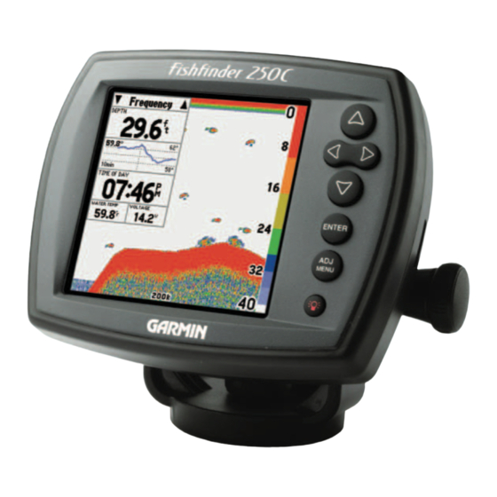
- Page 1 Fishfi nder 250/250C high-resolution sonar owner’s manual (Fishfi nder 250C shown)
- Page 2 Information in this manual is subject to change without notice. Garmin reserves the right to change or improve its products and to make changes in the con- tent without obligation to notify any person or organization of such changes.
-
Page 3: Introduction
Operations for the Fishfi nder 250 and Fishfi nder 250C are the same unless othewise noted. To ensure that you get the most from the Fishfi nder 250/250C, please take the time to read this Owner’ s Manual and learn the operation of your new unit. This manual is broken down into three sections. Section One covers the installation and testing for the Fishfi... -
Page 4: Limited Warranty
Garmin retains the exclusive right to repair or replace the unit or software or offer a full refund of the purchase price at its sole discretion. SUCH REMEDY SHALL BE YOUR SOLE AND EXCLUSIVE REMEDY FOR ANY BREACH OF WARRANTY. -
Page 5: Software License Agreement
TIONS OF THE FOLLOWING SOFTWARE LICENSE AGREEMENT. PLEASE READ THIS AGREEMENT CAREFULLY. Garmin grants you a limited license to use the software embedded in this device (the “Software”) in binary executable form in the normal operation of the product. Title, ownership rights and intellectual property rights in and to the Software remain in Garmin. -
Page 6: Packing List
Garmin dealer immediately. Fishfi nder 250 Standard Package (010-00343-00 w/o transducer): • Fishfi nder 250 Unit • Swivel Mount Bracket and Knobs • Power/Data Cable • Owner’ s Manual • Self-Adhesive Quick Reference Guide • Protective Cover • Flush-Mount Hardware Kit Fishfi... -
Page 7: Selecting A Transducer
Included in the Optional Packages (p. iv) are transom mount transducers and separate speed sensors. These transducers provide good all-around performance. In addition, a variety of optional transducers are available from your local dealer or direct from Garmin. • 200/50kHz, 12/45°, plastic, transom mount, depth, temp •... -
Page 8: Table Of Contents
Introduction Table of Contents Introduction ......i-vi Preface and Registration ....i Warranty . -
Page 9: Section One: Installation
Installing the Fishfi nder 250/250C The Fishfi nder 250/250C must be properly installed according to the following instructions to get the best possible performance. To complete the installation, you’ll need the appropriate fasteners and tools. Verify that all cables can reach the unit mounting location and also take time to read through these instruc- tions prior to installation. - Page 10 Mounting Bracket. To swivel mount the Fishfi nder 250/250C display: Tools (not included) — Drill, Screwdriver (Phillips or Standard), three #8 (4mm) pan head machine bolts with matching nuts and washers and a 5/32” (5mm) drill bit, OR three #8 pan head self-tapping screws and an appropriately-sized drill bit for drilling starter holes.
-
Page 11: Unit Installation
Installing the Unit on the Mounting Bracket 1. Align the slot on the back of the unit with the long mounting knob and slide in place. It may be neces- sary to adjust the long mounting knob to spread the bracket arms apart. (Turn counter-clockwise to widen the bracket arms, clockwise to tighten.) 2. - Page 12 Flush Mounting the Fishfi nder 250/250C Unit The Fishfi nder 250/250C can be fl ush mounted on a fl at panel. When fl ush mounting the Fishfi nder 250/250C, be sure to choose an appropriately sized location for the unit. Check that all cables reach the unit mounting location before beginning installation.
-
Page 13: Connecting The Power/Data Cable
3. Connect the Brown (Data In) wire from the Fishfi nder to the Data OUT wire on the GPS/NMEA harness. 4. Set the Fishfi nder 250/250C NMEA Input/Output to ‘On’ (pg. 20). For Garmin GPS units, set the communications interface to NMEA/NMEA, NMEA In/NMEA Out or NMEA. - Page 14 Output — SDDBT, SDDPT, SDMTW, SDVHW, SDWPL* (only if a waypoint is “marked” in Pointer Mode) *Garmin GPS units will accept the SDWPL (WPL) NMEA sentence and create a waypoint (saved location) at that position (see pg. 15). For compatibility with other brands of GPS or NMEA capable navigation devices, check with that manufacturer to see if their unit accepts/stores NMEA 0183 SDWPL sentences/waypoints.
-
Page 15: Mounting The Transducer
Proper transducer installation is key to getting the best performance from your new unit. If the trans- ducer lead is too short, extension cables are available from your Garmin dealer. Coil and secure any excess cable. DO NOT cut the transducer lead or any part of the transducer cable, as this will void your warranty. -
Page 16: Shoot-Thru-Hull Installation
Installation Mounting the Transducer Weight transducer PVC Pipe to hold it in place or a Can Fill Pipe or Can with water or a Strip Caulk light mineral oil or RTV Sealer Hull Surface Testing the Location Shoot-Thru-Hull Installation To avoid drilling a hole to mount a thru-hull transducer, a transducer may be secured with epoxy inside a boat (“shoot-thru-hull”... -
Page 17: Testing The Installation
Press the POWER/BACKLIGHT key (see pg. 10) and the Fishfi nder 250/250C should power on. If the unit fails to power on, verify that the wiring adapter is seated properly in the back of the unit, the Red and Black wires are connected to the correct polarity, and that the 2-Amp fuse is installed and not blown. -
Page 18: Using The Keypad
Unit Operation Keypad Usage MENU NOTE: Always press and release a key to perform its primary function. Pressing and holding a key will activate its secondary function (if available). Using the Keypad The keypad contains the following keys: ARROW Keys— used to select (highlight) menu options and enter data. Also control movement of the cursor when paused in Pointer mode. -
Page 19: Sonar Page
The ‘ Fish Symbols’ option (see page 16) allows you to fi nd fi sh by viewing the actual sonar data, a fi sh symbol or a combination of both. ‘Fish Symbols’ appear as black on the Fishfi nder 250 and green on the Fishfi... -
Page 20: Using The Adjustment Menu
Unit Operation Adjustment Menu Options Current adjustment setting ‘Normal’ setting area Adjustment Menu options Current option Adjustment window Pointer Using the Adjustment Menu The Adjustment Menu allows direct access to the settings and features most commonly used on the Sonar Page. There are 10 main adjustment options available: Range, Zoom, View, Gain, Target Level, Whiteline, Frequency, Depth Line, Noise Reject, and Scroll. -
Page 21: View/Span
• Target Level — adjusts which colors (Fishfi nder 250C) or shades of gray (Fishfi nder 250) are used to display sonar information. -
Page 22: Whiteline
Whiteline ‘Off’, all high-intensity bottom returns are displayed as red on the Fishfi nder 250C and black on the Fishfi nder 250. With Whiteline set at ‘Normal’ or 1-100%, this option can be used to better deter- mine bottom hardness. See page 26 for more information on this feature. -
Page 23: Pausing The Sonar Page
Pointer cursor is activated. You may move the Pointer around on the paused sonar graph in order to reference sonar items and mark waypoints for that location (if attached to a Garmin GPS or compatible NMEA navigation device. See pg. 5.) A data fi eld is displayed at the top of the graph with the Pointer’ s depth, surface temperature for that position, and GPS coordinates (if available). -
Page 24: Main Menu
Unit Operation Main Menu Options Main Menu - Graph Tab Fish Symbols Off— All available information is displayed. Suspended targets are displayed as fi sh symbols. Background information is displayed. Same as above with the target depth attached. Suspended targets are displayed as fi sh symbols. No background information is displayed. -
Page 25: Background Color
• Background Color (Fishfi nder 250C only) — allows you to change the background color of the sonar display. Choices are Black, Blue or White. • Number Size — allows you to choose between a Normal or Large sized Basic depth/temp/speed display. -
Page 26: Temp Tab
Unit Operation Main Menu Options Data Field Setup screen Modifying a Data Field Main Menu - Temp Tab To toggle the data fi eld display: 1. Use the ARROW keys to highlight the ‘Advanced Data Fields’ fi eld and press ENTER. 2. -
Page 27: Alarms Tab
Alarms Tab Contains settings for the unit’ s alarms. (For a list of alarms and unit messages, see page 28.) The Alarms Tab is divided into two submenu tabs: Sonar alarms and System alarms. Sonar alarms: • Fish — sets alarm/icon to sound/display when unit detects a fi sh of the specifi ed symbol size. •... -
Page 28: System Tab
Unit Operation Main Menu Options Main Menu - System Tab Main Menu - Units Tab System Tab Controls various system and interface settings. The following settings are available: • Beeper — controls audible beep. Select from ‘Off’, ‘Alarms Only’ (sounds for alarms/messages), or ‘Key and Alarm’... -
Page 29: Heading
• Heading — select the reference used in calculating heading information for the the following Advanced data fi elds: Bearing, Compass, Course, and Track (see pg. 17-18). ‘True’ will display data with reference to True North. ‘Magnetic’ will display data with reference to Magnetic North using the magnetic variation value received in the RMC NMEA sentence (see pgs. -
Page 30: Time Tab
Unit Operation Main Menu Options Calibrating the Speed Sensor Main Menu - Time Tab accurate) or a stopwatch to determine your speed over a certain distance (distance / time = speed). It is recommended that the calibration take place in water having little or no current. To calibrate the water speed: 1. -
Page 31: Section Three: On The Water
fi rst strong return will come from the bottom directly below the transducer. The fi rst strong return sets the bottom level. Weaker secondary returns provide the detailed data. The Fishfi nder 250 displays sonar returns as shades of gray; stronger returns are darker, and weaker returns are lighter. On the Fishfi... -
Page 32: Transducer Coverage
When using the Fishfinder 250/250C in ‘Dual’ frequency mode, the unit alternately transmits 50kHz and 200kHz signals and combines the information. The ‘Dual’ frequency capability of the Fishfinder 250/ 250C allows the user to have a large coverage area and still retain good bottom resolution. When in ‘Dual’... -
Page 33: Understanding The Graph
Understanding the Graph It is important to understand that the unit does not display a 3-D representation of the underwater environment. The unit can display multiple items at the same time, but cannot determine where each return originated – only when it was received. Examples 1 and 2 provide a look at the underwater world from a top view, and illustrate how these views would be displayed on the graph. -
Page 34: Whiteline And Thermoclines
A thin whiteline indicates a softer bottom while a thick whiteline indicates a harder bottom. Normally, the Fishfi nder 250 uses a black line and the Fishfi nder 250C uses a red line to show the point where water meets the bottom. This line follows the bottom contour, along with any signifi cant objects lying on the bottom. -
Page 35: Physical Specifications
1.1 lbs. (0.5 kg) Display: (Fishfi nder 250) 4.5" diagonal (11.4 cm), 3.2” W x 32” H (8.1 cm x 8.1 cm) high-contrast 10-level grayscale FSTN display with adjustable brightness (320 x 320 pixels) (Fishfi nder 250C) 4.5" diagonal (11.4 cm), 3.2” W x 3.2” H (8.1 cm x 8.1 cm) -
Page 36: Appendix B: Messages And Alarms
(If the unit does not detect a transducer attached, it will automatically enter Simulator Mode.) Shallow Water Alarm — Shallow Water Alarm depth has been reached. Sonar Failed Unit Needs Repair — Internal problem with unit. Contact your dealer or Garmin Product Support to have the unit serviced. -
Page 37: Appendix C: Index
Accessories iv-v ADJ/MENU Key 10 Adjustment Menu 12 Adjustment Menu Options 12 Advanced Data Fields 17 Advanced Display 17 Alarms 19, 28 Alarms Tab 19 ARROW Keys 10 Automatic Scroll Speed 21 Background Color 17 Backlight 10 Basic display 17 Battery Alarm 19 Beeper 20 Bottom Lock 13... - Page 38 Appendix C Index Packing List iv Pointer 10, 12, 15 Position Format 20 POWER/BACKLIGHT key 9-10 Power Up 9 Preface i Range 12 Registration i Reset Odometer 20 Reset Scale 18 Scale 16 Scroll 14-15 Scroll Speed 21 Serial Number ii Setting an Alarm 19 Shallow Water Alarm 19 Simulator 20...
- Page 40 For the latest free software updates (excluding map data) throughout the life of your Garmin products, visit the Garmin web site at www.garmin.com. © Copyright 2004 Garmin Ltd. or its subsidiaries Garmin International, Inc. 1200 East 151 Street, Olathe, Kansas 66062, U.S.A.
Need help?
Do you have a question about the Fishfinder 250 and is the answer not in the manual?
Questions and answers