
Related Manuals for Niles RCA2


Summary of Contents for Niles RCA2
- Page 1 I N S T A L L A T I O N & O P E R A T I O N G U I D E Remote Control Remote Control Anywhere! Anywhere! ™ ™ ® L E N D I N G I G H I D E L I T Y A N D...
-
Page 2: Table Of Contents
E M O T O N T R O L N Y W H E R E RCA2 Remote Control Anywhere! Kit WARNING – To prevent possible injury, the TABLE OF CONTENTS following basic safety precautions should be Introduction observed in the installation and use of your Remote Control Anywhere Kit. -
Page 3: Introduction
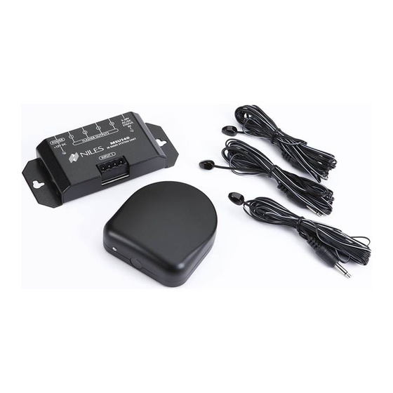
E M O T E O N T R O L N Y W H E R E Introduction The Remote Control Anywhere! Kit enables you to operate your remote con- trolled audio/video equipment from vir- Connection Hub Table-Top Sensor tually any location. - Page 4 E M O T E O N T R O L N Y W H E R E Tools Needed • Pencil • Drywall saw • Standard screwdriver • Phillips screwdriver • Wire strippers • Drill (and assorted bits)
-
Page 5: Getting Started
E M O T E O N T R O L N Y W H E R E Getting Started While the Remote Control Anywhere! Kit is compatible with most brands of audio/video components, there are exceptions. should perform a temporary hook-up to test for compatibility before you conceal wire or permanently mount any parts. - Page 6 Don’t force the scalloped side of the connector plug into the smooth side of the socket. To Niles To 12VDC Power Supply IR Flasher Plugged into an switched AC Outlet.
- Page 7 E M O T E O N T R O L N Y W H E R E Step 3 – Connecting the Sensor Cable to the Table-Top Sensor Pull out the removable connector from the bottom of the table-top sensor. Insert each wire into the appropriate hole on the removable connector plug (Figure 3), and snap the lock- ing tab down.
- Page 8 E M O T E O N T R O L N Y W H E R E Step 4 – Connecting the 12VDC In-Line Power Supply “TECH TIP” and MicroFlashers Plug the MicroFlashers into any of the sockets labeled FLASHER OUTPUTS on the connection hub (Figure 5).
- Page 9 E M O T E O N T R O L N Y W H E R E Step 5 – Mounting a MicroFlasher to A/V Components Make sure all of your remote controls have batteries and that they are able to operate the A/V components. Locate a place for the remote control that is within arm’s length of the A/V components, yet cannot directly control them.
- Page 10 MicroFlasher and place the MicroFlasher in that location. If you get no response at all, call Niles Technical Support at 1-800-289-4434 (M-F 8:00 AM – 7:00 PM ET). Step 6 – Mounting the Connection Hub...
- Page 11 E M O T E O N T R O L N Y W H E R E Additional Additional Flashers Flashers REMOTE CONTROL ANYWHERE! KIT REMOTE CONTROL ANYWHERE! KIT CONNECTION HUB CONNECTION HUB Figure 8: Removing Cables Figure 9: Removing Sensor Connector Additional Sensors Additional Sensors Figure 10A &...
- Page 12 IMPORTANT If you have doubts about whether you are capable of installing a Niles Remote Control Anywhere! Kit in your walls, consult a Niles dealer or professional installer. They have special tools, techniques, and experience to make the impossible possible. The installer can...
- Page 13 E M O T E O N T R O L N Y W H E R E Step 8 – Reconnecting the Connection Hub NOTE Reconnect the sensor plug, flashers and power supply as Make sure that the outlined in steps 2, 3 and 4 (Figure 11). stripped ends of the That’s it! Now you are ready to control your audio/video wire do not come...
-
Page 14: System Operation
E M O T E O N T R O L N Y W H E R E Normal Operation To control your audio/video components, simply aim your remote control at the table-top sensor. If you are within range (and your remote control’s batteries are fresh), the LED on the sensor will flash a bright blue color each time you press a button on the remote (Figure 12). -
Page 15: Optional Accessories
Although the Remote Control Anywhere! Kit includes three MicroFlashers, the connection hub can accommodate up to four. Order model MF1 (Stock# FG01019) from your autho- rized Niles dealer for each additional A/V component you wish to control. Figure 13: Connecting the... - Page 16 The 12VDC output plug is inserted into the connection hub’s Status Input (Figure 13). Additional Sensors The Remote Control Anywhere! Kit includes one table-top sensor. Niles also makes a variety of sensors for virtually any application. See your Niles dealer for more information.
-
Page 17: Running Sensor Cable In New Construction
E M O T E O N T R O L N Y W H E R E Running Sensor Cable in New Construction Scheduling and Preparation Plan to schedule the sensor wiring after the electrical wiring is finished. That way you can avoid cable routes which could potentially induce interference over the sensor cable. - Page 18 E M O T E O N T R O L N Y W H E R E Safety First! Wear gloves, safety goggles and head protection when drilling. Avoid nails, they ruin bits and they can cause injury. Pay partic- ular attention when using “hole-hogs”...
-
Page 19: Concealing Sensor Cable In Existing Walls
E M O T E O N T R O L N Y W H E R E Pulling the Cable Whenever you run the cable farther than 4-1/2 feet from a hole in a stud or joist (open attic space, going up walls, etc.), fasten the cable to the joists or studs using cable clamps or appropriately sized cable staples. - Page 20 E M O T E O N T R O L N Y W H E R E Exterior walls are different. They must insulate the house from the heat and cold outside, so they are stuffed with insulation. The national building code requires that the hollow wall space in exterior walls be broken by a horizontal stud placed between the vertical studs.
- Page 21 E M O T E O N T R O L N Y W H E R E When you don’t have access above or below the wall, try to estimate the existing cable and pipe locations from the positions of electrical outlets and plumbing fixtures on both sides of the wall.
- Page 22 E M O T E O N T R O L N Y W H E R E When you are dealing with the Figure 15: Routing Wire Around a Door unknown because of the struc- ture of your home, or with diffi- cult materials to patch the wall, such as plaster, lath and plaster, faux finishes, wallpaper etc., be...
-
Page 23: Specifications
E M O T E O N T R O L N Y W H E R E Specifications IR Receiving Angle 30° off-axis (horizontal and vertical) at 20' MSU140 Mounting IR System Table-top Compatible with virtually all brands of remotes Wiring Requirements using carrier frequencies between 26 and 105kHz. - Page 24 Niles Audio Corporation www.nilesaudio.com ©2004 Niles Audio Corporation. All rights reserved. Niles, the Niles logo, IntelliPad and Blending High Fidelity and Architecture are registered trademarks of Niles Audio Corporation. MicroFlasher is a trademark of Niles 12331 S.W. 130 Street Audio Corporation. Because we strive to improve our products. All other trademarks are the property of their Miami, Florida, 33186 respective owners.
Need help?
Do you have a question about the RCA2 and is the answer not in the manual?
Questions and answers