Table of Contents
Advertisement
Advertisement
Table of Contents

Related Manuals for Furuno FR-2115/2125


Summary of Contents for Furuno FR-2115/2125
- Page 1 MARINE RADAR FR-2115/2125 MODEL...
- Page 2 9 - 5 2 , A s h i h a r a - c h o , N i s h i n o m i y a , J a p a n T e l e p h o n e : 0 7 9 8 - 6 5 - 2 1 1 1 T e l e f a x : 0 7 9 8 - 6 5 - 4 2 0 0...
- Page 3 Note: If the antenna unit is installed at a close distance in front of the wheel house, your administration may require halt of transmission within a certain sector of antenna revolution. This is possible—Ask your FURUNO representative or dealer to provide this feature. ELECTRICAL SHOCK HAZARD Construct a suitable service platform from which to install the antenna unit.
- Page 4 WARNING Be sure that the power supply is compatible with the voltage rating of the equipment. Connection of an incorrect power supply can cause fire or equipment damage. The voltage rating of the equipment appears on the label above the power connector. Use only the specified power cable.
-
Page 5: Table Of Contents
TABLE OF CONTENTS EQUIPMENT LISTS ... SYSTEM CONFIGURATION ... MOUNTING Scanner Unit ... 1-1 Display Unit ... 1-5 WIRING Scanner Unit ... 2-1 Display Unit ... 2-6 Changing AC Power Specification for Display Unit ... 2-12 INITIALIZATION AND ADJUSTMENT Tuning Initialization ... 3-1 Accessing Menus for Initialization and Adjustment ... - Page 6 EQUIPMENT LISTS Standard Supply — — — — — — — — — — — — —...
-
Page 7: Optional Equipment
Standard Supply l l a Optional Equipment c t i c t i i f i t l l a — — — — — , ) t , ) t , ) t , ) t , ) t , ) t , ) t , ) t... -
Page 8: Scanner Unit
SYSTEM CONFIGURATION SCANNER UNIT FR-2115: XN12AF-RSB-0074-062 XN12AF-RSB-0075-062 XN20AF-RSB-0074-062 XN20AF-RSB-0075-062 XN24AF-RSB-0074-062 XN24AF-RSB-0075-062 FR-2125: XN12AF-RSB-0074-063 XN12AF-RSB-0075-063 XN20AF-RSB-0074-063 XN20AF-RSB-0075-063 XN24AF-RSB-0074-063 XN24AF-RSB-0075-063 IEC-61162-1 Serial Data Navigator (Input/Output) IEC-61162-1 Serial Data Speed Log (Input) Gyrocompass Option DISPLAY UNIT RDP-124 ARPA ARP-26 Gyro Converter GC-8 Video Plotter RP-26 DC spec Rectifier... -
Page 9: Mounting Considerations
1.1 Scanner Unit Mounting considerations • The scanner unit is generally installed either on top of the wheelhouse or on the radar mast, on a suitable platform. Locate the scanner unit where there is a good all-round view. (a) On bridge •... - Page 10 Assembling the scanner unit The scanner unit consists of the scanner radiator and the scanner unit chassis, and they are packed separately. Fasten the scanner radiator to the scanner unit chassis as follows: 1. For the XN20AF, XN24AF, attach two guide pins to the underside of the scan- ner radiator.
- Page 11 Antenna radiator Guide pin (XN20AF, XN24AF only) Figure 1-3 Fastening the radiator to the radiator bracket Fastening the scanner unit to the mounting platform The scanner unit may be assembled before hoisting it to the mounting platform. However, do not lift the scanner unit by the radiator. Always hold the unit by its housing.
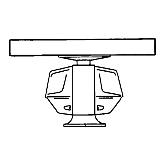
- Page 12 4. Place the scanner unit on the rubber mat orienting the unit so the bow mark on its base is facing the ship’s bow. Bow mark Figure 1-4 Scanner unit, front view 5. Fasten the scanner unit to the mounting platform with M12x60 hex bolts, nuts, flat washers and seal washers.
-
Page 13: Display Unit
1.2 Display Unit Before mounting the display unit If Gyro Converter GC-8 (option) is to be used, install and setup the GYRO CON- VERTER Board before mounting the display unit, because of the difficulty involved in doing it after the display unit is installed. Instructions for installation and setup are in Chapter 4. - Page 14 4. While one person is holding the mounting base at the sides, pull the handle on the underside of the control head to draw the display unit toward you until you hear a click. CAUTION Use two people to complete this step.
- Page 15 b) While pushing the stopper, set the catch on the display unit in the hole at the front edge of the stay. Figure 1-9 Setting catch to hole in stay c) Release hand from stopper. Figure 1-10 Stay fixed 6. Fasten the display unit to the mounting location at front fixing holes (2 points) with M10 bolts, nuts and flat washers, using the pipe box spanner (supplied).
- Page 16 (2)Remove the cover by grasping the knob on the top of the cover. *Screw (M3x8, 5 pcs.) Slide forward Figure 1-11 How to dismount the PTU cover 9. Fasten the display unit to the mounting location at rear fixing holes (2 points) with M10 bolts, nuts and flat washers, using the pipe box spanner (supplied) 10.Close the PTU board cover.
- Page 17 Separating the control head The control head connects to the display unit with a connection cable, thus it can be located where desired, using the separate control head kit (option). Follow the procedure on the next page to separate the control head from the display unit. Separate type control head kit (Type: OP03-151, No.: 008-485-530) p i l p i l...
- Page 18 3. Lower the monitor. 4. Unfasten the M4 screw fixing the ground terminal of the connection cable. 5. Push the monitor forward until you hear a click. 6. Unscrew four screws fixing the top cover of the display unit. 7. Remove three clamps fixing the connection cable in the monitor unit. 8.
- Page 19 4. Replace the cable assy. with cable assy. UL2464SB2-0P/1P (10 m, supplied) as below and reassemble the control head. 5. Attach warning label to the bottom plate. P312 FX Connector Upset Screw M6X12 (2 pcs.) KB Clamp Handle Replace with cable assy.
- Page 20 7. Plug in two connectors of connection cable (P412, J583: See illustration on the previous page.) 8. Lower the monitor. 9. Attach the monitor front cover (option) to the place the panel cover have been, using the screw for the panel cover. 10.Attach rubber to feet to the bottom of the keyboard if the keyboard is not going to be permanently fixed.
- Page 21 2.1 Scanner Unit The magnetron in the transceiver module will de- magnetize if it contacts ferrous material. When dismounting the transceiver module, lay it on its side or on top of non-ferrous material as shown below. 1. Open the scanner unit cover. 2.
- Page 22 4. Unfasten the four fixing bolts on the cable gland at the base of the scanner unit. Remove clamping ring, rubber gasket and washers. From left: Clamping ring, washer, rubber gasket and washer Signal cable Figure 2-2 Scanner unit, front view, cover removed 5.
- Page 23 12.If the scanner is mounted 2 or more left of ship’s bow, adjust the position of S901 so it becomes “on” (contact between #1 and #2 on pcb MP-3795). To access S901, open the bow side cover; S901 is above the drive gear. RTB801 Bow mark Figure 2-4 Scanner unit, front view...
- Page 24 Fabricating signal cable S03-75 1. Remove the vinyl sheath by 450 mm. 2. Slide the clamping ring, washer, rubber gas- ket and washer onto the signal cable in that order. 3. Unravel the outer shield to expose the cores in the outer layer. Then, unravel the inner shield to expose the cores in the inner layer.
- Page 25 Fabricating signal cable 1. Remove the anti-corrosive sheath by 500 mm. Remove the armor and vinyl sheath leaving 50 mm each approximately. 2. Fold back the armor and trim to suitable length. Then, slide the washer, rubber gas- ket, washer and clamping ring onto the cable in that order.
- Page 26 2.2 Display Unit Two cables are terminated at the display unit: the signal cable S03-74 or S03-75 and the power cable. The signal cable comes with a connector preattached to it for connection to the display unit. Fabricate the power cable as below. Fabricating the AC power cable (supplied) 1.
- Page 27 Fabricating the DC power cable (CVV-S 8 x 2C, option) 1. Remove the vinyl sheath by 100 mm. 2. Unravel the braided shield 60 mm from end of cable. 3. Remove the jute tape and inclusion from cable. 4. Expose the cores by 50 mm. 5.
- Page 28 Leading in cables to the display unit The cable clamp may be positioned within the display unit (default arrangement), outside the display unit or at the bottom of the display unit (when using console mount, for example). When the cable clamp is located outside or beneath the dis- play unit, use the bottom clamp front plate and bottom clamp rear plate (supplied with installation materials).
- Page 29 Cable fed from outside display unit (A) Rear clamp base Figure 2-13 Clamp position outside display unit (display unit right side view) • Place shielding foam between cables inside of display unit, and then attach foam to chassis. • Fill unused clamp holes with shielding foam. Cables fed from bottom of display unit (for console mount) Lead in cables through the cable clamp at the rear of the console and ground their shields in the cable clamp.
- Page 30 Connections Open the display unit and fix it with the stay. (For procedure see page 1-5.) Re- move the shield cover from the INT Board. Connect signal, power, gyro and log cables as shown below. Optional equipment are connected to the INT Board. Be sure to ground the display unit.
- Page 31 Connectors on the INT Board Table 2-1 Connectors on the INT Board Note: How to attach NH connector is shown on the next page. . t i 2-11...
-
Page 32: Changing Ac Power Specification
How to attach NH connector HOW TO ATTACH NH CONNECTOR TO SIGNAL CABLE NH connector wire NH connector housing 1 Insert NH connector wire into NH connector housing. Figure 2-16 How to attach NH connector 2.3 Changing AC Power Specification For 100 VAC or 220 VAC power, add or delete jumper wires on the PTU Board and change the power fuses inside the display unit as shown in the table below accord- ing to ship’s mains. -
Page 33: Tuning Initialization
INITIALIZATION AND ADJUSTMENT 3.1 Tuning Initialization Tune the radar as follows: Press [RADAR MENU] [0] [0] [2] [0] [0] [0] (TUNE INITIALIZE on RADAR 3 menu) and press the [ENT] key. Also, confirm that "2. MODEL" is set to "FR-2115, 2125" on the INITIAL SETTING 4 menu, following paragraph 3.2 and then pressing [RADAR MENU], [0],[0],[0],[2],[0],[0],[0]. -
Page 34: Heading Alignment
3. Adjust R21 on the INT Board so the value of TP6 is 4 Vpp. (For remote dis- play, adjust R134 on the INT Board.) 3.4 Heading Alignment You have mounted the scanner unit facing straight ahead in the direction of the bow. -
Page 35: Adjusting Sweep Timing
3.5 Adjusting Sweep Timing Sweep timing differs with respect to the length of the signal cable between the scanner unit and the display unit. Adjust sweep timing at installation to prevent the following symptoms: • The echo of a "straight" target (for example, pier), on the 0.25 nm range, will appear on the display as being pulled inward or pushed outward. -
Page 36: Confirming Magnetron Heater Voltage
3.7 Confirming Magnetron Heater Voltage Magnetron heater voltage is adjusted at the factory. However, confirm that it is within the prescribed rating. Table 3-1 Magnetron heater voltage rating 1. Press [RADAR MENU] [0] [0] [0] [2] [0] to open the INITIAL SETTING2 menu. 2. -
Page 37: Initial Setting Menus
3.8 Initial Setting Menus The INITIAL SETTING menus (four menus) and the OWN SHIP INFORMATION menu setup the radar according to expected usage, authorities specification, ship's characteristics, operator's preference, etc. Set items on each menu in accor- dance with regulations/operator's preference. After entering initial settings, reset the power. - Page 38 INITIAL SETTING1 menu Keying sequence: [RADAR MENU] [0] [0] [0] [2] HL ALIGN: Aligns heading. TIMING ADJ: Adjusts sweep timing. ANT HGT: Enter height of scanner above water. Select from 5 m, 7 m, 10 m, 15 m, 20 m, or more than 30 m. LOG PULSE: Enter speed log's pulse rate.
- Page 39 ECHO AVG W/O GYRO: Echo averaging can be turned on without gyrocompass connection. HEAD UP TB SCALE: Bearing scale may be shown in degrees or compass points in the head-up mode. CTR ECHO STRETCH: Turn on to enlarge echoes in the range up to the first range ring.
-
Page 40: Gyro Converter Gc-8
INSTALLATION OF OPTIONAL EQUIPMENT 4.1 Gyro Converter GC-8 The Gyro Converter GC-8, incorporated inside the radar display unit, converts analog gyrocompass reading into digital coded bearing data for display on the radar display. This section explains how to install and setup the GC-8 (mainly consisting of the GYRO CONVERTER Board) and set it up according to gyrocompass connected. - Page 41 4) Connect the GYRO CONVERTER Board to the INT Board (cables supplied with GC-8) as shown below. INT BOARD 03P9252 Figure 4-2 Display unit, inside view 5) Confirm gyrocompass specifications and set up the DIP switches and jumper wires on the GYRO CONVERTER Board according to gyrocompass connected: •...
- Page 42 Connection of external power supply An external power supply is necessary when the repeater signal is step-by-step type and the step voltage is below 20V or output voltage is less than 5 W. 1. Cut jumper wire JP1 on the GYRO CONVERTER Board when an external power supply is used.
- Page 43 Setting method 1: by gyrocompass specifications - l l - f l & t t i a l i l l a...
- Page 44 Setting method 2: by make and model of gyrocompass e l l i a l ) - ( ) - ( ) - ( i a l / I I I I I , ) - e l l ) - ( ) - ( , ) - : Set JP4 and JP5 according to the voltage of the external power supply.
- Page 45 Location of DIP switches, jumper wires on the GYRO CONVERTER Board (Rotor voltage) (Stator voltage) (Gyro type) Fuse (2A) (Stator signal input) (Rotor signal input, external power input) Figure 4-4 GYRO CONVERTER Board Setting the heading readout on the radar display Confirm that the gyrocompass is giving a reliable readout.
-
Page 46: Arp Board Arp-26
4.2 ARP Board ARP-26 The ARP Board ARP-26, which provides ARPA functions, is an optional circuit board which is accommodated in the display unit of the FR-2105 series radar. Necessary Parts: ARP-26-2E (008-485-500) Installation of the ARP board 1. Remove the bottom cover of the display unit by unfastening four screws. 2. - Page 47 ARP board adjustment 1. Turn the GAIN, A/C SEA and A/C RAIN controls fully counterclockwise, and then transmit on the 12 nm range. 2. Connect a digital multimeter between TP7(+) and TP6(-) on the ARP Board. Figure 4-6 ARP Board (18P9002B) 3.
- Page 48 Final check Connect a gyrocompass and a log to the radar and place the radar under transmit state. Confirm that LEDs CR9, CR10, CR11, CR12, CR15 and CR16 on the ARP Board are off. If ship's speed is zero, or other signal is not being input, correspond- ing LED will light.
-
Page 49: Rp Board Rp-26
4.3 RP Board RP-26 The RP Board RP-26, which providesvideo plotter functions, consists of a circuit board and a card drive both of which are accommodated in the display unit of the FR-2105 series radar. Table top/console type Necessary Parts: RP-26-T-2E (008-485-520) 1. - Page 50 4. Unfasten the front panel from the display pedestal. 5. Pass the connector from the card case through the hole in the display pedestal. Front panel Figure 4-10 Display pedestal 6. Set the RP Board (14P0298) in the top slot of the pcb card case. See page 4-7 for the location of the pcb card case.
- Page 51 10.Fasten the front panel on the display pedestal. 11. Retract the stay to close the display unit. 12.Fasten the right arm cover. Separate type control head Necessary parts: RP-26-Z-2E (Code no. 008-491-400) 1. Lift the monitor. See Chapter 1 for instructions. 2.
- Page 52 Control section Control section front panel Pan Head Screw M2.6X5 (2 pcs.) Figure 4-13 Display pedestal, front view 5. Loosen six screws to remove the front panel on the display pedestal. 6. Set the RP Board (14P0298) in the top slot of the pcb card case. 7.
-
Page 53: Performance Monitor Pm-30
10.Fasten the front panel of the display pedestal. 11. Fasten the ground wire to the location shown in Figure 4-14. 12.Close the monitor. 4.4 Performance Monitor PM-30 Necessary parts: PM-30 and OP03-150 (Code no. 008-485-490) 1. Lift the monitor. See Chapter 1 for instructions. 2. -
Page 54: Alarm Kit
4.5 Alarm Kit Necessary parts: OP03-156 (Code no. 008-500-650) The alarm kit mainly consists of a circuit board and connection cables, and pro- vides alarm output to ship’s bridge alarm system. Procedure Refer to the figure below for parts locations. 1. - Page 55 J451 INT Board Existing cable tie 03P9252 Figure 4-16 Display unit, inside view HOW TO INSULATE THE POWER CABLE Shrink Tubing Solder 20 mm 1 Make length of 2 Solder power cable to signal cable. shrink tubing 20 mm; slip tubing onto wiring. 4-16 Pass cable through here.
-
Page 56: Ac-Dc Conversion Kit
4.6 AC-DC Conversion Kit The AC-DC Conversion Kit enables conversion from AC power to DC power, and mainly consists of a circuit board and filter. t l i 1. Slide the monitor forward until the PTU Board and filter are in view and easily accessed.
Need help?
Do you have a question about the FR-2115/2125 and is the answer not in the manual?
Questions and answers