Viking VMOS200 Service Manual
Hide thumbs
Also See for VMOS200:
- Reference manual (9 pages) ,
- Installation instructions (4 pages) ,
- Installation manual (4 pages)
Table of Contents
Advertisement
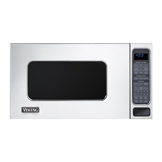
(DMOS200 model shown)
In the interest of user-safety the oven should be restored to its original condition and only parts identical to those specified
should be used.
WARNING TO SERVICE PERSONNEL: Microwave ovens contain circuitry capable of producing very high voltage and
current. Contact with the following parts may result in a severe, possibly fatal, electrical shock. (Inverter unit that includes
High Voltage Capacitor, High Voltage Power Transformer, High Voltage Rectifier and Heat sink etc., and Magnetron, High
Voltage Harness etc..)
BEFORE SERVICING ...................................................................................................... INSIDE FRONT COVER
WARNING TO SERVICE PERSONNEL ................................................................................................................2
MICROWAVE MEASUREMENT PROCEDURE .....................................................................................................3
FOREWORD AND WARNING ................................................................................................................................5
PRODUCT SPECIFICATIONS ...............................................................................................................................6
GENERAL INFORMATION ...................................................................................................................................6
OPERATION .........................................................................................................................................................8
TROUBLESHOOTING GUIDE ............................................................................................................................. 12
TEST PROCEDURE ............................................................................................................................................ 14
TOUCH CONTROL PANEL ASSEMBLY ............................................................................................................. 24
COMPONENT REPLACEMENT AND ADJUSTMENT PROCEDURE .................................................................. 31
PICTORIAL DIAGRAM ........................................................................................................................................ 37
POWER UNIT CIRCUIT ....................................................................................................................................... 38
LSI UNIT CIRCUIT ............................................................................................................................................... 39
PRINTED WIRING BOARD ................................................................................................................................. 40
PARTS LIST ........................................................................................................................................................ 41
PACKING AND ACCESSORIES ......................................................................................................................... 45
Range Corporation
111 Front St., Greenwood, MS 38930
Tel: (888) 845-4641
SERVICE MANUAL
COOK
TABLE OF CONTENTS
MICROWAVE OVEN
DMOS200
MODELS
CDMOS200
VMOS200
CVMOS200
This document has been published to be used for after
sales service only.
The contents are subject to change without notice.
DMOS200
CDMOS200
VMOS200
CVMOS200
S72M194DMOS2E
Page
Advertisement
Table of Contents

Related Manuals for Viking VMOS200


Summary of Contents for Viking VMOS200
-
Page 1: Table Of Contents
DMOS200 CDMOS200 VMOS200 CVMOS200 SERVICE MANUAL S72M194DMOS2E MICROWAVE OVEN COOK DMOS200 MODELS CDMOS200 VMOS200 CVMOS200 (DMOS200 model shown) In the interest of user-safety the oven should be restored to its original condition and only parts identical to those specified should be used. -
Page 2: Precautions To Be Observed Before And During Servicing To Avoid Possible Exposure To Excessive Microwave Energy
Before servicing an operative unit, perform a microwave emission check as per the Microwave Measure- ment Procedure outlined in this service manual. If microwave emissions level is in excess of the specified limit, contact Viking Service immediately @ 1-888-845-4641. If the unit operates with the door open, service person should (1) tell the user not to operate the oven and (2) contact VIKING, plus the Department Of Health, Canada and/or the Food and Drug Administration's Center for Devices and Radiological Health immediately. - Page 3 CDMOS200 DMOS200 VMOS200 CVMOS200 Notes...
-
Page 4: Warning To Service Personnel
CDMOS200 DMOS200 VMOS200 CVMOS200 WARNING TO SERVICE PERSONNEL Microwave ovens contain circuitry capable of pro- ducing very high voltage and current, contact with following parts may result in a severe, possibly fatal, electrical shock. (Example) High Voltage Capacitor, High Voltage Power Trans- former, Magnetron, High Voltage Rectifier Assem- bly, High Voltage Harness etc.. -
Page 5: Microwave Measurement Procedure
CDMOS200 DMOS200 VMOS200 CVMOS200 MICROWAVE MEASUREMENT PROCEDURE (CANADA) After adjustment of the door switches are completed individually or collectively, switch test and microwave leakage test must be performed with survey instrument and test result must be confirmed to meet the requirement of the performance standard for microwave ovens as undermentioned. - Page 6 CDMOS200 DMOS200 VMOS200 CVMOS200 MICROWAVE MEASUREMENT PROCEDURE (USA) A. Requirements: 1) Microwave leakage limit (Power density limit): The power density of microwave radiation emitted by a microwave oven should not exceed 1mW/cm at any point 5cm or more from the external surface of the oven, measured prior to acquisition...
- Page 7 VMOS200 CVMOS200 FOREWORD OPERATION This Manual has been prepared to provide Viking Service Personnel with Operation and Service Information for the Viking Microwave Ovens, DMOS200, CDMOS200, VMOS200, CVMOS200 . TROUBLESHOOTING GUIDE AND It is recommended that service personnel carefully study the entire text of...
-
Page 8: General Information
CDMOS200 DMOS200 VMOS200 CVMOS200 SPECIFICATION ITEM DESCRIPTION Power Requirements 120 Volts / 13.0 Amperes/1500Watts 60 Hertz Single phase, 3 wire grounded Power Output 1100 watts (IEC-705 TEST PROCEDURE) Operating frequency of 2450MHz Case Dimensions Width 24" Height 13-3/8" Depth 19-1/8"... -
Page 9: Oven Diagram
TOUCH CONTROL PANEL COOK NOTE: The directed features are disabled after one minute when the oven is (VMOS200 model shown) not in use. These features are automatically enabled when the door is opened and closed or the STOP/ CLEAR pad is pressed. -
Page 10: Operation
CDMOS200 DMOS200 VMOS200 CVMOS200 OPERATION DESCRIPTION OF OPERATING SEQUENCE The following is a description of component functions during the primary switch and primary and is mechanically oven operation. associated with the door so that it will function in the following sequence. - Page 11 CDMOS200 DMOS200 VMOS200 CVMOS200 2. The coil of shut-off relay (RY-1) is energized, the turntable motor are turned on, but the power transformer SENSOR COOKING CONDITION is not turned on. 3. After about 16 seconds, the cook relay (RY-2) is Using the SENSOR function, food is cooked without figuring energized.
- Page 12 CDMOS200 DMOS200 VMOS200 CVMOS200 SCHEMATIC NOTE: CONDITION OF OVEN 1. DOOR CLOSED 2. CLOCK APPEARS ON DISPLAY S E C ONDAR Y P R IMAR Y S WIT C H S WIT C H N.O. C OM. N.O. C OM.
-
Page 13: Description And Function Of Components
CDMOS200 DMOS200 VMOS200 CVMOS200 DESCRIPTION AND FUNCTION OF COMPONENTS DOOR OPEN MECHANISM open, the monitor fuse blows simultaneously with closing The door is opened by pushing the open button on the control of the monitor switch contacts. panel, refer to the Figure D-1. When the open button is... -
Page 14: Troubleshooting Guide
CDMOS200 DMOS200 VMOS200 CVMOS200 TROUBLESHOOTING GUIDE Never touch any part in the circuit with your hand or an uninsulated tool while the power supply is connected. When troubleshooting the microwave oven, it is helpful to follow the Sequence of Operation in performing the checks. Many of the possible causes of trouble will require that a specific test be performed. -
Page 15: Test Procedure
CDMOS200 DMOS200 VMOS200 CVMOS200 CK = Check / RE = Replace RE RE A B C D E E F F G H RE RE CK I CK CKCK J K L TEST PROCEDURE POSSIBLE CAUSE DEFECTIVE PARTS PROBLEM CONDITION... - Page 16 CDMOS200 DMOS200 VMOS200 CVMOS200 TEST PROCEDURES PROCEDURE COMPONENT TEST LETTER 4. To test for an open filament, isolate the magnetron from the high voltage circuit. A continuity check across the magnetron filament leads should indicate less than 1 ohm. 5. To test for a shorted magnetron, connect the ohmmeter leads between the magnetron filament leads and chassis ground.
- Page 17 CDMOS200 DMOS200 VMOS200 CVMOS200 TEST PROCEDURES PROCEDURE COMPONENT TEST LETTER HIGH VOLTAGE RECTIFIER TEST 1. Disconnect the power supply cord, and then remove outer case. 2. Open the door and block it open. 3. Discharge high voltage capacitor. 4. Isolate the rectifier from the circuit. Using the highest ohm scale of the meter, read the resistance across the terminals and observe, reverse the leads to the rectifier terminals and observe meter reading.
- Page 18 CDMOS200 DMOS200 VMOS200 CVMOS200 TEST PROCEDURES PROCEDURE COMPONENT TEST LETTER CAUTION: IF THE TEMPERATURE FUSE INDICATES AN OPEN CIRCUIT AT ROOM TEMPERA- TURE, REPLACE TEMPERATURE FUSE. PRIMARY AND SECONDARY SWITCH TEST 1. Disconnect the power supply cord, and then remove outer case.
- Page 19 CDMOS200 DMOS200 VMOS200 CVMOS200 TEST PROCEDURES PROCEDURE COMPONENT TEST LETTER 5. Reconnect all leads removed from components during testing. 6. Reinstall the outer case (cabinet). 7. Reconnect the power supply cord after the outer case is installed. 8. Run the oven and check all Screw Driver functions.
- Page 20 CDMOS200 DMOS200 VMOS200 CVMOS200 TEST PROCEDURES PROCEDURE LETTER COMPONENT TEST The following symptoms indicate a defective key unit. a) When touching the pads, a certain pad produces no signal at all. b) When touching a number pad, two figures or more are displayed.
- Page 21 CDMOS200 DMOS200 VMOS200 CVMOS200 TEST PROCEDURES PROCEDURE COMPONENT TEST LETTER 6. Re-install the outer case (cabinet). 7. Reconnect the power supply cord after the outer case is installed. 8. Run the oven and check all functions. RELAY TEST 1. Disconnect the power supply cord, and then remove outer case.
- Page 22 CDMOS200 DMOS200 VMOS200 CVMOS200 TEST PROCEDURES PROCEDURE COMPONENT TEST LETTER FOIL PATTERN ON THE PRINTED WIRING BOARD TEST To protect the electronic circuits, this model is provided with a fine foil pattern added to the primary on the PWB, this foil pattern acts as a fuse.
- Page 23 CDMOS200 DMOS200 VMOS200 CVMOS200 TEST PROCEDURES PROCEDURE COMPONENT TEST LETTER AH SENSOR TEST Checking the initial sensor cooking condition Warning: The oven should be fully assembled before following procedure. 1) The oven should be plugged in at least two minutes before sensor cooking.
- Page 24 CDMOS200 DMOS200 VMOS200 CVMOS200 TEST PROCEDURES PROCEDURE COMPONENT TEST LETTER CHECKING CONTROL UNIT (1) Disconnect the power supply cord, and then remove outer case. (2) Open the door and block it open. (3) Discharge high voltage capacitor. (4) Disconnect the sensor connector that is mounted to control panel.
- Page 25 CDMOS200 DMOS200 VMOS200 CVMOS200 TEST PROCEDURES PROCEDURE COMPONENT TEST LETTER NOISE FILTER TEST 1. Disconnect the power supply cord, and then remove outer case. 2. Open the door and block it open. 3. Discharge high voltage capacitor. 4. Disconnect the leads to the primary of the power transformer.
-
Page 26: Touch Control Panel Assembly
CDMOS200 DMOS200 VMOS200 CVMOS200 TOUCH CONTROL PANEL ASSEMBLY OUTLINE OF TOUCH CONTROL PANEL 4) Relay Circuit The touch control section consists of the following units. A circuit to drive the magnetron, fan motor, turntable motor and light the oven lamp. - Page 27 CDMOS200 DMOS200 VMOS200 CVMOS200 LSI(IXA098DR) The I/O signal of the LSI(IXA098DR) is detailed in the following table. Pin No. Signal Description COM5 Common data signal : COM11. Connected to LCD signal COM11. COM4 Common data signal : COM12. Connected to LCD signal COM12.
- Page 28 CDMOS200 DMOS200 VMOS200 CVMOS200 Pin No. Signal Description INT0 Signal synchronized with commercial power source frequency. H : GND This is the basic timing for time processing of LSI. L : -5V 16.7 msec. Key strobe signal. Signal applied to touch-key section. A pulse signal is input to AIN7, P14, P15, P16 and P17 terminal while one of G1 line keys on key matrix is touched.
- Page 29 CDMOS200 DMOS200 VMOS200 CVMOS200 Pin No. Signal Description AIN5 AH sensor input. This input is an analog input terminal from the AH sensor circuit, and connected to the A/ D converter built into the LSI. AIN4 Used for initial balancing of the bridge circuit (absolute humidity sensor). This input is an analog input terminal from the AH sensor circuit, and connected to the A/D converter built into the LSI.
- Page 30 CDMOS200 DMOS200 VMOS200 CVMOS200 103-142 Segment data signal. SEG39-SEG0 Connected to LCD. The relation between signals and LCD are as follows: LSI signal (Pin No.) LCD segment LSI signal (Pin No.) LCD segment SEG 39 (103) ......SEG 1 SEG 19 (123) ......SEG 21 SEG 38 (104) ......
- Page 31 CDMOS200 DMOS200 VMOS200 CVMOS200 ABSOLUTE HUMIDITY SENSOR CIRCUIT With this voltage given, the switches SW1 to SW5 in the (1) Structure of Absolute Humidity Sensor LSI are turned on in such a way as to change the The absolute humidity sensor includes two thermistors as resistance values in parallel with R107 ~ R111 of IC2 .
- Page 32 CDMOS200 DMOS200 VMOS200 CVMOS200 TOUCH CONTROL PANEL SERVICING 1. Precautions for Handling Electronic Components 5) Re-connect the power supply cord after the outer This unit uses CMOS LSI in the integral part of the case is installed. circuits. When handling these parts, the following 6) Run the oven and check all functions.
-
Page 33: Component Replacement And Adjustment Procedure
CDMOS200 DMOS200 VMOS200 CVMOS200 COMPONENT REPLACEMENT AND ADJUSTMENT PROCEDURE WARNING AGAINST HIGH VOLTAGE: Microwave ovens contain circuitry capable of producing very high voltage and current, contact with following parts may result in severe, possibly fatal, electric shock. (Example) High Voltage Capacitor, Power Transformer, Magnetron, High Voltage Rectifier Assembly, High Voltage Harness etc.. -
Page 34: Pictorial Diagram
CDMOS200 DMOS200 VMOS200 CVMOS200 CAUTION: 1. DISCONNECT OVEN FROM POWER SUP PLY BEFORE REMOVING OUTER CASE. 2. DISCHARGE THE HIGH VOLTAGE CA- PACITOR BEFORE TOUCHING ANY OVEN COMPONENTS OR WIRING. Special screw NOTE: When replacing the outer case, the 2 special Torx screws must be reinstalled in the same locations. -
Page 35: Lsi Unit Circuit
CDMOS200 DMOS200 VMOS200 CVMOS200 OVEN LAMP AND LAMP SOCKET REMOVAL 1. Disconnect the power supply cord and remove outer case. Oven lamp 2. Open the door and block it open. socket 3. Discharge high voltage capacitor. 4. Remove the oven lamp from the oven lamp socket. -
Page 36: Cooling Fan Motor Removal
CDMOS200 DMOS200 VMOS200 CVMOS200 COOLING FAN MOTOR REMOVAL REMOVAL CAUTION: 1. Disconnect the power supply cord and then remove outer * Do not reuse the removed fan blade because the hole case. (for shaft) may be larger than normal. 2. Open the door and block it open. -
Page 37: Door Replacement
CDMOS200 DMOS200 VMOS200 CVMOS200 3. Secure latch hook (with two (2) mounting screws) to oven and check continuity of the monitor circuit. Refer to chapter flange. "Test Procedure" and Adjustment procedure. 4. Make sure that the monitor switch is operating properly DOOR SENSING SWITCH/PRIMARY SWITCH/SECONDARY SWITCH AND MONITOR SWITCH ADJUSTMENT 1. - Page 38 CDMOS200 DMOS200 VMOS200 CVMOS200 SEALER FILM 6. Re-install choke cover to door panel by pushing. Installation Note: After any service to the door; 1. Put the adhesive tape on the backing film of the sealer (A) Make sure that door sensing switch and secondary film as shown in Fig.
- Page 39 CDMOS200 DMOS200 VMOS200 CVMOS200 MONIT...
- Page 40 CDMOS200 DMOS200 VMOS200 CVMOS200 C N-C 12P IN LE AD WIR E HAR NE S S Q2 2S B 1238 R 4 27 C 10 LE D R 5 4.7k D1-D4 11E S 1 C N-A 1S S 270A 1S S 270A G ND –...
- Page 41 CDMOS200 DMOS200 VMOS200 CVMOS200...
-
Page 42: Printed Wiring Board
CDMOS200 DMOS200 VMOS200 CVMOS200 (CN - C) CN - C CN - B CN - A (J1) (CN - D) (D10) Figure S-5 Printed Wiring Board of Power Unit... -
Page 43: Parts List
3- 1 PM100001 Control unit 3- 2 PM100007 Control panel frame with key unit (DMOS200/CDMOS200) 3- 2 PM100006 Control panel frame with key unit (VMOS200/CVMOS200) 3- 3 PM110014 Open button (DMOS200/CDMOS200) 3- 3 PM110013 Open button (VMOS200/CVMOS200) 3- 4 PM120008... - Page 44 Q'TY DOOR PARTS 5 -1 PM110003 Door frame assembly (DMOS200) 5 -1 PM110004 Door frame assembly (CDMOS200) 5 -1 PM110001 Door frame assembly (VMOS200) 5 -1 PM110002 Door frame assembly (CVMOS200) 5-1-1 PM120001 Latch head 5-1-2 PM120007 Latch spring 5 -2...
- Page 45 CDMOS200 DMOS200 VMOS200 CVMOS200 OVEN AND CABINET PARTS 7-10 7-10 6-12 6-11 1-14 6-14 1-15 4-14 4-11 1-13 1-10 6-10 4-10 1-11 1-12 4-13 4-12...
- Page 46 CDMOS200 DMOS200 VMOS200 CVMOS200 CONTROL PANEL PARTS 6-13 DOOR PARTS 5-1-1 MISCELLANEOUS 5-1-2 Actual wire harness may be different from illustration.
-
Page 47: Packing And Accessories
CDMOS200 DMOS200 VMOS200 CVMOS200 PACKING AND ACCESSORIES TOP PAD ASSEMBLY DOOR PROTECTION SHEET PLASTIC BAG TRAY HOLDER 6-4 TURNTABLE TRAY 6-7 OPERATION MANUAL 6-9 RECIPE CARD BOTTOM PAD ASSEMBLY 6-3 TURNTABLE SUPPORT PACKING CASE Non-replaceable items. - Page 48 CDMOS200 DMOS200 VMOS200 CVMOS200 COPYRIGHT © 2002 BY VIKING ALL RIGHTS RESERVED No part of this publication may be reproduced, stored in a retrieval system, or transmitted in any form or by any means, electronic, mechanical, photocopying, recording, or otherwise, without prior written permission of the publisher.
Need help?
Do you have a question about the VMOS200 and is the answer not in the manual?
Questions and answers
what is the dimension of the vmos 200 microwave oven?
The Viking VMOS200 microwave oven has the following dimensions:
- Overall width: 24 inches (60.9 cm)
- Overall height (from bottom): 13-3/8 inches (33.9 cm)
- Overall depth (from rear): 19-1/4 inches (48.9 cm)
- Interior width: 17-3/8 inches (44.1 cm)
- Interior height: 10-1/2 inches (26.6 cm)
- Interior depth: 18-5/8 inches (47.3 cm)
This answer is automatically generated
Display time light not working
The display time light on the Viking VMOS200 microwave is dim or not working likely due to a faulty control board. The control board is responsible for powering the display, and if it is malfunctioning, the display may not function properly. Replacing the control board should resolve the issue.
This answer is automatically generated