Table of Contents
Advertisement
CAUTION, MICROWAVE RADIATION .............................................................................................................. 1
WARNING ............................................................................................................................................................1
PRODUCT SPECIFICATIONS ........................................................................................................................... 2
GENERAL INFORMATION ................................................................................................................................. 2
APPEARANCE VIEW ......................................................................................................................................... 3
OPERATION SEQUENCE ................................................................................................................................. 4
FUNCTION OF IMPORTANT COMPONENTS .................................................................................................. 5
SERVICING ........................................................................................................................................................ 6
TEST PROCEDURE .......................................................................................................................................... 8
COMPONENT REPLACEMENT AND ADJUSTMENT PROCEDURE ............................................................. 13
MICROWAVE MEASUREMENT ...................................................................................................................... 19
WIRING DIAGRAM .......................................................................................................................................... 20
PICTORIAL DIAGRAM ..................................................................................................................................... 21
PARTS LIST ...................................................................................................................................................... 22
SERVICE MANUAL
COOKING CONTROL
DEFROST
MED
RICE
MED LOW
MED HIGH
MODEL
LOW
HIGH
TIMER
DEFROST kg
RICE
1.0
0.5
4
2
DOOR OPEN
In interests of user-safety the oven should be restored to its original
condition and only parts identical to those specified should be used.
TABLE OF CONTENTS
SHARP CORPORATION
MICROWAVE OVEN
R-210A
R-210A
SX737R210APT/
Page
Advertisement
Table of Contents

Related Manuals for Sharp R-210A


Summary of Contents for Sharp R-210A
-
Page 1: Table Of Contents
R-210A SERVICE MANUAL SX737R210APT/ MICROWAVE OVEN COOKING CONTROL DEFROST RICE MED LOW MED HIGH R-210A MODEL HIGH TIMER DEFROST kg RICE DOOR OPEN In interests of user-safety the oven should be restored to its original condition and only parts identical to those specified should be used. - Page 2 R-210A...
-
Page 3: Caution Microwave Radiation
PRODUCT SPECIFICATIONS R-210A GENERAL IMPORTANT INFORMATION APPEARANCE VIEW This Manual has been prepared to provide Sharp Corp. Service engineers with Operation and Service Information. It is recommended that service engineers carefully study the OPERATING SEQUENCE entire text of this manual, so they will be qualified to render satisfactory customer service. -
Page 4: General Information
R-210A PRODUCT DESCRIPTION SPECIFICATION ITEM DESCRIPTION Power Requirements 110 Volts 60 Hertz Single phase, 2 wire Power Consumption 1.1 KW Power Output 700 watts nominal of RF microwave energy (IEC-705) 600 watts nominal of RF microwave energy (2 litre water load ) -
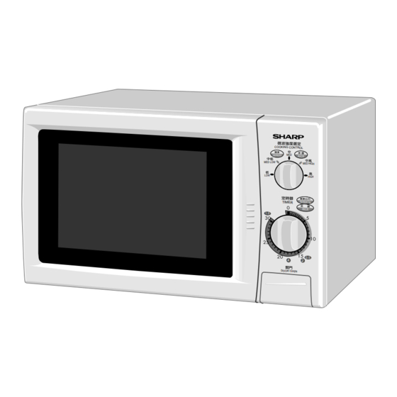
Page 5: Appearance View
R-210A APPEARANCE VIEW OVEN COOKING CONTROL DEFROST RICE MED LOW MED HIGH HIGH DEFROST kg TIMER RICE DOOR OPEN 1. Ventilation openings 6. Door seals sealing surfaces 11.Power supply cord 2. Oven lamp 7. Coupling 12.Rating label 3. Door hinges 8. -
Page 6: Operation Sequence
R-210A OPERATION SEQUENCE OFF CONDITION 7-1. When the oven door is opened during or after the cycle of a cooking program, the 1st latch switch and 1. When the timer knob is at " 0 ", the oven is OFF 2nd latch switch must open their (COM-NO) contacts condition. -
Page 7: Function Of Important Components
R-210A FUNCTION OF IMPORTANT COMPONENTS DOOR OPEN MECHANISM setting of cook time or failure of control unit. Under normal operation, the temp. fuse remains closed. However, when The door can be opened by pushing the open button on the abnormally high temperatures are reached within the control panel. -
Page 8: Servicing
Sharp recommend that wherever possible fault-finding is carried out with the supply disconnected. It may in, some cases, be necessary to connect the supply after the outer case has been removed, in this event carry out 3D checks and then disconnect the leads to the primary of the power transformer. -
Page 9: Troubleshooting Chart
R-210A TROUBLESHOOTING CHART TEST PROCEDURE A B C D E E E F F I I G G H POSSIBLE CAUSE DEFECTIVE PARTS PROBLEM CONDITION Fuse blows when power cord is plugged into wall outlet. Fuse blows when the CONDITION door is opened. -
Page 10: Test Procedure
R-210A TEST PROCEDURES PROCEDURE COMPONENT TEST LETTER MAGNETRON TEST NEVER TOUCH ANY PART IN THE CIRCUIT WITH YOUR HAND OR AN INSULATED TOOL WHILE THE OVEN IS IN OPERATION. CARRY OUT 3D CHECKS. Isolate the magnetron from the high voltage circuit by removing all leads connected to the filament terminal. - Page 11 R-210A TEST PROCEDURES PROCEDURE COMPONENT TEST LETTER Initial temperature ....................T1 = 11 C Temperature after (60 + 2) = 62 sec..............T2 = 21 C Temperature difference Cold-Warm ..............T1 = 10 C Measured output power The equation is “P = 70 x T” ............P = 70 x 10 C = 700 Watts JUDGMENT: The measured output power should be at least 15 % of the rated output power.
- Page 12 R-210A TEST PROCEDURES PROCEDURE COMPONENT TEST LETTER CAUTION: 1˚C CORRESPONDS TO 60 WATTS. REPEAT MEASUREMENT IF THE POWER IS INSUFFICIENT. (T1 C) (T2 C) (T1 C) (T2 C) Heat up for 2 min. 22 sec. POWER TRANSFORMER TEST WARNING: High voltages and large currents are present at the secondary winding and filament winding of the power transformer.
- Page 13 R-210A TEST PROCEDURES PROCEDURE COMPONENT TEST LETTER F. When the internal wire is opened in the high voltage capacitor shows an infinite resistance. G. The resistance across all the terminals and the chassis must be infinite when the capacitor is normal.
- Page 14 R-210A TEST PROCEDURES PROCEDURE COMPONENT TEST LETTER If the fuse 13A is blown by incorrect door switching replace the defective switch(es) and the fuse 13A. If the fuse 13A is blown, there is a shorts or grounds in electrical parts or wire harness.
-
Page 15: Component Replacement And Adjustment Procedure
Please refer to ‘OVEN PARTS, CABINET PARTS, CONTROL PANEL PARTS, DOOR PARTS’, when carrying out any of the following removal procedures: WARNING FOR WIRING and Oven cavity. To prevent an electric shock, take the following 3) Sharp edge: manners. Bottom plate, Oven cavity, Weveguide flange, 1. Before wiring, Chassis support and other metallic plate. - Page 16 R-210A HIGH VOLTAGE COMPONENTS REMOVAL (HIGH VOLTAGE CAPACITOR, HIGH VOLTAGE RECTIFIER ASSEMBLY AND H.V. FUSE) 9. Disconnect the H.V. fuse from high voltage capacitor. To remove the components, proceed as follows. 10.Remove the HVC cover from the high voltage capacitor.
- Page 17 Re-install oven cavity. 3. Turn the oven over. 1. Remove the any sharp edges on the turntable motor 4. Cut the four (4) bridges holding the turntable motor cover and the bottom plate with the cutting pliers. cover to the bottom plate with the cutting pliers as 2.
- Page 18 R-210A CAUTION: CAUTION: • Do not re-use the removed fan blade be- • Do not hit the fan blade strongly when installed cause the hole (for shaft) may be lager because the bracket may be transformed. than normal. • Make sure that the fan blade rotates smooth Remove the two (2) screws holding the fan motor to after installed.
- Page 19 R-210A flange of the oven front face. circuit before the door can be opened. 2. With the door closed, adjust latch hook by moving it 3. The monitor switch contacts close when the door is back and forth and up and down. In and out play of the opened.
- Page 20 R-210A ture, light or sensing of gentle warm air movement around oven door is not abnormal and do not of themselves indicate a leakage of microwave en- ergy from oven cavity. UPPER OVEN HINGE DOOR PANEL CHOKE COVER LOWER OVEN HINGE Figure C-8.
-
Page 21: Microwave Measurement
R-210A MICROWAVE MEASUREMENT Recommended instruments are: After adjustment of door latch switches, monitor switch NARDA 8100 and door are completed individually or collectively, the NARDA 8200 following leakage test must be performed with a survey HOLADAY HI 1500 instrument and it must be confirmed that the result meets... -
Page 22: Wiring Diagram
R-210A SCHEMATIC NOTE: CONDITION OF OVEN 1. DOOR CLOSED. NOTE: " " indicates components with potential above 250V. 2. TIMER KNOB AT "0" POSITION. Figure O-1 Oven Schematic-OFF Condition SCHEMATIC NOTE: CONDITION OF OVEN 1. DOOR CLOSED. 2. VARIABLE COOKING CONTROL "HIGH"... -
Page 23: Pictorial Diagram
R-210A RECTIFIER H.V. -
Page 24: Parts List
R-210A PARTS LIST Note: The parts marked " " may cause undue microwave exposure. The parts marked "*" are used in voltage more than 250V. REF. NO. PART NO. DESCRIPTION Q'TY CODE ELECTRIC PARTS 1- 1 QSWTEA126WRE0 Timer motor 30min. - Page 25 R-210A Note: The parts marked " " may cause undue microwave exposure. The parts marked "*" are used in voltage more than 250V. REF. NO. PART NO. DESCRIPTION Q'TY CODE 6-10 TLABPA032WRR0 Grounding label SCREWS,NUTS AND WASHERS 7- 1 XEPSD30P08XS0...
- Page 26 R-210A OVEN AND CABINET PARTS 4-19 1-10 1-13 4-12 4-15 1-14 4-13 6-10 7-12 4-20 4-14 7-11 4-11 1-16 7-13 4-16 7-10 1-15-1 4-17 1-15 1-11 4-10 1-12 4-18...
- Page 27 R-210A CONTROL PANEL PARTS DOOR PARTS MISCELLANEOUS Actual wire harness may be different than illustration.
- Page 28 R-210A '97SHARP CORP. (11K0.100E) Printed in Japan...
Need help?
Do you have a question about the R-210A and is the answer not in the manual?
Questions and answers