
Related Manuals for American Audio Power Amplifier V5000plus


Summary of Contents for American Audio Power Amplifier V5000plus
-
Page 1: User Instructions
Professional Power Amplifier V5000 plus AMERICAN AUDIO ® User Instructions 4295 Charter Street Los Angeles Ca. 90058 Rev. 12/03... - Page 2 Reparaturen nur von qualifizierte Fachpersonal durchführen lassen. ACHTUNG: Um einen elektrischen Schlag oder Feuergefahr zu vermeiden, sollte diesen Gerät nicht dem Regen oder Feuchtigkeit ausgesetz werden. Vor Inbetriebnahme unbedingt die Bedienungsanleitung lesen. ©American Audio® - www.americanaudio.com - V5000plus™ Power Amplifier User Manual Page 2...
-
Page 3: Table Of Contents
Subwoofer and Speaker Setup...13-14 30 Amp Plug Assembly...15 Warranty...16 Specifications...17 ©American Audio® - www.americanaudio.com - V5000plus™ Power Amplifier User Manual Page 3 FOR OPTIMUM PERFORMANCE AND RELIABILITY DO NOT PRESENT THE AMPLIFIER WITH A SPEAKER LOAD OF LESS THAN 2 OHMS OR ANY... -
Page 4: Important Precautions
C. The appliance has been exposed to rain or water. D. The fixture does not appear to operate normally or exhibits a marked change in performance. ©American Audio® - www.americanaudio.com - V5000plus™ Power Amplifier User Manual Page 4 Introduction: Congratulations and thank you for purchasing the American Audio V5000plus™... -
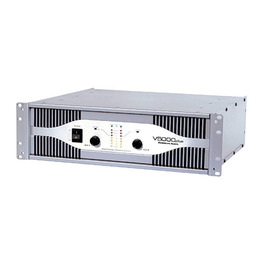
Page 5: Front Panel
When the channel goes into protect mode all output for that channel will turn off. This is to protect any ©American Audio® - www.americanaudio.com - V5000plus™ Power Amplifier User Manual Page 5 speakers connected to the channel. -
Page 6: Rear Panels
21. Reset Button - This button is used to reset the breaker. 22. AC Cord - Plug this cable into a standard 110~120v wall outlet. ©American Audio® - www.americanaudio.com - V5000plus™ Power Amplifier User Manual Page 6 29 28 27 26 25 24 Check that the voltage in your area matches the amplifiers required volt- age. -
Page 7: Inputs
Insert the banana jacks into the caps of the binding post, be sure that the banana jack is inserted securely to avoid the risk of it popping out. ©American Audio® - www.americanaudio.com - V5000plus™ Power Amplifier User Manual Page 7... - Page 8 Spade Connector: (Diagram 8) When connecting your speakers to the amplifier using spade connector; Unscrew the red and black caps on the binding post, be sure not to completely remove or unscrew the red and black caps. Insert the spade con- nector in to the binding post and tighten the caps down on the spade connector.
-
Page 9: Speakon Output Connector Assembly
7. Slide the coupler (E) along the cable and screw it onto the end of the housing (A). Before tightening, you may want to test the connector to make sure it has been assembled properly. ©American Audio® - www.americanaudio.com - V5000plus™ Power Amplifier User Manual Page 9 NL4FC Diagram 9 ®... -
Page 10: Operating Modes
Frequencies may be adjusted from 20Hz to 200Hz. Page 13/ Diagram 14 details a typical Stereo Subwoofer set up. ©American Audio® - www.americanaudio.com - V5000plus™ Power Amplifier User Manual Page 10... -
Page 11: Limiter
"Clip" LED and “Protect" LED will light simultaneously indicating amplifier fault. All channel output during the “Short Circuit Protection" will be interrupted (i.e. no sound out ©American Audio® - www.americanaudio.com - V5000plus™ Power Amplifier User Manual Page 11... -
Page 12: Thermal Protection
LED indicates signal clipping. One red LED indicates protections mode for shorts/ overload. Both channels will also share the center green LED that indicate the amplifier operating mode. FUNCTION INDICATORS - These green LED indicators detail the amplifiers current operating mode (Stereo, Mono, or Bridge). ©American Audio® - www.americanaudio.com - V5000plus™ Power Amplifier User Manual Page 12... -
Page 13: Subwoofer And Speaker Setup
Negative (-) Lead Use the two red terminal from the banana jacks to Use either the Speakon or the banana jacks power a subwoofer speaker in mono-bridge mode. ©American Audio® - www.americanaudio.com - V5000plus™ Power Amplifier User Manual Page 13... -
Page 14: Typical Stereo Output Connections
Use Channel 1 Inputs Only (XLR or 1/4” Jacks) Use the two positive binding post termainals (red) for speaker output. ©American Audio® - www.americanaudio.com - V5000plus™ Power Amplifier User Manual Page 14 TYPICAL STEREO OUTPUT CONNECTIONS Use Speakon or Banana Jacks... -
Page 15: Amp Plug Assembly
9. Reassemble, the 30 amp plug by replacing the three (3) phillips screws on the top of the plug and the two (2) at the base to close the plug. Diagram 17 ©American Audio® - www.americanaudio.com - V5000plus™ Power Amplifier User Manual Page 15 Diagram 18... -
Page 16: Warranty
C. This warranty is void if the serial number has been altered or removed; if the product is modified in any manner which American Audio® con- cludes, after inspection, affects the reliability of the product; if the product has been repaired or serviced by anyone other than the American Audio®... -
Page 17: Specifications
8 ohms 5A @ 120v AC Cooling System: 1 Dual Speed Fan and Heatsinks American Audio® - www.americanaudio.com - V5000plus™ Power Amplifier User Manual Page 17 V-1500 V-2000 PLUS 650w RMS Per Ch. 280w RMS Per Ch. - Page 18 ©American Audio® American Audio® is part of the American DJ® Group of Companies American DJ® World Headquarters: 4295 Charter Street Los Angeles, CA 90058 USA Tel: 323-582-2650 / Fax: 323-582-2610 web: www.americanaudio.com / e-mail: info@americanaudio.com...
Need help?
Do you have a question about the Power Amplifier V5000plus and is the answer not in the manual?
Questions and answers