
Subscribe to Our Youtube Channel
Related Manuals for Avital AviStar 3300


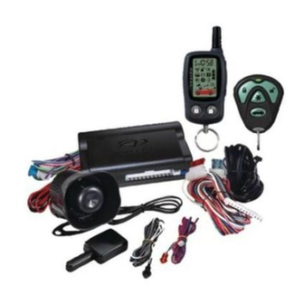
Summary of Contents for Avital AviStar 3300
- Page 1 ® AviStart 3300 Installation Guide NEW! HF Plus Receiver for Extended Range © 2001 Directed Electronics, Inc. Vista, CA N3300 8-01 Rev. A 1.1...
-
Page 2: Table Of Contents
1.4 or newer to program this unit. Avital®, Bitwriter™, Code Hopping™, DEI®, Doubleguard®, ESP™, FailSafe®, Ghost Switch™, Learn Routine™, Nite-Lite®, Nuisance Prevention Circuitry®, NPC®, Revenger®, Silent Mode™, Soft Chirp®, Stealth Coding™ Technology, Stinger®, Valet®, Vehicle Recovery System®, VRS®, and Warn Away®... -
Page 3: Wiring Quick Reference Guide
wiring quick reference guide © 2000 Directed Electronics, Inc. Vista, CA... -
Page 4: Warning! Safety First
warning! safety first The following safety warnings must be observed at all times: I Due to the complexity of this system, installation of this product must only be performed by an authorized DEI dealer. I When properly installed, this system can start the vehicle via a command signal from the remote control transmitter. -
Page 5: Installation Points To Remember
installation points to remember before beginning the installation IMPORTANT! This product is designed for fuel-injected, automatic transmission vehicles only. Installing it in a standard transmission vehicle is dangerous and is contrary to its intended use. I Please read this entire installation guide before beginning the installation. The installation of this remote start system requires interfacing with many of the vehicle’s systems. -
Page 6: Finding The Wait-To-Start Bulb Wire For Diesels
finding the wait-to-start bulb wire for diesels In diesel vehicles it is necessary to interface with the wire that turns on the WAIT TO START light in the dash- board. This wire illuminates the bulb until the vehicle’s glow plugs are properly heated. When the light goes out the vehicle can be started. -
Page 7: Primary Harness (H1), 12-Pin Connector
primary harness (H1), 12-pin connector ______ ORANGE (-) 500 mA ARMED OUTPUT H1/1 ______ WHITE (+)/(-) SELECTABLE LIGHT FLASH OUTPUT H1/2 ______ WHITE/BLUE (-) REMOTE START ACTIVATION INPUT H1/3 ______ BLACK/WHITE (-) 200 A DOMELIGHT SUPERVISION OUTPUT H1/4 ______ H1/5 GREEN (-) DOOR TRIGGER INPUT, ZONE 3 ______... -
Page 8: Remote Start Primary Harness, 5-Pin Connector
remote start primary harness, 5-pin connector ______ PURPLE (-) 200 mA STARTER RELAY TURN-ON ______ ORANGE (-) 200 mA ACCESSORY RELAY TURN-ON ______ PINK (-) 200 mA IGNITION RELAY TURN-ON ______ YELLOW (+) IGNITION INPUT TO ALARM ______ (+) CONSTANT POWER heavy gauge relay satellite key switch interface ______ (+) HIGH CURRENT 12V INPUT... -
Page 9: Primary Harness (H1) Wire Connection Guide
primary harness (H1) wire connection guide H1/1 ORANGE (-) ground-when-armed output This wire supplies a (-)500 mA ground as long as the system is armed. This output ceases as soon as the system is disarmed. The orange wire is pre-wired to control the DEI ®... - Page 10 (-) Light Flash Output NOTE: For parking light circuits that draw 10 amps or more, the jumper must be switched to a (-) light flash output. (See the Programming Jumpers section of this guide.) P/N 8617 or a standard automotive SPDT relay must be used on the H1/2 light flash output harness wire. H1/3 WHITE/BLUE remote start (-) activation input A momentary input on this wire will start or stop the motor, just as transmitting Channel 3 from the remote trans- mitter does.
- Page 11 H1/5 GREEN (-) door trigger input, zone 3 Most vehicles use negative door trigger circuits. Connect the green wire to a wire which shows ground when any door is opened. In vehicles with factory delays on the domelight circuit, there is usually a wire that is unaffected by the delay circuitry.
- Page 12 H1/10 BROWN (+) siren output Connect this to the red wire of the siren. Connect the black wire of the siren to (-) chassis ground, preferably at the same point you connected the control module’s black ground wire. H1/11 RED (+)12V constant power input Before connecting this wire, remove the supplied fuse.
-
Page 13: Secondary Harness (H2) Wire Connection Guide
secondary harness (H2) wire connection guide H2/1 VIOLET/BLACK 200 mA (-) channel 4 output This wire provides a (-) 200mA output whenever the transmitter button(s) controlling Channel 4 is pressed. This output can be programmed to provide the following types of outputs (see also the Feature Menus section): I Validity: Output that will send a signal as long as the transmission is received. - Page 14 H2/3 GRAY/BLACK (-) diesel wait-to-start bulb input Connect this wire to the wire in the vehicle that sends the signal to turn on the WAIT-TO-START bulb in the dash- board. In most diesels the wire is negative (ground turns on the bulb) and the GRAY/BLACK wire can be directly connected to the wire in the vehicle.
-
Page 15: Relay Satellite Key Switch Interface Wire Connection Guide
relay satellite key switch interface wire connection guide The five heavy gauge wires coming from the relay satellite are used to energize high current circuits in the vehicle. It is crucial that these connections are well-made and capable of handling the current demands. For this reason, Scotch-Locks, T-taps and other such connectors are strongly discouraged. -
Page 16: Wire Connection Guide
remote start secondary harness (H3) wire connection guide H3/1 BLUE (-) status/factory re-arm output This wire supplies a 200mA output as soon as the module begins the remote start process. It can be used to control an immobilizer bypass module for vehicles with factory immobilizers. The H3/1 BLUE wire can also be used to rearm a factory anti-theft system when the remote start shuts down. -
Page 17: Neutral Safety Switch Interface
systems locating a proper signal may be more difficult. Once connected, you must teach the system the tach signal. (See the Programming Jumpers section of this guide.) H3/6 BLACK/WHITE neutral safety switch input Connect this wire to the provided toggle (override) switch as shown in figure A. Connect the other wire from the toggle switch to the PARK/NEUTRAL switch in the vehicle. -
Page 18: Testing The Neutral Safety Switch
According to available information, the only vehicles currently manufactured this way are most General Motors trucks, sport utility vehicles and column shifting passenger cars. Available information also indicates that pre- 1996 Dodge Dakota pickups with 2.5 liter motors are manufactured this way as well. GM vehicles that have the neutral safety switch built into the column shifter can usually be identified by a purple starter wire. - Page 19 In addition, you must connect a tan (+) shut-down input to the yellow wire on the relay satellite ribbon cable. This prevents the remote start system from activating if the key is left in the "run" position. If your remote start system only has one tan input, you must use diodes to isolate the ignition circuit from the brake switch input.
-
Page 20: Bypassing Gm Vehicle Anti-Theft Systems (Vats)
bypassing GM vehicle anti-theft systems (VATS) Vehicles with the GM VATS (Pass Key) systems have a resistor embedded in the ignition key. If the VATS decoder module does not measure the proper resistance when the vehicle is started, the starter and fuel pump may be disabled for up to ten minutes. -
Page 21: 1995 And Newer Vehicle Anti-Theft Systems (Immobilizers)
1995 and newer vehicle anti-theft systems (immobilizers) 1995 and newer vehicle anti-theft systems (immobilizers) require a bypass module. The bypass module allows for easy interfacing, while still maintaining the OEM system’s integrity. passlock I and passlock II (PL-1 and PL-2) The Passlock I and Passlock II systems can be found in the following General Motors vehicles: I ‘95 and newer Cavalier and Sunfire I ‘96 and newer Achieva, Grand Am, and Skylark... -
Page 22: Plug-In Led And Valet/Program Switch
will excite the transponder, which is located (but not visible) in the head of the ignition key. The key transpon- der will then send a unique code back to the transceiver for evaluation. If the code matches a valid code of the system, the vehicle will be allowed to start. -
Page 23: Shock Sensor Harness, 4-Pin Connector
shock sensor harness, 4-pin connector GREEN (-) multiplex input, zone 2 Inputs shorter than 0.8 seconds will trigger the Warn Away response, while inputs longer than 0.8 seconds will trigger full alarm sequence and report Zone Two. If installing an optional DEI dual stage sensor, connect to the green wire as shown in the following. -
Page 24: Tach Learning
tach learning To learn the tach signal: Start the vehicle with the key. DRW-96 Within 5 seconds, press and HOLD the Valet®/Program switch. The LED will light constant when the tach signal is learned. Release the Valet®/Program switch. door lock harness (H4) wire connection guide ______ H4/A GREEN... -
Page 25: Positive-Triggered, Relay Driven Systems (Type A)
type A: (+) 12V pulses from the switch to the factory relays The system can control Type A door locks directly, with no additional parts. The switch will have three wires on it, and one will test (+)12V constantly. The others will alternately pulse (+)12V when the switch is pressed to the lock or unlock position. -
Page 26: Negative-Triggered, Relay Driven Systems (Type B)
type B: (-) pulses from the switch to the factory relays This system is common in many Toyotas, Nissans, Hondas, and Saturns, as well as Fords with the keyless-entry system (some other Fords also use Type B). The switch will have three wires on it, and one wire will test ground all the time. One wire will pulse (-) when the switch locks the doors, and the other wire will pulse (-) when the switch unlocks the doors. -
Page 27: Actuators (Type D)
Type C: Reversing Polarity, cont. type D: after-market actuators In order for this system to control one or more after-market actuators, a DEI 451M or two relays (optional) are needed. Vehicles without factory power door locks require the installation of one actuator per door. This requires mounting the door lock actuator inside the door. -
Page 28: Electrically Activated Vacuum (Type E)
type E: mercedes-benz and audi (1985 & newer) Type E door locks are controlled by an electrically activated vacuum pump. Some Mercedes and Audis use a Type D system. Test by locking doors from the passenger key cylinder. If all the doors lock, the vehicle's door lock system can be controlled with just two relays or a DEI 451M. -
Page 29: Type G: Positive (+) Multiplex
type G: positive (+) multiplex This system is most commonly found in Ford, Mazda, Chrysler and GM vehicles. The door lock switch or door key cylinder may contain either one or two resistors. When interfacing with this type of door lock system, two relays or a DEI 451M must be used. -
Page 30: Type H: Negative (-) Multiplex
type H: negative (-) multiplex The system is most commonly found in Ford, Mazda, Chrysler and GM vehicles. The door lock switch or door key cylinder may contain either one or two resistors. single-resistor type If one resistor is used in the door lock switch/key cylinder, the wire will pulse ground in one direction and resist- ance to ground when operated in the opposite direction. -
Page 31: Programming Jumpers
programming jumpers jumper 1: tach threshold on/off In most cases, this jumper can be left in the default OFF position. Some new vehicles use less than 12 volts in their ignition systems. The unit may have trouble learning the tach signal in these vehicles. Changing the jumper to the ON setting changes the trigger threshold of the digital tach circuit so it will work properly with these vehi- cles. -
Page 32: Transmitter/Receiver Learn Routine
transmitter/receiver learn routine The system comes with two transmitters that have been taught to the receiver. The receiver can store up to four different transmitter codes in memory. Use the following learn routine to add transmitters to the system or to change button assignments. - Page 33 *NOTE: For Auto Learn Configurations, see Transmitter Configurations section of this guide. **NOTE: If any transmitter button from a known transmitter is programmed to Channel 10, all transmitters will be erased from memory and will revert to the default feature settings. (See Features Menu section of this guide.) This is useful in cases where one of the customer's transmit- ters is lost or stolen.
-
Page 34: Transmitter Configurations
transmitter configurations The transmitters can be programmed with the standard or single button arm/disarm configurations by using the Auto Learn functions in the Transmitter/Receiver Learn Routine. standard configuration A remote that uses the standard configuration operates similarly to many factory keyless entry remotes. A stan- dard configuration transmitter allows arming, disarming, and Panic Mode activation with separate buttons. -
Page 35: Multi-Level Security Arming
multi-level security arming Multi-Level Security Arming is a feature that allows the user to select which of the system's inputs or sensors will be active and which will be bypassed when the system is armed. (See Table of Zones section of this guide.) Multi-Level Security Arming can only be accessed from a standard configuration transmitter. -
Page 36: Operating Settings Learn Routine
system features learn routine The System Features Learn Routine dictates how the unit operates. It is possible to access and change any of the feature settings using the Valet/program switch. However, this process can be greatly simplified by using the optional Personal Computer Interface or Bitwriter (p/n 998T). - Page 37 NOTE: Some features have more than two possible settings. Pressing Channel One will select the one chirp setting, pressing Channel Two will toggle through the two-chirp and higher settings.) Release. Release the Valet/Program switch. Once a feature is programmed: Other features can be programmed within the same menu. Another menu can be selected.
-
Page 38: Feature Menus
feature menus The default settings are indicated in bold type. Features that have additional settings that can be programmed using the Bitwriter are indicated with an asterisk (*). menu #1 - basic features FEATURE NUMBER ONE-CHIRP SETTING (DEFAULT) TWO-CHIRP SETTING Active arming Passive arming Arm/disarm chirps on... -
Page 39: Feature Descriptions
menu #3 - remote start options FEATURE ONE-CHIRP SETTING (DEFAULT) TWO-CHIRP SETTING Engine checking on Engine checking OFF Engine checking TACH Engine checking VOLTAGE Run time: 12 minutes* Run time: 24 or 60 minutes* Parking lights flashing Parking lights constant Crank time 0.6 seconds 0.8, 1.0, 1.2, 1.6, 1.8, 2.0, 4.0 Voltage check - high... -
Page 40: Menu #2
NOTE: Remember, when passive arming is selected, the unit will chirp 20 seconds after the last door is closed. The system does not actually arm or lock the doors until 30 seconds after the door has been closed. 1-5 PANIC WITH IGNITION ON: This feature controls whether or not the panic mode is available with the igni- tion on. - Page 41 2-2 SIREN DURATION 30/60 SECONDS: It is possible to program the unit to sound for 30 or 60 seconds during the triggered sequence. Some states have laws regulating how long a security system can sound. When using the TechSoft Programmer or Bitwriter™, the siren can be programmed to sound for any length of time from 1 second to 180 seconds.
-
Page 42: Menu #3
2-8 DOUBLE PULSE UNLOCK ON/OFF: Some vehicles require two pulses on a single wire to unlock the doors. When the double pulse unlock feature is turned on, the BLUE H4/C wire will supply two negative pulses instead of a single pulse. At the same time, the GREEN H4/A wire will supply two positive pulses instead of a single pulse. This makes it possible to directly interface with double pulse vehicles without any extra parts. -
Page 43: Nuisance Prevention Circuitry
3-6 VOLTAGE CHECK HI/LOW: This feature only functions when programmed for voltage sense. Some vehicles have many accessories, which are turned on when remote started. In these vehicles, the variation of voltage between the engine off and the car running is very small and the remote start unit may "think" the vehicle has not started. -
Page 44: Valet Mode
valet mode To enter or exit valet mode with the valet/program switch: Turn the ignition key on and then off. At any time during the next 10 seconds, press and release the Valet switch. Now the Status LED will light constantly if you have entered Valet Mode or go out if you have exited Valet Mode. -
Page 45: Table Of Zones
When entering Timer Mode, the engine should shut down. The parking lights (if connected) will flash four times and the engine will restart. The system is in Timer Mode. The engine may be allowed to run for its programmed run time, or the transmitter can be used to shut down the engine. Either way, the remote start system will restart the engine again in three hours. -
Page 46: Shutdown Diagnostics
shutdown diagnostics To perform shutdown diagnostics: 1. With the ignition OFF, press and hold the Valet/Program button. 2. Turn the ignition ON and then back OFF while holding the Valet/Program button. 3. Release the Valet/Program button. 4. Press and release the Valet/Program button. The LED will report the last shutdown for one minute or until the ignition is turned on. -
Page 47: Long Term Event History
long term event history The system stores the last two full triggers in memory. These are not erasable. Each time the unit sees a full trigger, the older of the two triggers in memory will be replaced by the new trigger. To access long term event history: With the ignition off, press and HOLD the Valet®/Program switch. -
Page 48: Troubleshooting
3. Test the NEUTRAL SAFETY shutdown circuit: IMPORTANT! Make sure there is adequate clearance to the front and rear of the vehicle before attempting this test. a. Make sure the hood is closed and no other shutdown circuits are active. b. -
Page 49: Remote Start Troubleshooting
I Closing the door triggers the system, but opening the door does not: Have you correctly identified the type of door switch system? This happens often when the wrong door input has been used. (See Door Lock Harness Wire Connection Guide section of this guide.) I System will not passively arm until it is remotely armed and then disarmed: Are the door inputs connected? Is the H1/6 blue wire connected to the door trigger wire in the vehicle? Either the H1/5 green or the H1/7 violet should be used instead. - Page 50 6. Check connections. The two red heavy gauge input wires on the relay satellite should have solid connections. "T-taps" or "scotch locks" are not recommended for any high current heavy gauge wiring. Also, if the vehicle has more than one 12-volt input wire, then connect one red wire to each. I The vehicle starts, but immediately dies.
Need help?
Do you have a question about the AviStar 3300 and is the answer not in the manual?
Questions and answers