Table of Contents
Advertisement
[1]
Important Service Safety Precaution ........... 1-1
[2]
Specifications............................................... 1-1
[3]
Names Of Parts ........................................... 1-2
[1]
Cd Section .................................................. 2-1
[2]
Test Mode .................................................... 2-2
[3]
Standard Specification Of Stereo System
Error Message Display Contents ................. 2-4
[1]
..................................................................... 3-1
[2]
Disassembly ................................................ 3-2
CHAPTER 4. BLOCK DIAGRAM
[1]
Block Diagram ............................................. 4-1
" are important for maintaining the safety of the set. Be sure to replace these parts with
!
specified ones for maintaining the safety and performance of the set.
SHARP CORPORATION
SERVICE MANUAL
MICRO COMPONENT SYSTEM
MODEL
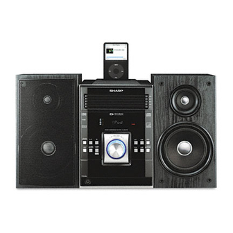
XL-DK225 Micro Component System consisting of
XL-DK225 (main unit) and CP-DK225 (speaker system).
• In the interests of user-safety (Required by safety regulations in
some countries) the set should be restored to its original condition
and only parts identical to those specified be used.
CONTENTS
CHAPTER 5. CIRCUIT DESCRIPTION
[1]
Waveforms Of Servo Circuit ........................ 5-1
[2]
IC Voltage .................................................... 5-3
LAYOUT
[1]
Notes On Schematic Diagram ..................... 6-1
[2]
Types Of Transistor And Led ...................... 6-1
[3]
Schematic Diagram ..................................... 6-2
[4]
Charts Of Connecting Wires ...................... 6-10
[5]
Wiring Side of PWB ................................... 6-12
[1]
Troubleshooting ........................................... 7-1
[1]
Function Table Of IC .................................... 8-1
[2]
Fl Display.................................................... 8-9
PARTS GUIDE
This document has been published to be used for
after sales service only.
– 1
The contents are subject to change without notice.
XL-DK225
No. S7734XLDK225/
XL-DK225
Advertisement
Table of Contents

Related Manuals for Sharp XL-DK225


Summary of Contents for Sharp XL-DK225
- Page 1 XL-DK225 MODEL XL-DK225 Micro Component System consisting of XL-DK225 (main unit) and CP-DK225 (speaker system). • In the interests of user-safety (Required by safety regulations in some countries) the set should be restored to its original condition and only parts identical to those specified be used.
- Page 2 XL-DK225 Audio XL-MP150 Service Manual XLMP150 Market PRECAUTIONS FOR USING LEAD-FREE SOLDER 1. Employing lead-free solder "MAIN, POWER, SPEAKER, TRANSIT iPOD, DISPLAY, HEADPHONE, RE-FLASH, VOLUME LED, iPOD, CD MP3 PWB" of this model employs lead-free solder. The LF symbol indicates lead-free solder, and is attached on the PWB and service manuals. The alphabetical character following LF shows the type of lead-free solder.
-
Page 3: Important Service Safety Precaution
XL-DK225 CHAPTER 1. GENERAL DESCRIPTION [1] Important Service Safety Precaution CAUTION : “These servicing instructions are for use by qualified service personnel only. To reduce the risk of electric shock do not perform any servicing other than that contained in the operating instructions unless you are qualified to do so”. -
Page 4: Names Of Parts
XL-DK225 [3] Names Of Parts Front panel 1. iPod Terminal 2. Disc Trays 3. Timer Indicator 4. Remote Sensor 5. Disc Stop Button 6. Disc or iPod Play or Pause Button 7. Power On/Standby Button 8. CD Button 9. Tuner (Band) Button 10. - Page 5 XL-DK225 Remote control 1. Remote Control Transmitter 2. Disc Number Select Buttons 3. Disc Direct Search Buttons 4. Equalizer Mode Select Button 5. Extra Bass/Demo Button 6. Volume Up and Down Buttons 7. Power On/Stand-by Button 8. CD Button 9. Tuner (Band) Button 10.
- Page 6 XL-DK225 CHAPTER 2. ADJUSTMENTS [1] CD Section 1. CD SECTION • Adjustment Since this CD system incorporates the following automatic adjustment functions, readjustment is not needed when replacing the pickup. Therefore, different PWBs and pickups can be combined freely. Each time a disc is changed, these adjustments are performed automatically.
-
Page 7: Test Mode
XL-DK225 [2] Test Mode • Setting the test mode During stand-by mode, press STOP button while pressing down the button and button. Then, press the CD button to enter the test mode. T E S T IL isn’t done OPEN/CLOSE operation is using manual. - Page 8 XL-DK225 STOP and return to Step 1 Everytime << DISPLAY >> key input a) Focus Balance = FB : XX b) Focus Gain = FG : XX c) Tracking Balance = TB : XX d) Tracking Gain = TG : XX...
-
Page 9: Standard Specification Of Stereo System Error Message Display Contents
XL-DK225 [3] Standard Specification Of Stereo System Error Message Display Contents Error Contents DISPLAY Notes CD Changer Mechanism Error. ‘ER-CD**’ (*) 10: CAM SW Detection NG during normal operation 11: CAM SW Detection NG during initialize process 20: TRAY SW Detection NG during normal operation 21: TRAY SW Detection NG during initialize process Focus Not Match/IL Time Over. - Page 10 XL-DK255 CHAPTER 3. MECHANICAL DESCRIPTION [1] Removing And Reinstalling The Main Parts Reduction gear D 1. CHANGER MECHANISM SECTION Perform steps 1, 2, 9 and 10 of the disassembly method to remove the CD changer mechanism. 1.1 How to remove CD Disc (See Fig. 1-4) 1.
-
Page 11: Figure
XL-DK255 [2] Disassembly Caution on disassembly Top Cabinet Front Panel Follow the below-mentioned notes when disassembling the unit and reassembling it, to keep it safe and ensure excellent performance: 1) Take cassette tape and compact disc out of the unit. (A1)x2 2) Be sure to remove the power supply plug from the 3x12mm... - Page 12 XL-DK255 Rear Panel (P2)x4 Special (H1)x2 CD Mechanism Ø3x10mm CD Changer Unit Speaker PWB Figure 4 Front Panel Display PWB (J2)x1 (J4)x6 Figure 8 Ø 2.6x10mm (J1)x1 (J3)x1 STEP PROCEDURE FIGURE REMOVAL Woofer 1. Net Frame Ass’y.... (A1) X 1 9, 10 SUB PWB 2.
- Page 13 XL-DK255 -MEMO- 3 – 4...
- Page 14 XL-DK225 CHAPTER 4. DIAGRAMS [1] Main Block Diagram Figure 4-1: MAIN BLOCK DIAGRAM (1/2) 4 – 1...
- Page 15 XL-DK225 Figure 4-2: MAIN BLOCK DIAGRAM (2/2) 4 – 2...
- Page 16 XL-DK225 [2] CD Block Diagram Figure 4-3: CD BLOCK DIAGRAM (1/2) 4 – 3...
- Page 17 XL-DK225 Figure 4-4: CD BLOCK DIAGRAM (2/2) 4 – 4...
- Page 18 XL-DK225 CHAPTER 5. CIRCUIT DESCRIPTION [1] Waveforms Of CD Circuit SPDO PDOUT 0 PDOUT 1 RFOUT RFOUT 5 – 1...
- Page 19 XL-DK225 [2] Voltage VOLTAGE VOLTAGE VOLTAGE VOLTAGE 0.02 0.01 1.53 3.26 1.63 1.52 0.03 1.63 0.76 3.03 3.27 0.98 1.52 0.03 0.02 0.70 0.59 1.52 0.03 1.74 0.01 3.27 1.63 0.70 1.63 3.27 1.53 1.63 3.27 0.03 3.27 1.68 1.63 4.53...
- Page 20 XL-DK225 IC701 IC702 VOLTAGE VOLTAGE VOLTAGE VOLTAGE 3.22 3.30 -26.44 -26.42 3.22 3.14 -26.40 -28.77 0.00 3.31 -26.40 -26.41 0.00 3.31 -26.40 -26.40 0.00 3.15 3.24 -26.41 3.22 3.23 3.20 -24.06 0.00 3.24 3.24 -17.00 0.00 3.23 3.24 -26.40 0.00 3.24...
- Page 21 XL-DK225 IC703 IC705 IC901 VOLTAGE VOLTAGE VOLTAGE VOLTAGE 3.30 3.90 -0.10 -23.00 3.30 0.60 -0.10 0.00 0.00 5.60 0.00 21.90 -22.10 -20.70 0.00 0.00 -0.10 0.00 -0.10 23.10 IC852 IC853 IC851 VOLTAGE VOLTAGE VOLTAGE VOLTAGE 15.80 3.30 5.10 16.20 0.00 0.00...
- Page 22 XL-DK225 -MEMO- 5 – 5...
-
Page 23: Layout 1] Notes On Schematic Diagram
XL-DK225 CHAPTER 6. CIRCUIT SCHEMATICS AND PARTS LAYOUT [1] Notes On Schematic Diagram • Resistor: • Schematic diagram and Wiring Side of P.W.Board To differentiate the units of resistors, such symbol as this model subject change K and M are used: the symbol K means 1000 ohm improvement without prior notice. -
Page 24: Schematic Diagram
XL-DK225 [3] Schematic Diagram Figure 6-1: MAIN SCHEMATIC DIAGRAM (1/2) 6 – 2... - Page 25 XL-DK225 Figure 6-2: MAIN SCHEMATIC DIAGRAM (2/2) 6 – 3...
- Page 26 XL-DK225 Figure 6-3: POWER SCHEMATIC DIAGRAM (1/2) 6 – 4...
- Page 27 XL-DK225 SPEAKER JACK PWB Figure 6-4: POWER SCHEMATIC DIAGRAM (2/2) 6 – 5...
- Page 28 XL-DK225 SYSTEM MICOM REFLASH PWB Figure 6-5: DISPLAY SCHEMATIC DIAGRAM (1/2) 6 – 6...
- Page 29 XL-DK225 Figure 6-6: DISPLAY SCHEMATIC DIAGRAM (2/2) 6 – 7...
- Page 30 XL-DK225 Figure 6-7: CD MP3 SCHEMATIC DIAGRAM (1/2) 6 – 8...
- Page 31 XL-DK225 Figure 6-8: CD MP3 SCHEMATIC DIAGRAM (2/2) 6 – 9...
- Page 32 XL-DK225 RESISTOR WITH 1% TOLERANCE IPOD CONNECTION Figure 6-9: iPOD SCHEMATIC DIAGRAM (1/2) 6 – 10...
- Page 33 XL-DK225 TO TRANSIT iPOD Figure 6-10: iPOD SCHEMATIC DIAGRAM (2/2) 6 – 11...
-
Page 34: Charts Of Connecting Wires
XL-DK225 [4] Charts Of Connecting Wires FFC301 TRANSIT iPOD TUNER PACK PWB-A4 ANTENNA 2 4 6 8 10 12 CNPU4 1 3 5 7 9 11 CNPU5 1 2 3 4 5 6 7 8 9 10 11 12 1 2 3 4 5 6 7 8 9 10 11 12... - Page 35 XL-DK225 FROM DISPLAY PWB-B1 CNP702 2 4 6 8 10 9 7 5 3 1 1 3 5 7 9 8 6 4 2 CNP5 CNP6 CNP3 CD MP3 PWB-C CNP1 2 4 6 8 10 FROM 3 5 7 9...
-
Page 36: Wiring Side Of Pwb
XL-DK225 [5] Wiring Side Of PWB SPEAKER PWB-A3 R-CH L-CH MAIN PWB-A1 R-CH L-CH Lead-free solder indication Lead-free solder is used in the MAIN PWB. Refer to "Precautions for handling lead-free solder" for instructions and precautions. Figure 6-13: WIRING SIDE OF MAIN PWB (TOP VIEW) (1/2) - Page 37 XL-DK225 TRANSIT iPOD PWB-A4 2 3 4 5 6 7 8 9 10 11 12 8 1012 7 9 11 VIDEO/AUX IN L-CH and R-CH VIDEO OUT 1 2 3 4 5 6 7 8 9 10 11121314 15 SUBWOOFER...
- Page 38 XL-DK225 MAIN PWB-A1 Lead-free solder indication Lead-free solder is used in the MAIN PWB. Refer to "Precautions for handling lead-free solder" for instructions and precautions. Figure 6-15: WIRING SIDE OF MAIN PWB (BOTTOM VIEW) (1/2) 6 – 16...
- Page 39 XL-DK225 Figure 6-16: WIRING SIDE OF MAIN PWB (BOTTOM VIEW) (2/2) 6 – 17...
- Page 40 XL-DK225 POWER PWB-A2 T.F. POWER SUPPLY 9 10 11 12 13 14 15 16 17 AC 120V~60Hz B C E Lead-free solder indication COLOR TABLE Lead-free solder is used in the POWER PWB. WHITE Refer to "Precautions for handling lead-free solder"...
- Page 41 XL-DK225 -MEMO- 6 – 19...
- Page 42 XL-DK225 DISPLAY PWB-B1 8 10 12 14 16 9 11 13 15 17 Lead-free solder indication Lead-free solder is used in the DISPLAY PWB. Refer to "Precautions for handling lead-free solder" for instructions and precautions. Figure 6-18: WIRING SIDE OF DISPLAY PWB (TOP VIEW) (1/2)
- Page 43 XL-DK225 4 5 6 7 8 9 1 2 3 8 10 12 1 2 3 4 5 6 7 Figure 6-19: WIRING SIDE OF DISPLAY PWB (TOP VIEW) (2/2) 6 – 21...
- Page 44 XL-DK225 DISPLAY PWB-B1 2 3 4 5 6 7 8 9 19 20 21 22 23 24 25 26 27 2 Lead-free solder indication Lead-free solder is used in the DISPLAY PWB. Refer to "Precautions for handling lead-free solder" for instructions and precautions.
- Page 45 XL-DK225 24 25 26 27 28 29 30 31 32 33 34 35 36 37 38 39 40 41 42 43 44 45 46 47 48 49 50 51 Figure 6-21: WIRING SIDE OF DISPLAY PWB (BOTTOM VIEW) (2/2) 6 – 23...
- Page 46 XL-DK225 HEADPHONE PWB-B2 1 2 3 4 5 FROM HEADPHONE REFLASH PWB-B3 VOLUME LED PWB-B4 Lead-free solder indication Lead-free solder is used in the HEADPHONE, REFLASH, VOLUME LED PWB. Refer to "Precautions for handling lead-free solder" for instructions and precautions.
- Page 47 XL-DK225 HEADPHONE PWB-B2 VOLUME LED PWB-B4 Lead-free solder indication Lead-free solder is used in the HEADPHONE, VOLUME LED PWB. Refer to "Precautions for handling lead-free solder" for instructions and precautions. Figure 6-23: WIRING SIDE OF HEADPHONE, VOLUME LED PWB (BOTTOM VIEW)
- Page 48 XL-DK225 iPOD PWB-C Lead-free solder indication Lead-free solder is used in the iPOD PWB. Refer to "Precautions for handling lead-free solder" for instructions and precautions. Figure 6-24: WIRING SIDE OF iPOD PWB (TOP VIEW) 6 – 26...
- Page 49 XL-DK225 iPOD PWB-C Lead-free solder indication Lead-free solder is used in the iPOD PWB. Refer to "Precautions for handling lead-free solder" for instructions and precautions. Figure 6-25: WIRING SIDE OF iPOD PWB (BOTTOM VIEW) 6 – 27...
- Page 50 XL-DK225 CD MP3 PWB-D 5 4 3 SCREW TO CHASSIS 2 4 6 8 1 3 5 7 11 13 Figure 6-26: WIRING SIDE OF CD MP3 PWB (TOP VIEW) (1/2) 6 – 28...
- Page 51 XL-DK225 12 14 12 14 16 11 13 15 Lead-free solder indication Lead-free solder is used in the CD MP3 PWB. Refer to "Precautions for handling lead-free solder" for instructions and precautions. Figure 6-27: WIRING SIDE OF CD MP3 PWB (TOP VIEW) (2/2)
- Page 52 XL-DK225 CD MP3 PWB-D Lead-free solder indication Lead-free solder is used in the CD MP3 PWB. Refer to "Precautions for handling lead-free solder" for instructions and precautions. Figure 6-28: WIRING SIDE OF CD MP3 PWB (BOTTOM VIEW) (1/2) 6 – 30...
- Page 53 XL-DK225 Figure 6-29: WIRING SIDE OF CD MP3 PWB (BOTTOM VIEW) (2/2) 6 – 31...
- Page 54 XL-DK225 CHAPTER 7. FLOWCHART [1] Troubleshooting 1. When the CD does not function The CD section may not operate when the objective lens of the optical pickup is dirty. Clean the objective lens, and check the playback operation. When this section does not operate even after the above step is taken, check the following items.
- Page 55 XL-DK225 (1) Focus-RF system check. Although a CD is inserted and the cover is closed, "NO DISC" is displayed. Press the Tray1 CD Eject Button without inserting a disc, and try starting the playback operation. Figure 1 1. Does the pickup move to the PICKUP-IN Switch (NSW1) Sled motor (NM2).
- Page 56 XL-DK225 (2) Focus-RF system check. Check the TE waveform at pin 16 on IC1. If the waveform shown in Figure 4 appears and soon after NO The tracking servo is not activated. DISC appears? Check the peripheral circuits at pins 15, 16 and 23 on IC1, and FFC1.
-
Page 57: Pdout
XL-DK225 (4) PLL system check. When a disc is loaded, start play operation. PDOUT 0 The RF waveform is normal, but the TOC data cannot be read. PDOUT 1 Check the PDOUT waveform. (Figure 6) Check around pins 26~30 on IC1. - Page 58 XL-DK225 PARTS GUIDE MICRO COMPONENT SYSTEM XL-DK225 MODEL XL-DK225 Micro Component System consisting of XL-DK225 (main unit) and CP-DK225 (speaker system). CONTENTS [1] INTEGRATED CIRCUITS [9] OTHER CIRCUITRY PARTS [2] TRANSISTORS [10] CABINET PARTS / CD MECHANISM PARTS [3] DIODES...
- Page 59 XL-DK225 PRICE PART PARTS CODE DESCRIPTION RANK MARK RANK [1] INTEGRATED CIRCUITS VHiTC94A70FG2 CD MP3 Decorder VHiLA6261//-1 CD Driver IC601 VHiR2S15904-1 Audio Pro IC701 RH-iXA158AW00 System Microcomputer, IXA158AW IC702 VHiM66005AHP1 FL Driver IC703 VHiPST3227N1E Reset IC IC705 VHi6201P332-1 Voltage Regulator, 3.3V...
- Page 60 XL-DK225 PRICE PART PARTS CODE DESCRIPTION RANK MARK RANK [3] DIODES D905 VHDMA111///-1 Silicon,MA111 D906 VHDMA111///-1 Silicon,MA111 D907 VHDMA111///-1 Silicon,MA111 D911 VHDHSS4148+-1 Silicon,DHSS4148 D912 VHDMA111///-1 Silicon,MA111 D913 VHDMA111///-1 Silicon,MA111 D914 VHDHSS4148+-1 Silicon,DHSS4148 D918 VHDMA111///-1 Silicon,MA111 LED701 VHPSLR343VC3F LED,Red,SLR343VC3F LED708 VHP503BC2E30Z...
- Page 61 XL-DK225 PRICE PART PARTS CODE DESCRIPTION RANK MARK RANK [7] CAPACITORS VCKYCY1CB104K 0.1 µF,16V VCKYCY1CB104K 0.1 µF,16V VCKYCY1CB104K 0.1 µF,16V VCEAZA1AW107M 100 µF,10V,Electrolytic VCKYCY1CB104K 0.1 µF,16V VCKYCY1CB104K 0.1 µF,16V VCEAZA1AW107M 100 µF,10V,Electrolytic VCKYCY1CB104K 0.1 µF,16V VCKYCY1CB104K 0.1 µF,16V VCEAZA0JW108M 1000 µF,6.3V,Electrolytic VCKYCY1CB104K 0.1 µF,16V...
- Page 62 XL-DK225 PRICE PART PARTS CODE DESCRIPTION RANK MARK RANK [7] CAPACITORS C733 VCCCCY1HH271J 270pF(CH),50V C734 VCEAZA1HW106M 10 µF,50V,Electrolytic C735 VCKYCY1EF104Z 0.1 µF,25V C736 RC-EZD105AF1H 1 µF,50V,Electrolytic C737 VCEAZA1HW105M 1 µF,50V,Electrolytic C738 VCKYCY1EF104Z 0.1 µF,25V C739 VCKYCY1HB222K 0.0022 µF,50V C740 VCKYCY1HB222K 0.0022 µF,50V...
- Page 63 XL-DK225 PRICE PART PARTS CODE DESCRIPTION RANK MARK RANK [8] RESISTORS JP902 VRS-CY1JB000J 0 ohms,Jumper,0.8x1.55mm,Green JP903 VRS-CY1JB000J 0 ohms,Jumper,0.8x1.55mm,Green JP904 VRS-CY1JB000J 0 ohms,Jumper,0.8x1.55mm,Green L101 VRS-CY1JB000J 0 ohms,Jumper,0.8x1.55mm,Green VRS-CY1JB562J 5.6 kohms,1/16W VRS-CY1JB154J 150 kohms,1/16W VRS-CY1JB334J 330 kohms,1/16W VRS-CY1JB153J 15 kohms,1/16W VRS-CY1JB473J...
- Page 64 XL-DK225 PRICE PART PARTS CODE DESCRIPTION RANK MARK RANK [8] RESISTORS R616 VRS-CY1JB222J 2.2 kohms,1/16W R617 VRD-ST2CD222J 2.2 kohms,1/6W R618 VRD-ST2CD682J 6.8 kohms,1/6W R619 VRD-ST2CD682J 6.8 kohms,1/6W R620 VRS-CY1JB223J 22 kohms,1/16W R623 VRS-CY1JB332J 3.3 kohms,1/16W R625 VRS-CY1JB332J 3.3 kohms,1/16W R626...
- Page 65 XL-DK225 PRICE PART PARTS CODE DESCRIPTION RANK MARK RANK [8] RESISTORS R788 VRS-CY1JB102J 1 kohms,1/16W R789 VRD-ST2CD102J 1 kohms,1/6W R790 VRD-ST2CD102J 1 kohms,1/6W R791 VRD-ST2CD102J 1 kohms,1/6W R792 VRS-CY1JB102J 1 kohms,1/16W R793 VRS-CY1JB102J 1 kohms,1/16W R794 VRS-CY1JB102J 1 kohms,1/16W R795...
- Page 66 XL-DK225 PRICE PART PARTS CODE DESCRIPTION RANK MARK RANK [8] RESISTORS RD06 VRS-CY1JB182J 1.8 kohms,1/16W RD07 VRS-CY1JB222J 2.2 kohms,1/16W RD08 VRS-CY1JB182J 1.8 kohms,1/16W RD09 VRD-ST2CD222J 2.2 kohms,1/6W RP745 VRS-CY1JB272J 2.7 kohms,1/16W RP746 VRS-CY1JB272J 2.7 kohms,1/16W RP747 VRD-ST2CD102J 1 kohms,1/6W RP748...
-
Page 67: Fl Display
XL-DK225 PRICE PART PARTS CODE DESCRIPTION RANK MARK RANK [9] OTHER CIRCUITRY PARTS FL701 VVKNA12MM54-1 FL Display FW901 QCNWNA277AWPZ Flat Wire, 5 Pin JK690 QSOCJ0224AWZZ Socket, VIDEO / AUX IN JK691 QSOCJ0120AWZZ RCA Jack JK701 QJAKM0004AWZZ Headphone Jack JK953 QSOCJA010AWZZ... - Page 68 XL-DK225 -MEMO-...
- Page 69 XL-DK225 [10] CABINET PARTS / CD MECHANISM PARTS CD CHANGER 609X2 MECHANISM UNIT CD MECHANISM WITH CUSHION 206x5 609x2 613x2 613x2 602x4 609x2 PWB-C 608x3 608x2 608x2 613x2 613x2 608x3 TUNER PACK PWB-A4 616x2 613x8 PWB-B1 607x6 PWB-A1 614x3 603x2...
- Page 70 XL-DK225 PRICE PART PARTS CODE DESCRIPTION RANK MARK RANK [10] CABINET PARTS / CD MECHANISM PARTS CCABA6896AW01 Front Panel Ass'y 201-1 ----------------------- Front Panel 201-2 HDECQA392AWSA Panel, FL Display 201-3 HBDGB1001AWSA Badge, SHARP 201-4 JKNBZA182AWSA Button, Function, A 201-5 JKNBZA183AWSA Button, Disc No.
- Page 71 XL-DK225 [11] SPEAKER BOX PARTS...
- Page 72 XL-DK225 PRICE PART PARTS CODE DESCRIPTION RANK MARK RANK [11] SPEAKER BOX PARTS GBOXSA166AW01 Wooden Box Ass'y CWAKPA010AW05 Net Frame Ass'y GITASA172AWSC Front Board LHLDZ8002AWSB Catching Holder PCUSGA020AWZZ Cushion, Leg TSPC-A778AWZZ Label, Specification HDECQA355AWSC Tweeter Ring HDECQA354AWSC Woofer Ring XEBY730P14000...
- Page 73 XL-DK225 [12] ACCESSORIES / PACKING PARTS PACKING METHOD (FOR U.S.A. ONLY) UNIT Front Speaker(L/R) Polyethylene Bag,Unit SSAKH0094AWZZ Polyethylene Bag,Speaker SSAKHA087AWZZ Packing,Add., Front Speaker,Top/Bottom SPAKAA160AWZZ Packing Add.,Unit,Top/Bottom Label,POP SPAKAA166AWZZ TLABZA556AWZZ Bottom Label,POP TLABZA538AWZZ Adaptor Accessories AM Loop Antenna FM Antenna Polyethylene Bag,Accessories...
- Page 74 XL-DK225...
- Page 75 XL-DK225 COPYRIGHT 2007 BY SHARP CORPORATION ALL RIGHTS RESERVED. No part of this publication may be reproduced, stored in a retrieval system, or transmitted in any form or by any means, electronic, mechanical, photocopying, recording, or otherwise, without prior written permission of the publisher.
Need help?
Do you have a question about the XL-DK225 and is the answer not in the manual?
Questions and answers
The unit will not turn on. It has the red timer light flashing
A flashing red timer light on a Sharp XL-DK225 unit that will not turn on indicates the unit has entered stand-by mode due to a fault, such as speaker abnormality or +B protection.
This answer is automatically generated
@Mr. Anderson , the timer light is flashing, and the unit will not turn on. What can I do?
I have a xl-dk255 and I want the display panel to turn off and quit running and flashing on the front of unit. Can’t sleep with it in room