Asus M3N78 PRO GREEN User Manual
User guide
Hide thumbs
Also See for M3N78 PRO GREEN:
- User manual (8 pages) ,
- User manual (44 pages) ,
- User manual (168 pages)
Table of Contents
Advertisement
Advertisement
Table of Contents

Related Manuals for Asus M3N78 PRO GREEN


Summary of Contents for Asus M3N78 PRO GREEN
- Page 1 M3N78-VM...
- Page 2 Product warranty or service will not be extended if: (1) the product is repaired, modified or altered, unless such repair, modification of alteration is authorized in writing by ASUS; or (2) the serial number of the product is defaced or missing.
-
Page 3: Table Of Contents
Welcome! ..................1-2 Package contents ................. 1-2 Special features ................1-2 1.3.1 Product highlights ............1-2 1.3.2 Innovative ASUS features ..........1-5 Before you proceed ..............1-7 Motherboard overview ..............1-8 1.5.1 Motherboard layout ............1-8 1.5.2 Placement direction ............1-9 1.5.3... - Page 4 Chapter 2: BIOS setup Managing and updating your BIOS ..........2-2 2.1.1 Creating a bootable floppy disk ........2-2 2.1.2 ASUS EZ Flash 2 utility ........... 2-4 2.1.3 AFUDOS utility ..............2-5 2.1.4 ASUS CrashFree BIOS 3 utility ........2-7 2.1.5 ASUS Update utility ............
- Page 5 Boot Device Priority ............2-34 2.6.2 Boot Settings Configuration .......... 2-35 2.6.3 Security ................. 2-36 Tools menu ................. 2-38 2.7.1 ASUS EZ Flash 2 ............2-38 2.7.2 Express Gate ..............2-39 2.7.3 AI NET 2................ 2-39 Exit menu ..................2-40 Chapter 3: Software support Installing an operating system ...........
-
Page 6: Notices
Notices Federal Communications Commission Statement This device complies with Part 15 of the FCC Rules. Operation is subject to the following two conditions: • This device may not cause harmful interference, and • This device must accept any interference received including interference that may cause undesired operation. -
Page 7: Safety Information
Safety information Electrical safety • To prevent electrical shock hazard, disconnect the power cable from the electrical outlet before relocating the system. • When adding or removing devices to or from the system, ensure that the power cables for the devices are unplugged before the signal cables are connected. If possible, disconnect all power cables from the existing system before you add a device. -
Page 8: About This Guide
Refer to the following sources for additional information and for product and software updates. ASUS websites The ASUS website provides updated information on ASUS hardware and software products. Refer to the ASUS contact information. Optional documentation Your product package may include optional documentation, such as warranty flyers, that may have been added by your dealer. -
Page 9: Conventions Used In This Guide
Conventions used in this guide To ensure that you perform certain tasks properly, take note of the following symbols used throughout this manual. DANGER/WARNING: Information to prevent injury to yourself when trying to complete a task. CAUTION: Information to prevent damage to the components when trying to complete a task. -
Page 10: M3N78-Vm Specifications Summary
M3N78-VM specifications summary Supports AMD socket AM2+ / AM2 for AMD Phenom™FX / Phenom™ / Athlon™ / Sempron processors AMD64 architecture enables simultaneous 32-bit and 64-bit computing Supports AMD Cool ‘n’ Quiet™ Technology Chipset NVIDIA ® GeForce ® 8200 (MCP78S) System bus Up to 5200 MT/s HyperTransport™... - Page 11 - Memory tuning from 533 MHz to 1066 MHz - PCIe frequency tuning from 100 MHz to 200 MHz at 1 MHz increment Overclocking Protection: - ASUS CPU Parameter Recall (C.P.R.) BIOS features 8 Mb Flash ROM, AMI BIOS, PnP, DMI2.0, WfM2.0, SM BIOS 2.5, ACPI 2.0a...
- Page 12 1 x 4-pin x ATX 12V power connector 1 x System panel connector Support DVD contents Device drivers Express Gate ASUS PC Probe II ASUS Update utility Anti-virus software (OEM version) Accessories 2 x SATA cables 1 x 2-port SATA power cable...
-
Page 13: Chapter 1: Product Introduction
This chapter describes the motherboard features and the new technologies it supports. Product introduction... -
Page 14: Welcome
® The motherboard delivers a host of new features and latest technologies, making it another standout in the long line of ASUS quality motherboards! Before you start installing the motherboard, and hardware devices on it, check the items in your package with the list below. - Page 15 DDR2 1066 is for AM2+ CPU only. Serial ATA 3Gb/s technology The motherboard supports SATA hard drives based on the new SATA 3Gb/s storage specification. It allows RAID 0, RAID 1, RAID 5, RAID 0+1, and JBOD configurations for five SATA connectors. ASUS M3N78-VM...
-
Page 16: High Definition Audio
GeForce GPU(s) to the motherboard GPU for a quiet, low power PC experience. Visit the ASUS website (www.asus.com) to download the lastest Hybrid SLI driver after NVIDIA get the Hybrid SLI function prepared. Dual VGA output This motherboard supports Dual-VGA output (RGB &... -
Page 17: Innovative Asus Features
See page 2-33 for details. ASUS CrashFree BIOS 3 The ASUS CrashFree BIOS 3 allows users to restore corrupted BIOS data from a USB flash disk containing the BIOS file. See page 2-7 for details. - Page 18 The motherboard and its packaging comply with the European Union’s Restriction on the use of Hazardous Substances (RoHS). This is in line with the ASUS vision of creating environment-friendly and recyclable products and packaging to safeguard consumers’ health while minimizing the impact on the environment.
-
Page 19: Before You Proceed
The illustration below shows the location of the onboard LED. SB_PWR M3N78-VM Standby Powered Power M3N78-VM Onboard LED ASUS M3N78-VM... -
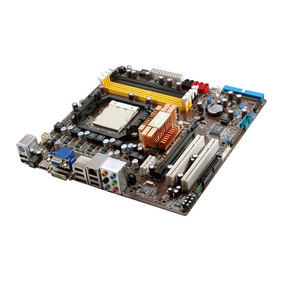
Page 20: Motherboard Overview
Motherboard overview 1.5.1 Motherboard layout 24.4cm (9.6in) KB_USB56 CPU_FAN ATX12V SPDIF_O2 USB34_ESATA LAN1_USB12 SATA5 SATA4 SATA3 AUDIO Nvidia SATA2 MCP78S SATA1 PCIEX1_1 SB_PWR CLRTC Realtek 8211CL-GR PCIEX16 CR2032 3V Lithium Cell M3N78-VM CMOS Power PCI1 Super I/O BIOS PCI2 USB78 USB1112 VT1708B CHASSIS... -
Page 21: Placement Direction
Place eight (8) screws into the holes indicated by circles to secure the motherboard to the chassis. Do not overtighten the screws! Doing so can damage the motherboard. Place this side towards the rear of the chassis M3N78-VM ASUS M3N78-VM... -
Page 22: Central Processing Unit (Cpu)
Central Processing Unit (CPU) The motherboard comes with a 940-pin AM2+ / AM2 socket designed for the AMD Athlon™ 64 / Sempron™ / Athlon™ FX / Athlon™ 64 X2 / AM2+ / Phenom™ FX / Phenom™ processor. The AM2+ / AM2 socket has a different pinout from the 940-pin socket designed for the AMD Opteron™... - Page 23 Connect the CPU fan cable to the CPU_FAN connector on the motherboard. CPU_FAN M3N78-VM M3N78-VM CPU Fan Connector Do not forget to connect the CPU fan connector! Hardware monitoring errors can occur if you fail to plug this connector. ASUS M3N78-VM 1-11...
-
Page 24: Installing The Heatsink And Fan
1.6.2 Installing the heatsink and fan The AMD Athlon™ 64 / Sempron™ / Athlon™ FX / Athlon™ 64 X2 / AM2+ / Phenom™ FX / Phenom™ processor requires a specially designed heatsink and fan assembly to ensure optimum thermal condition and performance. Ensure that you use only qualified heatsink and fan assembly. - Page 25 Otherwise, you cannot snap the retention bracket in place. Push down the retention bracket lock on the retention mechanism to secure the heatsink and fan to the module base. ASUS M3N78-VM 1-13...
-
Page 26: System Memory
System memory 1.7.1 Overview The motherboard comes with four Double Data Rate 2 (DDR2) Dual Inline Memory Modules (DIMM) sockets. A DDR2 module has the same physical dimensions as a DDR DIMM but has a 240-pin footprint compared to the 184-pin DDR DIMM. DDR2 DIMMs are notched differently to prevent installation on a DDR DIMM socket. - Page 27 The motherboard can support 8 GB physical memory on the operating system listed below. You may install a maximum of 2 GB DIMMs on each slot. 64-bit Windows XP Professional x64 Edition ® Windows Vista x64 Edition ® ASUS M3N78-VM 1-15...
-
Page 28: Qualified Vendors Lists
Qualified Vendors Lists (QVL) DDR2-533 MHz capability Size Vendor Model Brand Component DIMM support 512MB Kingston KVR533D2N4/512 Infineon HYB18T512800AF3733336550 · · 512MB Samsung M378T6553BG0-CD5 Samsung K4T51083QB-GCD5 · · HYMP512U64CP8-C4 AB Hynix HY5PS12821CFP-C4 · · 512MB Micron MT 16HTF6464AG-53EB2 Micron D9BOM ·... - Page 29 Dual-channel memory configuration. • C*: Supports four modules inserted into both the yellow slots and the black slots as two pairs of Dual-channel memory configuration. Visit the ASUS website for the latest DDR2-667/800/1066MHz QVL. ASUS M3N78-VM 1-17...
-
Page 30: Installing A Dimm
1.7.3 Installing a DIMM Ensure to unplug the power supply before adding or removing DIMMs or other system components. Failure to do so may cause severe damage to both the motherboard and the components. Unlock a DIMM socket by pressing DDR2 DIMM notch the retaining clips outward. -
Page 31: Expansion Slots
Turn on the system and change the necessary BIOS settings, if any. See Chapter 2 for information on BIOS setup. Assign an IRQ to the card. Refer to the tables on the next page. Install the software drivers for the expansion card. ASUS M3N78-VM 1-19... -
Page 32: Interrupt Assignments
Interrupt assignments Standard function Standard timer Keyboard High precision event timer IRQ holder for PCI steering COM1 IRQ holder for PCI steering Floppy controller Printer port High precision event timer AMD ACPI-Compliant system IRQ holder for PCI steering IRQ holder for PCI steering Microsoft PS/2 mouse Numeric data processor Primary IDE... -
Page 33: Irq Assignments For This Motherboard
When using PCI cards on shared slots, ensure that the drivers support “Share IRQ” or that the cards do not need IRQ assignments. Otherwise, conflicts will arise between the two PCI groups, making the system unstable and the card inoperable. ASUS M3N78-VM 1-21... -
Page 34: Pci Slots
1.8.3 PCI slots The PCI slots support cards such as a LAN card, SCSI card, USB card, and other cards that comply with PCI specifications. The figure shows a LAN card installed on a PCI slot. 1.8.4 PCI Express x1 slot This motherboard supports PCI Express x1 network cards, SCSI cards and other cards that comply with the PCI Express... -
Page 35: Jumper
You do not need to clear the RTC when the system hangs due to overclocking. For system failure due to overclocking, use the C.P.R. (CPU Parameter Recall) feature. Shut down and reboot the system so the BIOS can automatically reset parameter settings to default values. ASUS M3N78-VM 1-23... -
Page 36: 1.10 Connectors
1.10 Connectors 1.10.1 Rear panel connectors PS/2 keyboard/mouse combo port (purple). This port is for a PS/2 keyboard or mouse. Video Graphics Adapter (VGA) port. This 15-pin port is for a VGA monitor or other VGA-compatible devices. USB 2.0 ports 3 and 4. These two 4-pin Universal Serial Bus (USB) ports are available for connecting USB 2.0 devices. - Page 37 • Due to the chipset limitation, simultaneous output for DVI and HDMI is not supported. • To play HD DVD or BLU-Ray Disc, ensure to use an HDCP compliant monitor. ASUS M3N78-VM 1-25...
- Page 38 Playback of HD DVD and Blu-Ray Discs The speed and bandwidth of the CPU/Memory, DVD player, and drivers will affect the playback quality. Using the CPU/Memory of higher speed and bandwidth with the higher-version DVD player and drivers will upgrade the playback quality.
-
Page 39: Internal Connectors
This connector supports a Trusted Platform Module (TPM) system, which can securely store keys, digital certificates, passwords, and data. A TPM system also helps enhance network security, protects digital identities, and ensures platform integrity. M3N78-VM M3N78-VM TPM Connector The TPM model is purchased separately! ASUS M3N78-VM 1-27... - Page 40 IDE connectors (40-1 pin PRI_IDE) The onboard IDE connector is for an Ultra DMA 133/100/66 signal cable. There are three connectors on each Ultra DMA 133/100/66 signal cable: blue, black, and gray. Connect the blue connector to the motherboard’s IDE connector, then select one of the following modes to configure your device(s).
- Page 41 SATA Mode select item in the BIOS to [RAID Mode]. See the page 2-18 for details. • Due to the chipset’s limitation, SATA 4 and SATA 5 do not support IDE mode, only support AHCI+RAID mode. ASUS M3N78-VM 1-29...
- Page 42 CPU, Chassis and Power Fan connectors (4-pin CPU_FAN, 3-pin CHA_FAN, 3-pin PWR_FAN) The fan connectors support cooling fans of 350mA~740mA (8.88W max.) or a total of 1A~2.22A (26.64W max.) at +12V. Connect the fan cables to the fan connectors on the motherboard, ensuring that the black wire of each cable matches the ground pin of the connector.
- Page 43 Optical drive audio in connector (4-pin CD) These connectors allow you to receive stereo audio input from sound sources such as a CD-ROM, TV tuner, or MPEG card. (black) Right Audio Channel Ground Ground Left Audio Channel M3N78-VM M3N78-VM Internal Audio Connector ASUS M3N78-VM 1-31...
-
Page 44: Front Panel Audio Connector
Serial port connectors (10-1 pin COM1) The connector is for a serial (COM) port. Connect the serial port module cable to the connector, then install the module to a slot opening at the back of the system chassis. The serial port bracket (COM1) is purchased separately. COM1 M3N78-VM M3N78-VM COM Port Connector... -
Page 45: Lpt Connector
M3N78-VM Intrusion Connector 12. LPT connector The LPT (Line Printing Terminal) connector supports devices such as a printer. LPT standardizes as IEEE 1284, which is the parallel port interface on IBM PC-compatible computers. M3N78-VM M3N78-VM Parallel Port Connector ASUS M3N78-VM 1-33... -
Page 46: Atx Power Connectors
• If you are uncertain about the minimum power supply requirement for your system, refer to the Recommended Power Supply Wattage Calculator at http://support.asus.com/PowerSupplyCalculator/PSCalculator. aspx?SLanguage=en-us for details. • You must install a PSU with a higher power rating if you intend to install additional devices. -
Page 47: System Panel Connector
BIOS settings. Pressing the power switch for more than four seconds while the system is ON turns the system OFF. Reset button (2-pin Reset) • This 2-pin connector is for the chassis-mounted reset button for system reboot without turning off the system power. ASUS M3N78-VM 1-35... - Page 48 1-36 Chapter 1: Product introduction...
-
Page 49: Chapter 2: Bios Setup
This chapter tells how to change the system settings through the BIOS Setup menus. Detailed descriptions of the BIOS parameters are also provided. BIOS setup... -
Page 50: Managing And Updating Your Bios
The following utilities allow you to manage and update the motherboard Basic Input/Output System (BIOS) setup. ASUS EZ Flash 2: Updates the BIOS using a floppy disk, USB Flash, or the motherboard support DVD during POST. ASUS AFUDOS: Updates the BIOS in DOS mode using a bootable floppy disk. - Page 51 Right-click Floppy Disk Drive then click Format to display the Format 3 1/2 Floppy dialog box . d. Select the Create an MS-DOS startup disk check box. e. Click Start. Copy the original or the latest motherboard BIOS file to the bootable floppy disk. ASUS M3N78-VM...
-
Page 52: Asus Ez Flash 2 Utility
2.1.2 ASUS EZ Flash 2 utility The ASUS EZ Flash 2 feature allows you to update the BIOS without having to go through the long process of booting from a floppy disk and using a DOS-based utility. The EZ Flash 2 utility is built-in the BIOS chip so it is accessible by pressing <Alt>... -
Page 53: Afudos Utility
Extension name Press <Enter>. The utility copies the current BIOS file to the floppy disk. A:\>afudos /oOLDBIOS1.rom AMI Firmware Update Utility - Version 1.19(ASUS V2.29(03.11.24BB)) Copyright (C) 2002 American Megatrends, Inc. All rights reserved. Reading flash ..done Write to file..ok A:\>... -
Page 54: Updating The Bios File
Updating the BIOS file To update the BIOS file using the AFUDOS utility: Visit the ASUS website (www.asus.com) and download the latest BIOS file for the motherboard. Save the BIOS file to a bootable floppy disk. Write the BIOS filename on a piece of paper. You need to type the exact BIOS filename at the DOS prompt. -
Page 55: Asus Crashfree Bios 3 Utility
2.1.4 ASUS CrashFree BIOS 3 utility The ASUS CrashFree BIOS 3 is an auto recovery tool that allows you to restore the BIOS file when it fails or gets corrupted during the updating process. You can update a corrupted BIOS file using the motherboard support DVD , the floppy disk or the USB flash disk that contains the updated BIOS file. -
Page 56: Recovering The Bios From The Support Dvd
Restart the system after the utility completes the updating process. • Only the USB flash disk with FAT 32/16 format and single partition can support ASUS CrashFree BIOS 3. The device size should be smaller than 8GB. • DO NOT shut down or reset the system while updating the BIOS! Doing so... -
Page 57: Asus Update Utility
2.1.5 ASUS Update utility The ASUS Update is a utility that allows you to manage, save, and update the motherboard BIOS in Windows environment. The ASUS Update utility allows you ® • Save the current BIOS file • Download the latest BIOS file from the Internet •... - Page 58 To update the BIOS through the Internet: desktop by clicking Start Launch the ASUS Update utility from the Windows ® > Programs > ASUS > ASUSUpdate > ASUSUpdate. The ASUS Update main window appears. Select Update BIOS from Select the ASUS FTP site nearest...
- Page 59 To update the BIOS through a BIOS file: Launch the ASUS Update utility from the Windows desktop by clicking Start ® > Programs > ASUS > ASUSUpdate > ASUSUpdate. The ASUS Update main window appears. Select Update BIOS from a file option from the drop-down menu, then click Next.
-
Page 60: Bios Setup Program
The BIOS setup screens shown in this section are for reference purposes only, and may not exactly match what you see on your screen. • Visit the ASUS website (www.asus.com) to download the latest BIOS file for this motherboard. 2-12... -
Page 61: Bios Menu Screen
• The BIOS setup screens shown in this chapter are for reference purposes only, and may not exactly match what you see on your screen. • Visit the ASUS website (www.asus.com) to download the latest BIOS information. ASUS M3N78-VM 2-13... -
Page 62: Navigation Keys
2.2.3 Navigation keys At the bottom right corner of a menu screen are the navigation keys for that particular menu. Use the navigation keys to select items in the menu and change the settings. Some of the navigation keys differ from one screen to another. 2.2.4 Menu items The highlighted item on the menu bar displays the specific items for that menu. -
Page 63: Main Menu
Allows you to set the system date. 2.3.3 Legacy Diskette A [1.44M, 3.5 in.] Sets the type of floppy drive installed. Configuration options: [Disabled] [360K , 5.25 in.] [1.2M, 5.25 in.] [720K, 3.5 in] [1.44M 3.5 in] [2.88M, 3.5 in] ASUS M3N78-VM 2-15... -
Page 64: Primary Ide Master/Slave, Sata1~3, Esata
2.3.4 Primary IDE Master/Slave, SATA1~3, ESATA While entering Setup, the BIOS automatically detects the presence of IDE devices. There is a separate sub-menu for each IDE device. Select a device item then press <Enter> to display the IDE device information. Select the type Primary IDE Master of device connected... - Page 65 Configuration options: [Auto] [Disabled] [Enabled] 32Bit Data Transfer [Enabled] Enables or disables 32-bit data transfer. Configuration options: [Disabled] [Enabled] ASUS M3N78-VM 2-17...
-
Page 66: Storage Configuration
2.3.5 Storage Configuration The items in this menu allow you to set or change the configurations for the IDE devices installed in the system. Select an item then press <Enter> if you wish to configure the item. DISABLED: disables IDE Configuration the integrated IDE Controller. -
Page 67: System Information
: AMD Sempron(tm) Processor 3200+ Speed : 1800MHz Count System Memory Installed Size : 512MB Usable Size : 384MB AMI BIOS Displays the auto-detected BIOS information Processor Displays the auto-detected CPU specification System Memory Displays the auto-detected system memory ASUS M3N78-VM 2-19... -
Page 68: Advanced Menu
Advanced menu The Advanced menu items allow you to change the settings for the CPU and other system devices. Take caution when changing the settings of the Advanced menu items. Incorrect field values can cause the system to malfunction. Adjust System JumperFree Configuration Frequency/Voltage etc. - Page 69 Allows you to select the overclock options. Configuration options: [Auto] [Overclock 3%] [Overclock 5%] [Overclock 7%] [Test Mode] Memory Over Voltage [Auto] Allows you to adjust the Memory Over Voltage. Configuration options: [Auto] [20mV] [40mV] [60mV] [80mV] ~ [1280mV] ASUS M3N78-VM 2-21...
-
Page 70: Cpu Configuration
2.4.2 CPU Configuration CPU Configuration This option should Module Version: 13.20 remain disabled for AGESA Version: 3.1.6.0 the normal operation. Physical Count: 1 The driver developer Logical Count: 1 may enable it for AMD Athlon(tm) Processor 3200+ testing purpose. Revision: F2 Cache L1: 128KB Cache L2: 128KB Cache L3: N/A... -
Page 71: Chipset
Enable Clock to All DIMMs [Disabled] MemClk Tristate C3/ATLVID [Disabled] Memory Hole Remapping [Enabled] DCT Unganged Mode [Always] Power Down Enable [Enabled] Bank Interleaving [Auto] Allows you to enable the bank memory interleaving. Configuration options: [Disabled] [Auto] ASUS M3N78-VM 2-23... -
Page 72: Dram Timing Configuration
Channel Interleaving [Disabled] Allows you to enable the channel memory interleaving. Configuration options: [Disabled] [Address bits 6] [Address bits 12] [XOR of Address bits [20:16,6] ] [XOR of Address bits [20:16,9] ] Enable Clock to All DIMMs [Disabled] Enables or disables clock to all DIMMs. Configuration options: [Disabled] [Enabled] MemClk Tristate C3/ALTVID [Disabled] Enables or disables the MemClk Tristate C3/ALTVID. -
Page 73: Ecc Configuration
Disables or sets the Data/L2/L3 Cache BG Scrub. This item allows the cache RAM to be corrected when idle. Configuration options: [Disabled] [40ns] [80ns] [160na] [320ns] [640ns] [1.28us] [2.56us] [5.12us] [10.2us] [20.5us] [41.0us] [81.9us] [163.8us] [327.7us] [655.4us] [1.31ms] [2.62ms] [5.24ms] [10.49ms] [20.97ms] [42.00ms] [84.00ms] ASUS M3N78-VM 2-25... -
Page 74: Southbridge Configuration
SouthBridge Configuration SouthBridge chipset Configuration Options PCI VGA Card First Primary Graphics Adapter [PCIE VGA Card Firs] Internal VGA First Hybrid SLI Mode [mGPU Auto] PCIE VGA Card First Hybrid SLI Frame buffer Size [128MB] AZALIA Audio [Internal codec+E} Front Panel Select [HD Audio] SPDIF Mode Setting [SPDIF Output]... -
Page 75: Onboard Devices Configuration
Parallel Port Address [378] Allows you to select the Parallel Port base addresses. Configuration options: [Disabled] [378] [278] [3BC] Parallel Port Mode [Normal] Allows you to select the Parallel Port mode. Configuration options: [Normal] [EPP] [ECP] [EPP+ECP] ASUS M3N78-VM 2-27... -
Page 76: Pci Pnp
2.4.5 PCI PnP The PCI PnP menu items allow you to change the advanced settings for PCI/PnP devices. The menu includes setting IRQ and DMA channel resources for either PCI/PnP or legacy ISA devices, and setting the memory size block for legacy ISA devices. -
Page 77: Usb Configuration
If no USB device is detected, the legacy USB support is disabled. Configuration options: [Disabled] [Enabled] [Auto] USB 2.0 Controller Mode [HiSpeed] Allows you to configure the USB 2.0 controller in HiSpeed (480 Mbps) or Full Speed (12 Mbps). Configuration options: [Full Speed] [HiSpeed] ASUS M3N78-VM 2-29... -
Page 78: Trusted Computing
2.4.7 Trusted Computing The items in this menu allows you to configure Trusted Computing related settings. Select an item then press <Enter> to display the configuration options. Enable/Disable TPM Trusted Computing TCG (TPM 1.1/1.2) supp TCG/TPM SUPPORT [No] in BIOS TCG/TPM SUPPORT [No] Allows you to enable or disable the TPM/TCG (TPM 1.1/1.2) support in BIOS. -
Page 79: Power Menu
Allows you to enable or disable the Advanced Configuration and Power Interface (ACPI) support in the Application-Specific Integrated Circuit (ASIC). When set to Enabled, the ACPI APIC table pointer is included in the RSDT pointer list. Configuration options: [Disabled] [Enabled] ASUS M3N78-VM 2-31... -
Page 80: Apm Configuration
2.5.4 APM Configuration APM Configuration Options Restore on AC Power Loss [Power Off] Power On Power Off Power On By PCI Device [Disabled] Last State Power On By Ring [Disabled] Power On By PS/2 KB/MS [Disabled] Power On By RTC Alarm [Disabled] Restore on AC Power Loss [Power Off] When set to Power Off, the system goes into off state after an AC power loss. -
Page 81: Hardware Monitor
The onboard hardware monitor automatically detects the voltage output through the onboard voltage regulators. Smart Q-Fan Function [Disabled] Allows you to enable or disable the ASUS Q-Fan feature that smartly adjusts the fan speeds for more efficient system operation. Configuration options: [Disabled] [Enabled]... -
Page 82: Boot Menu
Boot menu The Boot menu items allow you to change the system boot options. Select an item then press <Enter> to display the sub-menu. Specifies the Boot Boot settings Device Priority sequence. Boot Device Priority A virtual floopy disk drive (Floppy Drive Boot Settings Configuration B:) may appear when Security... -
Page 83: Boot Settings Configuration
This allows you to enable or disable the full screen logo display feature. Configuration options: [Disabled] [Enabled] Set this item to [Enabled] to use the ASUS MyLogo 2™ feature. Add On ROM Display Mode [Force BIOS] Sets the display mode for option ROM. Configuration options: [Force BIOS] [Keep... -
Page 84: Security
Interrupt 19 Capture [Disabled] When set to [Enabled], this function allows the option ROMs to trap Interrupt 19. Configuration options: [Disabled] [Enabled] 2.6.3 Security The Security menu items allow you to change the system security settings. Select an item then press <Enter> to display the configuration options. Security Settings <Enter>... -
Page 85: Change User Password
Password Check [Setup] When set to [Setup], BIOS checks for user password when accessing the Setup utility. When set to [Always], BIOS checks for user password both when accessing Setup and booting the system. Configuration options: [Setup] [Always] ASUS M3N78-VM 2-37... -
Page 86: Tools Menu
AI NET 2 2.7.1 ASUS EZ Flash 2 Allows you to run ASUS EZ Flash 2. When you press <Ok>, a confirmation message appears. Use the left/right arrow key to select between [Yes] or [No], then press <Ok> to confirm your choice. -
Page 87: Express Gate
Check Realtek Phy Pair Status Length LAN cable during POST. Check Realtek Phy LAN cable [Disabled] Check Realtek Phy LAN cable [Disabled] Allows you enable or disable checking Realtek Phy LAN cable during POST. Configuration options: [Disabled] [Enabled] ASUS M3N78-VM 2-39... -
Page 88: Exit Menu
Exit menu The Exit menu items allow you to load the optimal or failsafe default values for the BIOS items, and save or discard your changes to the BIOS items. Exit system setup Exit Options after saving the Exit & Save Changes changes. -
Page 89: Chapter 3: Software Support
This chapter describes the contents of the support DVD that comes with the motherboard package. Software support... -
Page 90: Installing An Operating System
The contents of the support DVD are subject to change at any time without notice. Visit the ASUS website (http://www.asus.com) for updates. 3.2.1 Running the support DVD Place the support DVD in the optical drive. -
Page 91: Drivers Menu
The drivers menu shows the available device drivers if the system detects installed devices. Install the necessary drivers to activate the devices. ASUS InstAll - Installation Wizard for Drivers Launches the ASUS InstallAll installation wizard for drivers. AMD Cool ‘n’ Quiet Driver Installs the AMD Cool ‘n’ Quiet driver. -
Page 92: Utilities Menu
ASUS InstAll - Installation Wizard for Utilities Launches the ASUS InstallAll installation wizard for utilities. ASUS Update The ASUS Update utility allows you to update the motherboard BIOS in a Windows environment. This utility requires an Internet connection either through a ®... - Page 93 Corel MediaOne Starter Installs the Corel MediaOne Starter. CyberLink PowerBackup Installs the CyberLink PowerBackup. ASUS Express Gate Installer Installs the ASUS Express Gate. WinZip 11 Installs the WinZip 11. Ulead Burn. Now Installs the Ulead Burn.Now. Click to show the succeeding Utilities menu below.
-
Page 94: Make Disk Menu
3.2.4 Make Disk menu The Make Disk menu allows you to make a RAID driver disk. NVIDIA 32/64bit XP SATA RAID Driver (Disk1/2) Allows you to create the NVIDIA 32/64-bit XP SATA RAID Driver disks for Windows XP Operating System (OS). ®... - Page 95 Vista, install the AHCI / RAID driver through the motherboard support ® DVD or a USB device. Find RAID driver in the support DVD through the path below: Drivers\Chipset\Disk\RAID Find AHCI driver in the support DVD through the path below: Drivers\Chipset\Disk\AHCI ASUS M3N78-VM...
-
Page 96: Manual Menu
Reader from the Utilities menu before opening a user manual ® ® file. 3.2.6 ASUS Contact information Click the Contact tab to display the ASUS contact information. You can also find this information on the inside front cover of this user guide. Chapter 3: Software support... -
Page 97: Other Information
The icons on the top right corner of the screen give additional information on the motherboard and the contents of the support DVD. Click an icon to display the specified information. Motherboard Info Displays the general specifications of the motherboard. Browse this DVD Displays the support DVD contents in graphical format. ASUS M3N78-VM... -
Page 98: Technical Support Form
Technical support Form Displays the ASUS Technical Support Request Form that you have to fill out when requesting technical support. Filelist Displays the contents of the support DVD and a brief description of each in text format. 3-10 Chapter 3: Software support... -
Page 99: Creating A Raid Driver Disk
During the OS installation, the system prompts you to press the F6 key to install third-party SCSI or RAID driver. Press <F6> then insert the floppy disk with RAID driver into the floppy disk drive. Follow the succeeding screen instructions to complete the installation. ASUS M3N78-VM 3-11... - Page 100 Using the driver disks you created: • Insert Disk1 when you see the following instruction in Windows Setup. DO NOT remove Disk1 until you are asked to insert Disk2. Windows Setup Please insert the disk labeled Manufacturer-supplied hardware support disk into Drive A: Press ENTER when ready.
- Page 101 Find AHCI driver in the support DVD through the path below: Drivers\Chipset\Disk\AHCI Follow the succeeding screen instructions to complete the installation. Due to chipset limitation, the Serial ATA ports supported by the NVIDIA chipset does not support Serial Optical Disk Drives (Serial ODD) under DOS. ASUS M3N78-VM 3-13...
- Page 102 3-14 Chapter 3: Software support...
-
Page 103: Chapter 4: Nvidia ® Technology Support
This chapter tells how to use the Hybrid feature. ® ® NVIDIA technology support... -
Page 104: Nvidia Hybrid Sli Technology
® ® NVIDIA Hybrid SLI Technology The motherboard supports the NVIDIA Hybrid SLI technology that includes two ® ® primary features: GeForce ® Boost and HybridPower™. GeForce ® Boost enhances the performance of NVIDIA discrete Graphics Process Units (dGPU) when they work with the onboard motherboard GPU (mGPU). -
Page 105: Enabling Hybrid Sli
[mGPU always enable] PCIE VGA Card First Hybrid SLI Frame buffer Size [256MB] AZALIA Audio [Internal codec+E} Front Panel Select [HD Audio] SPDIF Mode Setting [SPDIF Output] Onboard LAN [Auto] OnBoard LAN Boot ROM [Disabled] SouthBridge ACPI HPET TABLE [Enabled] ASUS M3N78-VM... - Page 106 Save your changes and Exit Setup. desktop, go to Start > Control Panel > User Accounts From the Windows ® and Family Safety to turn off User Account Control. Place the support DVD into the optical drive, and go to the Drivers menu to install the NVIDIA Chipset Driver Program.
Need help?
Do you have a question about the M3N78 PRO GREEN and is the answer not in the manual?
Questions and answers