Table of Contents
Advertisement
Quick Links
Advertisement
Table of Contents

Related Manuals for Asus M3N78-AM


Summary of Contents for Asus M3N78-AM
- Page 1 M3N78-AM...
- Page 2 Product warranty or service will not be extended if: (1) the product is repaired, modified or altered, unless such repair, modification of alteration is authorized in writing by ASUS; or (2) the serial number of the product is defaced or missing.
-
Page 3: Table Of Contents
Contents Notices ......................vi Safety information ..................vii About this guide ..................vii M3N78-AM specifications summary ............ix Chapter 1: Product introduction Welcome! ..................1-1 Package contents ................. 1-1 Special features ................1-1 1.3.1 Product highlights ............1-1 1.3.2 Innovative ASUS features ..........1-3 Before you proceed .............. - Page 4 2.1.1 Creating a bootable floppy disk ........2-1 2.1.2 ASUS Update utility ............2-2 2.1.3 ASUS EZ Flash 2 utility ........... 2-3 2.1.4 AFUDOS utility ..............2-4 2.1.5 ASUS CrashFree BIOS 3 utility ........2-5 BIOS setup program ..............2-6 2.2.1...
- Page 5 2.5.5 Hardware Monitor ............2-20 Boot menu .................. 2-21 2.6.1 Boot Device Priority ............2-21 2.6.2 Boot Settings Configuration .......... 2-21 2.6.3 Security ................. 2-22 Tools menu ................. 2-24 2.7.1 ASUS EZ Flash 2 ............2-24 Exit menu ..................2-25...
-
Page 6: Notices
Notices Federal Communications Commission Statement This device complies with Part 15 of the FCC Rules. Operation is subject to the following two conditions: • This device may not cause harmful interference, and • This device must accept any interference received including interference that may cause undesired operation. -
Page 7: Safety Information
Safety information Electrical safety • To prevent electrical shock hazard, disconnect the power cable from the electrical outlet before relocating the system. • When adding or removing devices to or from the system, ensure that the power cables for the devices are unplugged before the signal cables are connected. If possible, disconnect all power cables from the existing system before you add a device. - Page 8 Refer to the following sources for additional information and for product and software updates. ASUS websites The ASUS website provides updated information on ASUS hardware and software products. Refer to the ASUS contact information. Optional documentation Your product package may include optional documentation, such as warranty flyers, that may have been added by your dealer.
-
Page 9: M3N78-Am Specifications Summary
3GB or less. For effective use of memory, we recommend that you install a 64-bit Windows OS when have 4GB or more memory installed on the motherboard. *** Refer to www.asus.com or this user manual for the Memory QVL (Qualified Vendors List) Expansion slots 1 x PCI Express™... - Page 10 ASUS unique features ASUS Quiet Thermal Solution: - ASUS Q-Fan ASUS EZ DIY: - ASUS CrashFree BIOS 3 - ASUS EZ Flash 2 Audio ALC662 High Definition Audio 6-channel CODEC - Supports S/PDIF out interface, Jack-detect, Multi-streaming, and Anti Pop Function Other features ASUS MyLogo2™...
-
Page 11: Chapter 1: Product Introduction
® The motherboard delivers a host of new features and latest technologies, making it another standout in the long line of ASUS quality motherboards! Before you start installing the motherboard, and hardware devices on it, check the items in your package with the list below. - Page 12 This enhances system performance in 3D graphics and other memory demanding applications. • DDR2 1066 is supported by AM2+ CPU only. Refer to the ASUS website at www.asus.com for the supported CPU models. • Due to AM2+ CPU limitation, only one DDR2 1066 DIMM is supported per channel.
-
Page 13: Innovative Asus Features
BIOS file using the bundled support DVD, floppy disk, or USB disk that contains the BIOS file. ASUS EZ Flash 2 ASUS EZ Flash 2 is a utility that allows you to update the BIOS without using a bootable floppy disk or a DOS-based utility. ASUS Q-Fan... - Page 14 This motherboard and its packaging comply with the European Union’s Restriction on the use of Hazardous Substances (RoHS). This is in line with the ASUS vision of creating environment-friendly and recyclable products/packaging to safeguard consumers’ health while minimizing the impact on the environment.
-
Page 15: Before You Proceed
ON, in sleep mode, or in soft-off mode. This is a reminder that you should shut down the system and unplug the power cable before removing or plugging in any motherboard component. The illustration below shows the location of the onboard LED. SB_PWR M3N78-AM Standy Power Powered Off M3N78-AM Onboard LED Chapter 1: Product introduction... -
Page 16: Motherboard Overview
Screw holes Place eight screws into the holes indicated by circles to secure the motherboard to the chassis. Do not overtighten the screws! Doing so can damage the motherboard. Place this side towards the rear of the chassis. M3N78-AM ASUS M3N78-AM... -
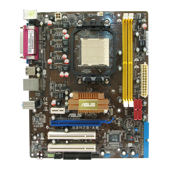
Page 17: Motherboard Layout
21.8cm(8.6in) CPU_FAN KB_USB56 ATX12V USB34 LAN1_USB12 NVIDIA ® AUDIO GeForce 8200 PCIEX1_1 Realtek 8211CL SB_PWR PCIEX16 Lithium Cell CMOS Power M3N78-AM CLRTC SPEAKER PCI1 Super BIOS PCI2 SPDIF_OUT USB910 USB78 USB1112 FLOPPY F_PANEL AAFP 1.5.4 Layout contents Connectors/Jumpers/Slots Page Connectors/Jumpers/Slots... -
Page 18: Central Processing Unit (Cpu)
1.6.1 Installing the CPU To install a CPU: Locate the CPU socket on the motherboard. M3N78-AM M3N78-AM CPU Socket AM2+ Press the lever sideways to unlock the socket, then lift it up to a 90°- Socket lever 100° angle. Ensure that the socket lever is lifted up to 90°-100° angle, otherwise the CPU will not fit in completely. - Page 19 Connect the CPU fan cable to the CPU_FAN connector on the motherboard. CPU_FAN M3N78-AM M3N78-AM CPU fan connector Do not forget to connect the CPU fan connector! Hardware monitoring errors can occur if you fail to plug this connector. Chapter 1: Product introduction...
-
Page 20: Installing The Heatsink And Fan
Your boxed CPU heatsink and fan assembly should come with installation instructions for the CPU, heatsink, and the retention mechanism. If the instructions in this section do not match the CPU documentation, follow the latter. Attach one end of the retention bracket to the retention module base. 1-10 ASUS M3N78-AM... -
Page 21: System Memory
240-pin footprint compared to the 184-pin DDR DIMM. DDR2 DIMMs are notched differently to prevent installation on a DDR DIMM socket. The figure illustrates the location of the DDR2 DIMM sockets: Channel Sockets Channel A DIMM_A1 Channel B DIMM_B1 M3N78-AM M3N78-AM 240-pin DDR2 DIMM sockets Chapter 1: Product introduction 1-11... -
Page 22: Memory Configurations
The motherboard supports up to 8GB memory modules on Windows XP Professional x64 ® and Vista x64 editions. You may install a maximum of 2 GB DIMMs on each slot. M3N78-AM Motherboard Qualified Vendors Lists (QVL) DDR2-1066MHz capability DIMM Chip... - Page 23 DDR2-800MHz capability DIMM Chip support Vendor Part No. Size Chip No. Brand Kingston KHX6400D2LLK2/1GN 512MB Heat-Sink Package Kingston • • Kingston KVR800D2N5/1G E5108AJBG-8E-E Elpida • • Samsung M378T2863QZS-CF7 K4T1G084QQ-HCF7 Samsung • • Samsung M391T2863QZ3-CF7 K4T1G084QQ-HCF7(ECC) Samsung • • Samsung M378T5263AZ3-CF7 K4T2G084QA-HCF7 Samsung •...
- Page 24 Supports one module inserted into any slot as Single-channel memory configuration. • B*: Supports one pair of modules inserted into both the yellow slots as one pair of Dual-channel memory configuration. Visit the ASUS website at www.asus.com for the latest DDR2-533/667/800/1066MHz QVL. 1-14 ASUS M3N78-AM...
-
Page 25: Installing A Dimm
1.7.3 Installing a DIMM Unplug the power supply before adding or removing DIMMs or other system components. Failure to do so can cause severe damage to both the motherboard and the components. Press the retaining clips outward to DDR2 DIMM notch unlock a DDR2 DIMM socket. -
Page 26: Expansion Slots
This motherboard supports PCI Express x1 network cards, SCSI cards, and other cards that comply with the PCI Express specifications. 1.8.6 PCI Express x16 slot This motherboard supports a PCI Express x16 graphics card that complies with the PCI Express specifications. 1-16 ASUS M3N78-AM... -
Page 27: Jumpers
Normal Clear RTC (Default) M3N78-AM Clear RTC RAM To erase the RTC RAM: 1. Turn OFF the computer and unplug the power cord. 2. Move the jumper cap from pins 1-2 (default) to pins 2-3. Keep the cap on pins 2-3 for about 5~10 seconds, then move the cap back to pins 1-2. -
Page 28: Connectors
4, or 6-channel configuration. Audio 2, 4, 6-channel configuration Port Headset 2-channel 4-channel 6-channel Light Blue Line In Rear Speaker Out Rear Speaker Out Lime Line Out Front Speaker Out Front Speaker Out Pink Mic In Mic In Bass/Center 1-18 ASUS M3N78-AM... -
Page 29: Internal Connectors
If any device jumper is set as “Cable-Select,” make sure all other device jumpers have the same setting. PRI_IDE M3N78-AM NOTE:Orient the red markings on the IDE ribbon cable to PIN 1. M3N78-AM IDE connector Chapter 1: Product introduction 1-19... - Page 30 NOTE:Orient the red markings on the floppy ribbon cable to PIN 1. M3N78-AM Floppy disk drive connector Serial ATA connectors (7-pin SATA1, SATA2, SATA3, SATA4) These connectors are for the Serial ATA signal cables for Serial ATA 3Gb/s hard disk and optical disk drives.
- Page 31 The system may become unstable or may not boot up if the power is inadequate. • If you are uncertain about the minimum power supply requirement for your system, refer to the Recommended Power Supply Wattage Calculator at http://support.asus. com/PowerSupplyCalculator/PSCalculator.aspx?SLanguage=en-us for details. Optical drive audio in connector (4-pin CD) This connector allows you to receive stereo audio input from sound sources such as a CD-ROM, TV tuner, or MPEG card.
- Page 32 PIN 1 M3N78-AM HD_LED RESET M3N78-AM System panel connector System power LED (2-pin PLED) • This 2-pin connector is for the system power LED. Connect the chassis power LED cable to this connector. The system power LED lights up when you turn on the system power, and blinks when the system is in sleep mode.
- Page 33 Legacy AC’97 pin definition compliant definition M3N78-AM Analog front panel connector • We recommend that you connect a high-definition front panel audio module to this connector to avail of the motherboard high-definition audio capability. • By default, this connector is set to [HD Audio]. If you want to connect a High Definition front panel audio module to this connector, set the Front Panel Select item in the BIOS to [HD Audio].
- Page 34 DO NOT forget to connect the fan cables to the fan connectors. Insufficient air flow inside the system may damage the motherboard components. These are not jumpers! DO NOT place jumper caps on the fan connectors. Only the CPU FAN supports ASUS Q-Fan. CPU_FAN M3N78-AM...
-
Page 35: Software Support
The contents of the Support DVD are subject to change at any time without notice. Visit the ASUS website at www.asus.com for updates. To run the Support DVD Place the Support DVD to the optical drive. - Page 36 1-26 ASUS M3N78-AM...
-
Page 37: Chapter 2: Bios Information
Save a copy of the original motherboard BIOS file to a floppy disk or a USB flash disk in case you need to restore the BIOS in the future. Copy the original motherboard BIOS using the ASUS Update or AFUDOS utilities. 2.1.1 Creating a bootable floppy disk Create a bootable floppy disk using a different computer. -
Page 38: Asus Update Utility
2.1.2 ASUS Update utility The ASUS Update is a utility that allows you to manage, save, and update the motherboard BIOS in Windows environment. ® • ASUS Update requires an Internet connection either through a network or an Internet Service Provider (ISP). -
Page 39: Asus Ez Flash 2 Utility
2.1.3 ASUS EZ Flash 2 utility The ASUS EZ Flash 2 feature allows you to update the BIOS without having to use a bootable floppy disk or an OS-based utility. Before using this utility, download the latest BIOS file from the ASUS website at www.asus. -
Page 40: Afudos Utility
• Obtain the AFUDOS utility (afudos.exe) from the bundled support DVD and the latest BIOS file from the ASUS website at www.asus.com. • We recommend that you write the BIOS filename on a piece of paper. You will need to key in the exact BIOS filename at the DOS prompt later. -
Page 41: Asus Crashfree Bios 3 Utility
2.1.5 ASUS CrashFree BIOS 3 utility The ASUS CrashFree BIOS 3 is an auto recovery tool that allows you to restore the BIOS file when it fails or gets corrupted during the updating process. You can update a corrupted BIOS file using the motherboard support DVD, a floppy disk, or a USB flash disk that contains the updated BIOS file. -
Page 42: Bios Setup Program
• The BIOS setup screens shown in this section are for reference purposes only, and may not exactly match what you see on your screen. • Visit the ASUS website at www.asus.com to download the latest BIOS file for this motherboard. -
Page 43: Bios Menu Screen
• The BIOS setup screens shown in this chapter are for reference purposes only, and may not exactly match what you see on your screen. • Visit the ASUS website at www.asus.com to download the latest BIOS information. Chapter 2: BIOS setup... -
Page 44: Navigation Keys
(C)Copyright 1985-2008, A m e r i c a n Megatrends, Inc. Pop-up window Press the Scroll bar <Up> / <Down> arrow keys or <Page Up> /<Page Down> keys to display the other items on the screen. ASUS M3N78-AM... -
Page 45: Main Menu
Main menu When you enter the BIOS Setup program, the Main menu screen appears, giving you an overview of the basic system information. Refer to section “2.2.1 BIOS menu screen” for information on the menu screen items and how to navigate through them. BIOS SETUP UTILITY Main Advanced... -
Page 46: Storage Configuration
Allows you to enable or disable the onboard PCI IDE controller. Configuration options: [Enabled] [Disabled] OnChip SATA Controller [Enabled] Allows you to disable or enable the OnChip SATA Controller. Configuration options: [Enabled] [Disabled] SATA Mode select [SATA Mode] Configuration options: [SATA Mode] [RAID Mode] [AHCI Mode] 2-10 ASUS M3N78-AM... -
Page 47: System Information
2.3.6 System Information This menu gives you an overview of the general system specifications. The BIOS automatically detects the items in this menu. BIOS Information Displays the auto-detected BIOS information. Processor Displays the auto-detected CPU specification. System Memory Displays the auto-detected system memory. Advanced menu The Advanced menu items allow you to change the settings for the CPU and other system devices. - Page 48 The Hyper Transport link will run at this speed if it is slower than or equal to the system clock and the board is capable. Configuration options: [200 Mhz] [400 Mhz] [600 Mhz] [800 Mhz] [1 Ghz] [Auto] 2-12 ASUS M3N78-AM...
- Page 49 Hyper Transport Width [16 16 ] Allows you to select the Hyper Transport width. Configuration options: [8 8 ] [16 16 ] Memory Clock Mode [Auto] Allows you to set the memory clock mode. Configuration options: [Auto] [Manual] The following item appears only when the Memory clock mode item is set to [Manual]. Memclock Value [266 MHz] Allows you to set the Memclock value.
-
Page 50: Cpu Configuration
Allows you to enable or disable the AMD Secure Virtual Machine mode. Configuration options: [Disabled] [Enabled] Cool ‘n’ Quiet [Enabled] Allows you to enable or disable the generation of ACPI_PPC, _PSS, and _PCT objects. Configuration options: [Disabled] [Enabled] 2-14 ASUS M3N78-AM... -
Page 51: Chipset
2.4.3 Chipset The Chipset menu allows you to change the advanced chipset settings. Select an item then press <Enter> to display the submenu. NorthBridge Configuration Memory Configuration Bank Interleaving [Auto] Allows you to enable the bank memory interleaving. Configuration options: [Disabled] [Auto] Channel Interleaving [Disabled] Allows you to enable the channel memory interleaving. -
Page 52: Onboard Devices Configuration
Parallel Port Address [378] Allows you to select the Parallel Port base addresses. Configuration options: [Disabled] [378] [278] [3BC] Parallel Port Mode [Normal] Allows you to select the Parallel Port mode. Configuration options: [Normal] [EPP] [ECP] [EPP+ECP] 2-16 ASUS M3N78-AM... -
Page 53: Pci Pnp
2.4.5 PCI PnP The PCI PnP menu items allow you to change the advanced settings for PCI/PnP devices. The menu includes setting IRQ and DMA channel resources for either PCI/PnP or legacy ISA devices, and setting the memory size block for legacy ISA devices. Be cautious when changing the settings of the PCI PnP menu items. -
Page 54: Usb Configuration
USB controller legacy mode is enabled. If no USB device is detected, the legacy USB support is disabled. Configuration options: [Disabled] [Enabled] [Auto] USB 2.0 Controller Mode [HiSpeed] Allows you to configure the USB 2.0 controller in HiSpeed (480 Mbps) or Full Speed (12 Mbps). Configuration options: [FullSpeed] [HiSpeed] 2-18 ASUS M3N78-AM... -
Page 55: Power Menu
Power menu The Power menu items allow you to change the settings for the Advanced Configuration and Power Interface (ACPI) and the Advanced Power Management (APM). Select an item then press <Enter> to display the configuration options. Suspend Mode [Auto] Select the ACPI state ACPI Version Features [Disabled]... -
Page 56: Hardware Monitor
Select Ignored if you do not wish to display the detected voltage output. Smart Q-Fan Function [Disabled] Allows you to enable or disable the ASUS Q-Fan feature that smartly adjusts the fan speeds for more efficient system operation. Configuration options: [Disabled] [Enabled]... -
Page 57: Boot Menu
This allows you to enable or disable the full screen logo display feature. Configuration options: [Disabled] [Enabled] Set this item to [Enabled] to use the ASUS MyLogo 2™ feature. Add On ROM Display Mode [Force BIOS] Sets the display mode for option ROM. Configuration options: [Force BIOS] [Keep Current]... -
Page 58: Security
<Enter>. The message “Password Uninstalled” appears. If you forget your BIOS password, you can clear it by erasing the CMOS Real Time Clock (RTC) RAM. See section “1.9 Jumpers” for information on how to erase the RTC RAM. 2-22 ASUS M3N78-AM... - Page 59 After you have set a supervisor password, the other items appear to allow you to change other security settings. User Access Level [Full Access] This item allows you to select the access restriction to the Setup items. Configuration options: [No Access] [View Only] [Limited] [Full Access] No Access prevents user access to the Setup utility.
-
Page 60: Tools Menu
(C)Copyright 1985-2007, American Megatrends, Inc. 2.7.1 ASUS EZ Flash 2 Allows you to run ASUS EZ Flash 2. When you press <OK>, a confirmation message appears. Use the left/right arrow key to select between [Yes] or [No], then press <OK> to confirm your choice. -
Page 61: Exit Menu
Exit menu The Exit menu items allow you to load the optimal or failsafe default values for the BIOS items, and save or discard your changes to the BIOS items. Exit Options Exit system setup after saving the Exit & Save Changes changes. - Page 62 2-26 ASUS M3N78-AM...
Need help?
Do you have a question about the M3N78-AM and is the answer not in the manual?
Questions and answers