Table of Contents
Advertisement
Advertisement
Table of Contents

Related Manuals for Asus M3N-H HDMI


Summary of Contents for Asus M3N-H HDMI
- Page 1 M3N-H/ HDMI...
- Page 2 Product warranty or service will not be extended if: (1) the product is repaired, modified or altered, unless such repair, modification of alteration is authorized in writing by ASUS; or (2) the serial number of the product is defaced or missing.
-
Page 3: Table Of Contents
Welcome! ..................1-1 Package contents ................. 1-1 Special features ................1-2 1.3.1 Product highlights ............1-2 1.3.2 ASUS AI Lifestyle unique features ........1-4 1.3.3 ASUS intelligent performance and overclocking features ............1-6 Chapter 2: Hardware information Before you proceed ..............2-1 Motherboard overview .............. -
Page 4: Contents
4.1.1 ASUS Update utility ............4-1 4.1.2 Creating a bootable floppy disk ........4-4 4.1.3 ASUS EZ Flash 2 utility ........... 4-5 4.1.4 Updating the BIOS ............4-6 4.1.5 Saving the current BIOS file ..........4-8 BIOS setup program ..............4-9 4.2.1... - Page 5 4.6.3 Boot Settings Configuration ......... 4-32 4.6.4 Security ................. 4-33 Tools menu ................. 4-35 4.7.1 ASUS EZ Flash 2 ............4-35 4.7.2 Express Gate Lite ............4-36 Exit menu ..................4-37 Chapter 5: Software support Installing an operating system ........... 5-1 Support DVD information ............
- Page 6 Contents 5.3.2 Cool ‘n’ Quiet!™ Technology ..........5-11 5.3.3 Audio configurations ............. 5-14 5.3.4 ASUS PC Probe II ............5-18 5.3.5 ASUS AI Suite ............... 5-24 5.3.6 ASUS AI Gear 2 ............5-26 5.3.7 ASUS AI Nap ..............5-27 5.3.8 ASUS Q-Fan 2 .............. 5-28 5.3.9...
-
Page 7: Notices
Notices Federal Communications Commission Statement This device complies with Part 15 of the FCC Rules. Operation is subject to the following two conditions: • This device may not cause harmful interference, and • This device must accept any interference received including interference that may cause undesired operation. -
Page 8: Safety Information
Safety information Electrical safety • To prevent electrical shock hazard, disconnect the power cable from the electrical outlet before relocating the system. • When adding or removing devices to or from the system, ensure that the power cables for the devices are unplugged before the signal cables are connected. If possible, disconnect all power cables from the existing system before you add a device. -
Page 9: About This Guide
Refer to the following sources for additional information and for product and software updates. ASUS websites The ASUS website provides updated information on ASUS hardware and software products. Refer to the ASUS contact information. Optional documentation Your product package may include optional documentation, such as warranty flyers, that may have been added by your dealer. -
Page 10: Conventions Used In This Guide
Conventions used in this guide To make sure that you perform certain tasks properly, take note of the following symbols used throughout this manual. DANGER/WARNING: Information to prevent injury to yourself when trying to complete a task. CAUTION: Information to prevent damage to the components when trying to complete a task. -
Page 11: M3N-H/Hdmi Specifications Summary
M3N-H/HDMI specifications summary Socket AM2/AM2+ for Phenom™ FX / Phenom™ / ® Athlon™ / Sempron™ processors AMD Cool ‘n’ Quiet™ Technology AMD Live!™ Ready Chipset NVIDIA GeForce 8300 ® ® System bus Up to 5200 MT/s; HyperTransport™ 3.0 interface for AM2+ CPU 2000 / 1600 MT/s for AM2 CPU Memory Dual-channel memory architecture... - Page 12 - Further free features upgradable * File downloading and uploading through USB devices only. ASUS Quiet Thermal Solution: - ASUS 4+1 Phase Power Design - ASUS AI Gear 2 - ASUS AI Nap - ASUS Q-Fan 2 ASUS Crystal Sound:...
- Page 13 1 x 4-pin ATX 12V Power connector 1 x System Panel (Q-Connector) BIOS features 8 Mb Flash ROM, Award BIOS, PnP, DMI 2.0, WfM2.0, SM BIOS 2.3, ACPI 2.0a, ASUS EZ Flash 2 Support DVD contents Drivers Express Gate Lite...
-
Page 15: Chapter 1: Product Introduction
This chapter describes the motherboard features and the new technologies it supports. Chapter 1: Product introduction... - Page 16 Chapter summary Welcome! ..................1-1 Package contents ................. 1-1 Special features ................1-2 ASUS M3N-H/HDMI...
-
Page 17: Welcome
® The motherboard delivers a host of new features and latest technologies, making it another standout in the long line of ASUS quality motherboards! Before you start installing the motherboard, and hardware devices on it, check the items in your package with the list below. -
Page 18: Special Features
Green ASUS This motherboard and its packaging comply with the European Union’s Restriction on the use of Hazardous Substances (RoHS). This is in line with the ASUS vision of creating environment-friendly and recyclable products/packaging to safeguard consumers’ health while minimizing the impact on the environment. - Page 19 RAID 0, 1, 0+1 and 5 configurations for two SATA connectors. See page 2-26 for details. IEEE 1394a support The IEEE 1394a interface provides high speed digital interface for audio/video appliances such as digital television, digital video camcorders, storage peripherals, and other PC portable devices. See page 2-21 and 2-28 for details. ASUS M3N-H/HDMI...
-
Page 20: Asus Ai Lifestyle Unique Features
ASUS AI Lifestyle unique features ASUS Express Gate Lite Just 5 seconds to boot up, the ASUS Express Gate Lite allows you to instantly surf the Internet without entering Windows. You can now enjoy Skype, IM, YouTube, webmail and Internet file downloads and sharing whenever and wherever you want! See page 4-36, 5-30 to 5-36 for details . -
Page 21: Asus Crystal Sound
See page 2-36 for details. ASUS EZ Flash 2 ASUS EZ Flash 2 is a user-friendly BIOS update utility. Simply press the predefined hotkey to launch the utility and update the BIOS without entering the OS. Update your BIOS easily without preparing a bootable diskette or using an OS-based flash utility. -
Page 22: Asus Intelligent Performance And Overclocking Features
Smart Support DVD This feature provides a checklist that allows the user to know which drivers are already installed, as well as those that are not. When using ASUS PC Probe II, you can easily monitor the critical components of the computer. -
Page 23: Chapter 2: Hardware Information
This chapter lists the hardware setup procedures that you have to perform when installing system components. It includes description of the jumpers and connectors on the motherboard. Chapter 2: Hardware information... - Page 24 Chapter summary Before you proceed ..............2-1 Motherboard overview ..............2-2 Central Processing Unit (CPU) ........... 2-6 System memory ................. 2-11 Expansion slots ................2-17 Jumper ..................2-20 Connectors ................. 2-21 ASUS M3N-H/HDMI...
-
Page 25: Before You Proceed
The illustration below shows the location of the onboard LED. M3N-H/HDMI SB_PWR ® Standy Power Powered Off M3N-H/HDMI Onboard LED ASUS M3N-H/HDMI... -
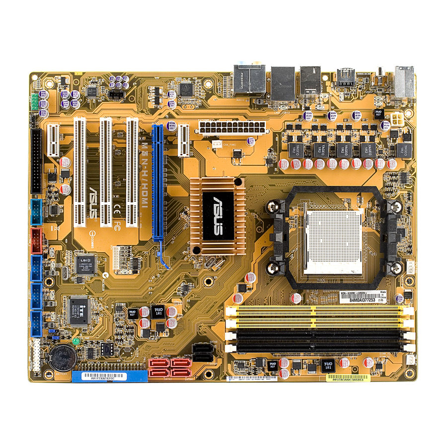
Page 26: Motherboard Overview
Motherboard overview Before you install the motherboard, study the configuration of your chassis to ensure that the motherboard fits into it. Make sure to unplug the power cord before installing or removing the motherboard. Failure to do so can cause you physical injury and damage motherboard components. -
Page 27: Motherboard Layout
BIOS PCI2 ® agere L-FW3227 ALC883 Super PCI3 SB_PWR Lithium Cell CHASSIS CMOS Power CLRTC PCIEX1_2 FLOPPY COM1 IE1394_2 USB78 USB910 USB1112 PANEL AAFP Refer to 2.7 Connectors for more information about rear panel connectors and internal connectors. ASUS M3N-H/HDMI... -
Page 28: Layout Contents
2.2.4 Layout contents Slots Page DDR2 DIMM slots 2-11 PCI slots 2-18 PCI Express x1 slots 2-18 PCI Express 2.0 x16 slot 2-19 Jumper Page Clear RTC RAM (3-pin CLRTC) 2-20 Rear panel connectors Page PS/2 keyboard port (purple) PS/2 keyboard port (purple) 2-21 IEEE 1394a port 2-21... - Page 29 Optical drive audio connector (4-pin CD) 2-33 Serial port connector (10-1 pin COM1) 2-33 Digital audio connector (4-1 pin SPDIF_OUT) 2-34 Video Graphics Adapter (VGA) connector (16-pin VGA) 2-34 System panel connector (20-8-pin PANEL) 2-35 ASUS Q-Connector (system panel) 2-36 ASUS M3N-H/HDMI...
-
Page 30: Central Processing Unit (Cpu)
Central Processing Unit (CPU) The motherboard comes with an AM2+/AM2 socket designed for AMD AM2+/AM2 socket designed for AMD socket designed for AMD Socket ® AM2+ Phenom™ FX / Phenom / Athlon™ / Sempron™ processors or for Socket Phenom™ FX / Phenom / Athlon™ / Sempron™ processors or for Socket AM2 Athlon series / Sempron processors. - Page 31 When the CPU is in place, push down the socket lever to secure the CPU. The lever clicks on the side tab to indicate that it is locked. Install a CPU heatsink and fan following the instructions that came with the heatsink package. ASUS M3N-H/HDMI...
-
Page 32: Installing The Heatsink And Fan
2.3.2 Installing the heatsink and fan The AMD Phenom™ FX / Phenom / Athlon™/ Sempron™ processor requires a Phenom™ FX / Phenom / Athlon™/ Sempron™ processor requires a processor requires a ® specially designed heatsink and fan assembly to ensure optimum thermal condition and performance. - Page 33 Push down the retention bracket lock on the retention mechanism to secure the heatsink and fan to the module base. ASUS M3N-H/HDMI...
- Page 34 When the fan and heatsink assembly is in place, connect the CPU fan cable to the connector on the motherboard labeled CPU_FAN. CPU_FAN M3N-H/HDMI ® M3N-H/HDMI CPU fan connector • Do not forget to connect the CPU fan connector! Hardware monitoring errors can occur if you fail to plug this connector.
-
Page 35: System Memory
The motherboard comes with four Double Data Rate 2 (DDR2) Dual Inline Memory Modules (DIMM) sockets. The figure illustrates the location of the DDR2 DIMM sockets: M3N-H/HDMI ® M3N-H/HDMI 240-pin DDR2 DIMM sockets Channel Sockets Channel A DIMM_A1 and DIMM_A2 Channel B DIMM_B1 and DIMM_B2 ASUS M3N-H/HDMI 2-11... -
Page 36: Memory Configurations
2.4.2 Memory configurations You may install 512 MB, 1 GB, and 2 GB unbuffered ECC and non-ECC DDR2 DIMMs into the DIMM sockets. Recommended Memory Configurations Sockets Mode DIMM_A1 DIMM_A2 DIMM_B1 DIMM_B2 (yellow) (black) (yellow) (black) – – Populated – Single-Channel Populated –... - Page 37 NANYA NT5TU64M8BE-25C NANYA NT1GT64U8HB0BY-25C • • NANYA NT5TU64M8CE-25D NANYA NT1GT64U8HCOBY-25D • • 512MB A3R12E3HEF641B9A05 AL6E8E63B8E1K • • • A3R12E3HEF641B9A05 AL7E8E63B-8E1K • • • 256MB TwinMOS E2508AB-GE-E ELPIDA 8G-24IK2-EBT • • Elixir N2TU51280BE-25C Elixir M2Y1G64TU8HB0B-25C • • • ASUS M3N-H/HDMI 2-13...
- Page 38 M3N-H/HDMI Motherboard Qualified Vendors Lists (QVL) DDR2-667MHz capability for AM2 CPU DIMM socket support (Optional) Chip Size Vendor Chip No. Part No. Brand 512MB KINGSTON D6408TEBGGL3U KINGSTON KVR667D2N5/512 • • • 256MB KINGSTON HYB18T256800AF3S KVR667D2N5/256 • 256MB KINGSTON 6SBI2D9DCG MICRON KVR667D2N5/256 •...
- Page 39 Dual-channel memory configuration. • C*: Supports four modules inserted into both the yellow slots and the black slots as two pairs of Dual-channel memory configuration. Visit the ASUS website for the latest QVL. ASUS M3N-H/HDMI 2-15...
-
Page 40: Installing A Dimm
2.4.3 Installing a DIMM Unplug the power supply before adding or removing DIMMs or other system components. Failure to do so can cause severe damage to both the motherboard and the components. To install a DIMM: DDR2 DIMM notch Unlock a DIMM socket by pressing the retaining clips outward. -
Page 41: Expansion Slots
When using PCI cards on shared slots, ensure that the drivers support “Share IRQ” or that the cards do not need IRQ assignments; otherwise, conflicts will arise between the two PCI groups, making the system unstable and the card inoperable. ASUS M3N-H/HDMI 2-17... -
Page 42: Interrupt Assignments
2.5.3 Interrupt assignments Standard interrupt assignments Priority Standard function System Timer Keyboard Controller – Redirect to IRQ#9 Communications Port (COM1)* IRQ Holder for PCI Steering* Floppy Disk Controller Reserved System CMOS/Real Time Clock IRQ Holder for PCI Steering* IRQ Holder for PCI Steering* IRQ Holder for PCI Steering* Reserved Numeric Data Processor... -
Page 43: Pci Express 2.0 X16 Slot
Hybrid Power function under Hybrid SLI™ mode. • Use only the onboard HDMI/DVI/D-Sub port for video signal output when activating the Hybird Power function under Hybrid SLI™ mode. • Visit www.nvidia.com/hybridsli for more information about Hybrid SLI™ support. ASUS M3N-H/HDMI 2-19... -
Page 44: Jumper
Jumper Clear RTC RAM (3-pin CLRTC) This jumper allows you to clear the Real Time Clock (RTC) RAM in CMOS. You can clear the CMOS memory of date, time, and system setup parameters by erasing the CMOS RTC RAM data. The onboard button cell battery powers the RAM data in CMOS, which include system setup information such as system passwords. -
Page 45: Connectors
Side Speaker Out port (gray). This port connects the side speakers in an 8-channel audio configuration. Refer to the audio configuration table on the next page for the function of the audio ports in 2, 4, 6, or 8-channel configuration. ASUS M3N-H/HDMI 2-21... - Page 46 Audio 2, 4, 6, or 8-channel configuration Headset Port 4-channel 6-channel 8-channel 2-channel Light Blue Line In Line In Line In Line In Lime Line Out Front Speaker Out Front Speaker Out Front Speaker Out Pink Mic In Mic In Mic In Mic In Orange...
-
Page 47: Troubleshooting On Hdtv Overscaling Or Underscaling
Click OK to exit. The Resize my desktop function in the NVIDIA Control Panel appears only when you are using an HDTV compliance resolution such as 480i, 720i, or 1080i. ASUS M3N-H/HDMI 2-23... -
Page 48: Internal Connectors
2.7.2 Internal connectors Floppy disk drive connector (34-1 pin FLOPPY) This connector is for the provided floppy disk drive (FDD) signal cable. Insert one end of the cable to this connector, then connect the other end to the signal connector at the back of the floppy disk drive. Pin 5 on the connector is removed to prevent incorrect cable connection when using a FDD cable with a covered Pin 5. -
Page 49: Ide Connector (40-1 Pin Pri_Ide)
Ultra DMA cable connector. This prevents incorrect insertion when you connect the IDE cable. • Use the 80-conductor IDE cable for Ultra DMA 133/100/66/33 IDE devices. If any device jumper is set as “Cable-Select,” make sure all other device jumpers have the same setting. ASUS M3N-H/HDMI 2-25... - Page 50 NVIDIA GeForce 8300 Serial ATA connectors (7-pin SATA1-6) ® These connectors are for the Serial ATA signal cables for Serial ATA hard disk and optical disk drives. If you install SATA hard disk drives to the SATA connectors, you can create a RAID 0, RAID 1, RAID 0+1, RAID 5, or JBOD configuration through the onboard NVIDIA GeForce 8300 controller.
- Page 51 Never connect a 1394 cable to the USB connectors. Doing so will damage the motherboard! You can connect the front panel USB cable to the ASUS Q-Connector (USB, blue) first, and then install the Q-Connector (USB) to the USB connector onboard if your chassis supports front panel USB ports.
- Page 52 Never connect a USB cable to the IEEE 1394a connector. Doing so will damage the motherboard! You can connect the front panel 1394 cable to the ASUS Q-Connector (1394, red) first, and then install the Q-Connector (1394) to the 1394 connector onboard if your chassis supports front panel 1394 ports.
- Page 53 These are not jumpers! Do not place jumper caps on the fan connectors! CPU_FAN PWR_FAN CHA_FAN1 +12V Rotation M3N-H/HDMI ® M3N-H/HDMI Fan connectors Only the CPU_FAN and CHA_FAN 1 connectors support the ASUS Q FAN2 feature. ASUS M3N-H/HDMI 2-29...
-
Page 54: Chassis Intrusion Connector (4-1 Pin Chassis)
Chassis intrusion connector (4-1 pin CHASSIS) This connector is for a chassis-mounted intrusion detection sensor or switch. Connect one end of the chassis intrusion sensor or switch cable to this connector. The chassis intrusion sensor or switch sends a high-level signal to this connector when a chassis component is removed or replaced. -
Page 55: Atx Power Connectors (24-Pin Eatxpwr; 4-Pin Atx12V)
• If you are uncertain about the minimum power supply requirement for your system, refer to the Recommended Power Supply Wattage Calculator at http://support.asus.com/PowerSupplyCalculator/PSCalculator. aspx?SLanguage=en-us for details. • The ATX 12 V Specification 2.0-compliant (500W) PSU has been tested... -
Page 56: Front Panel Audio Connector (10-1 Pin Aafp)
Front panel audio connector (10-1 pin AAFP) This connector is for a chassis-mounted front panel audio I/O module that supports either HD Audio or legacy AC`97 audio standard. Connect one end of the front panel audio I/O module cable to this connector. AAFP PIN 1 PIN 1... -
Page 57: Optical Drive Audio Connector (4-Pin Cd)
This connector is for a serial (COM) port. Connect the serial port module cable to this connector, then install the module to a slot opening at the back of the system chassis. COM1 M3N-H/HDMI ® M3N-H/HDMI Serial port (COM1) connector The COM module is purchased separately. ASUS M3N-H/HDMI 2-33... -
Page 58: Digital Audio Connector (4-1 Pin Spdif_Out)
12. Digital audio connector (4-1 pin SPDIF_OUT) This connector is for an additional Sony/Philips Digital Interface (S/PDIF) port(s). Connect the S/PDIF Out module cable to this connector, then install the module to a slot opening at the back of the system chassis. M3N-H/HDMI ®... -
Page 59: System Panel Connector
BIOS settings. Pressing the power switch for more than four seconds while the system is ON turns the system OFF. • Reset button (2-pin RESET) This 2-pin connector is for the chassis-mounted reset button for system reboot without turning off the system power. ASUS M3N-H/HDMI 2-35... -
Page 60: Asus Q-Connector (System Panel)
15. ASUS Q-Connector (system panel) You can use the ASUS Q-Connector to connect/disconnect chassis front panel cables in a few steps. Refer to the instructions below to install the ASUS Q-Connector. Connect the front panel cables to the ASUS Q-Connector. -
Page 61: Chapter 3: Powering Up
This chapter describes the power up sequence, the vocal POST messages, Chapter 3: and ways of shutting down the system. Powering up... - Page 62 Chapter summary Starting up for the first time ............3-1 Turning off the computer ............. 3-2 ASUS M3N-H/HDMI...
-
Page 63: Starting Up For The First Time
Check the jumper settings and connections or call your retailer for assistance. At power on, hold down the <Delete> key to enter the BIOS Setup. Follow the instructions in Chapter 4. ASUS M3N-H/HDMI... -
Page 64: Turning Off The Computer
Turning off the computer 3.2.1 Using the OS shut down function ® If you are using Windows Click the Start button then select Turn Off Computer. Click the Turn Off button to shut down the computer. ® The power supply should turn off after Windows shuts down. -
Page 65: Chapter 4: Bios Setup
This chapter tells how to change the system settings through the BIOS Setup menus. Detailed descriptions of the BIOS Chapter 4: parameters are also provided. BIOS setup... - Page 66 Chapter summary Managing and updating your BIOS ..........4-1 BIOS setup program ..............4-9 Main menu .................. 4-13 Advanced menu ................. 4-18 Power menu ................4-27 Boot menu .................. 4-31 Tools menu ................. 4-35 Exit menu ..................4-37 ASUS M3N-H/HDMI...
-
Page 67: Managing And Updating Your Bios
ASUS Update (Updates the BIOS in Windows environment.) ® ASUS EZ Flash 2 (Updates the BIOS using a floppy disk or USB flash disk.) ASUS AFUDOS (Updates the BIOS using a bootable floppy disk.) Refer to the corresponding sections for details on these utilities. - Page 68 To update the BIOS through the Internet: desktop by clicking Start Launch the ASUS Update utility from the Windows ® > Programs > ASUS > ASUSUpdate > ASUSUpdate. The ASUS Update main window appears. Select Update BIOS from the Select the ASUS FTP site nearest...
- Page 69 To update the BIOS through a BIOS file: Launch the ASUS Update utility from the Windows desktop by clicking Start ® > Programs > ASUS > ASUSUpdate > ASUSUpdate. The ASUS Update main window appears. Select Update BIOS from a file option from the drop-down menu, then click Next.
-
Page 70: Creating A Bootable Floppy Disk
4.1.2 Creating a bootable floppy disk Do either one of the following to create a bootable floppy disk. DOS environment a. Insert a 1.44MB floppy disk into the drive. b. At the DOS prompt, type format A:/S then press <Enter>. Windows XP environment ®... -
Page 71: Asus Ez Flash 2 Utility
4.1.3 ASUS EZ Flash 2 utility The ASUS EZ Flash 2 feature allows you to update the BIOS without having to go through the long process of booting from a floppy disk and using a DOS-based utility. The EZ Flash 2 utility is built-in the BIOS chip so it is accessible by pressing <Alt>... -
Page 72: Updating The Bios
The Basic Input/Output System (BIOS) can be updated using the AwardBIOS Flash Utility. Follow these instructions to update the BIOS using this utility. Visit the ASUS website (www.asus.com) and download the latest BIOS file for the motherboard. Save the BIOS file to a bootable floppy disk. - Page 73 Type the BIOS file name in AwardBIOS Flash Utility for ASUS V1.33 the File Name to Program (C) Phoenix Technologies Ltd. All Rights Reserved field, then press <Enter>. For MCP78-M3N-H-00 DATE:01/08/2008 Flash Type - File Name to Program: M3N-H.bin Message: Do You Want To Save Bios (Y/N) Press <N>...
-
Page 74: Saving The Current Bios File
To save the current BIOS file using the AwardBIOS Flash Utility: Follow steps 1 to 6 of the AwardBIOS Flash Utility for ASUS V1.33 previous section. (C) Phoenix Technologies Ltd. All Rights Reserved For MCP78-M3N-H-00 DATE:01/08/2008 Press <Y>... -
Page 75: Bios Setup Program
The BIOS setup screens shown in this section are for reference purposes only, and may not exactly match what you see on your screen. • Visit the ASUS website (www.asus.com) to download the latest BIOS file for this motherboard. ASUS M3N-H/HDMI... -
Page 76: Bios Menu Screen
The BIOS setup screens shown in this chapter are for reference purposes only, and may not exactly match what you see on your screen. • Visit the ASUS website (www.asus.com) to download the latest BIOS information. 4-10 Chapter 4: BIOS setup... -
Page 77: Legend Bar
A configurable field is enclosed in brackets, and is highlighted when selected. To change the value of a field, select it then press <Enter> to display a list of options. Refer to 4.2.7 Pop-up window. ASUS M3N-H/HDMI 4-11... -
Page 78: Pop-Up Window
Legacy Diskette A: [1.44M, 3.5 in.] Specifies the capacity Legacy Diskette A: Primary IDE Master [ST321122A] and physical size of Primary IDE Slave [ASUS CDS520/A] diskette drive A. SATA1 [None] Disabled ..[ ] SATA3 [None] 720K , 3.5 in. -
Page 79: Main Menu
Allows you to set the system time. 4.3.2 System Date [Day xx/xx/xxxx] Allows you to set the system date. 4.3.3 Legacy Diskette A [1.44M, 3.5 in.] Sets the type of floppy drive installed. Configuration options: [Disabled] [720K , 3.5 in.] [1.44M, 3.5 in.] ASUS M3N-H/HDMI 4-13... -
Page 80: Primary Ide Master/Slave
4.3.4 Primary IDE Master/Slave While entering Setup, the BIOS automatically detects the presence of IDE devices. There is a separate sub-menu for each IDE device. Select a device item then press <Enter> to display the IDE device information. Phoenix-Award BIOS CMOS Setup Utility Main Primary IDE Master Select Menu... - Page 81 FDISK, to partition and format new IDE hard disk drives. This is necessary so that you can write or read data from the hard disk. Make sure to set the partition of the Primary IDE hard disk drives to active. ASUS M3N-H/HDMI 4-15...
-
Page 82: Sata1/2/3/4
4.3.5 SATA1/2/3/4 While entering Setup, the BIOS automatically detects the presence of Serial ATA devices. There is a separate sub-menu for each SATA device. Select a device item then press <Enter> to display the SATA device information. Phoenix-Award BIOS CMOS Setup Utility Main SATA1 Select Menu... -
Page 83: Hdd Smart Monitoring
Technology (SMART) feature. Configuration options: [Disabled] [Enabled] 4.3.7 Installed Memory [xxx MB] Shows the size of installed memory. This item is not configurable. 4.3.8 Usable Memory [XXX MB] Shows the size of usable memory. This item is not configurable. ASUS M3N-H/HDMI 4-17... -
Page 84: Advanced Menu
Advanced menu The Advanced menu items allow you to change the settings for the CPU and other system devices. Take caution when changing the settings of the Advanced menu items. Incorrect field values can cause the system to malfunction. The configuration options for the Advanced menu items vary depending on the CPU and DIMMs you install on the motherboard. - Page 85 This item becomes user-configurable only when you set the AI Tuning item to [Manual] and is adjusted by typing the desired values using the numeric keypad and press the <Enter> key. The values range from 100 to 200. The values range from 100 to 200. ASUS M3N-H/HDMI 4-19...
-
Page 86: Ai Net 2
4.4.2 Ai Net 2 This menu displays the status of the Local Area Network (LAN) cable connected to the LAN (RJ-45) port. Phoenix-Award BIOS CMOS Setup Utility Advanced AI NET 2 Select Menu Item Specific Help POST Check LAN Cable [Disabled] Enable or Disable LAN Pair... -
Page 87: Chipset
PCIE Spread Spectrum [Disabled] SATA Spread Spectrum [Disabled] Primary Display Adapter [PCI-E] Hybrid Support [Disable] Allows you to enable or disable the Hybrid SLI function if you install a Hybrid SLI- support graphics card. Configuration options: [Enable] [Disable]. ASUS M3N-H/HDMI 4-21... - Page 88 iGPU Frame Buffer Control [Auto] Allows you to set the onboard GPU frame buffer control mode. Configuration options: [Auto] [Manual] Frame Buffer Size [128M] This item becomes user-configurable when you set the iGPU Frame Buffer Control item to [Manual] and allows you to set frame buffer size for onboard GPU. Configuration options: [64M] [128M] [256M] [512M] •...
-
Page 89: Pcipnp
[PCI Device] compliant with the IRQ-10 assigned to [PCI Device] original PC AT bus IRQ-11 assigned to [PCI Device] specification, PCI/ IRQ-14 assigned to [PCI Device] ISA PnP for devices compliant with the Plug and Play standard ASUS M3N-H/HDMI 4-23... -
Page 90: Onboard Device Configuration
IRQ-xx assigned to [PCI Device] When set to [PCI Device], the specific IRQ is free for use of PCI/PnP devices. When set to [Reserved], the IRQ is reserved for legacy ISA devices. Configuration options: [PCI Device] [Reserved] Maximum Payload Size [4096] Sets maximum TLP payload size for the PCI Express devices. -
Page 91: Mcp Storage Config
Configuration options: [AC97] [HD Audio] HDMI Audio [Auto] Allows you to disable or enable the HDMI Audio function. Configuration options: [Auto] [Disabled] ASUS M3N-H/HDMI 4-25... -
Page 92: Usb Configuration
Make sure to set the HDMI Audio item to [Auto] to enable HDMI audio output. Onboard LAN Device [Enabled] Allows you to enable or disable the OnBoard LAN device. Configuration options: [Disabled] [Enabled] Onboard LAN Boot ROM [Disabled] Allows you to enable or disable the OnBoard LAN Boot ROM. Configuration options: [Enabled] [Disabled] Serial Port1 Address [3F8/IRQ4] Allows you to select the Serial Port1 base address. -
Page 93: Power Menu
AC power loss HPET Support [Enabled] Power On By PS/2 Keyboard [Disabled] Restore on AC Power Loss [Power-Off] Allows you to enable or disable the Restore on AC Power Loss function. Configuration options: [Power-Off] [Power-On] [Last State] ASUS M3N-H/HDMI 4-27... - Page 94 PWR Button < 4 secs [Instant-Off] When set to [Instant-Off], the system goes into Soft-off mode after you press the power button for less than 4 seconds. When set to [Suspend], the system goes into Suspend mode after you press the power button for less than 4 seconds. Configuration options: [Suspend] [Instant-Off] Power Up On PCI/PCIE Devices [Disabled] Allows you to enable or disable the PME to wake up from S5 by PCI/PCIE devices...
-
Page 95: Hardware Monitor
Control function will not work and the fan you install will always run at full speed. CPU Q-Fan Control [Disabled] Allows you to enable or disable the CPU Q-Fan controller. Configuration options: [Disabled] [Enabled] The CPU Q-Fan Profile item becomes user-configurable when you enable the CPU Q-Fan Control feature. ASUS M3N-H/HDMI 4-29... - Page 96 CPU Q-Fan Profile [Performance] Allows you to set the appropriate performance level of the CPU Q-Fan. When set to [Optimal], the CPU fan automatically adjusts depending on the CPU temperature. Set this item to [Silent] to minimize fan speed for quiet CPU fan operation, or [Performance] to achieve maximum CPU fan speed.
-
Page 97: Boot Menu
Configuration options: [Removable] [Hard Disk] [CDROM] [Disabled] 4.6.2 Removable Drives Phoenix-Award BIOS CMOS Setup Utility Boot Removable Drives Select Menu 1. Floppy Disks Item Specific Help 1. Floppy Disks Allows you to assign a removable drive attached to the system. ASUS M3N-H/HDMI 4-31... -
Page 98: Boot Settings Configuration
4.6.3 Boot Settings Configuration Phoenix-Award BIOS CMOS Setup Utility Boot Boot Settings Configuration Select Menu Case Open Warning [Enabled] Item Specific Help Quick Boot [Enabled] Allows the system to Boot Up Floppy Seek [Disabled] skip certain tests Bootup Num-Lock [On] while booting. -
Page 99: Security
This allows you to enable or disable the full screen logo display feature. Configuration options: [Disabled] [Enabled] Set this item to [Enabled] to use the ASUS MyLogo 2™ feature. Halt On [All Errors] Allows you to set the error report type. -
Page 100: Password Check
Press any key to continue. The password field setting is changed to [Clear]. A note about passwords The Supervisor password is required to enter the BIOS Setup program preventing unauthorized access. The User password is required to boot the system preventing unauthorized use. Forgot your password? If you forget your password, you can clear it by erasing the CMOS Real Time Clock (RTC) RAM. -
Page 101: Tools Menu
F10: Save and Exit 4.7.1 ASUS EZ Flash 2 Allows you to run ASUS EZ Flash 2. When you press <Enter>, a confirmation message appears. Use the left/right arrow key to select between [Yes] or [No], then press <Enter> to confirm your choice. -
Page 102: Express Gate Lite
[No] Express Gate Lite [Enabled] Allows you to enable or disable the ASUS Express Gate Lite feature. The ASUS Express Gate Lite is a unique instant-on environment that provides quick access to the Internet browser and Skype. Refer to section 5.3.10 ASUS Express Gate Lite for details. -
Page 103: Exit Menu
Discard Changes This option allows you to discard the selections you made and restore the previously saved values. After selecting this option, a confirmation appears. Select YES to discard any changes and load the previously saved values. ASUS M3N-H/HDMI 4-37... - Page 104 4-38 Chapter 4: BIOS setup...
-
Page 105: Chapter 5: Software Support
This chapter describes the contents of the support DVD that comes with the motherboard package. Chapter 5: Software support... - Page 106 Chapter summary Installing an operating system ........... 5-1 Support DVD information ............5-1 Software information ..............5-9 RAID configurations ..............5-37 Creating a RAID driver disk ............5-45 ASUS M3N-H/HDMI...
-
Page 107: Installing An Operating System
The contents of the support DVD are subject to change at any time without notice. Visit the ASUS website(www.asus.com) for updates. 5.2.1 Running the support DVD Place the support DVD to the optical drive. The DVD automatically displays the Drivers menu if Autorun is enabled in your computer. -
Page 108: Drivers Menu
The drivers menu shows the available device drivers if the system detects installed devices. Install the necessary drivers to activate the devices. ASUS InstAll - Installation Wizard for Drivers Installs all of the drivers through the installation wizard. NVIDIA Chipset Driver Program ®... -
Page 109: Utilities Menu
Click to return to the previous page ASUS InstAll - Installation Wizard for Utilities Installs all of the utilities through the Installation Wizard. ASUS PC Probe II This smart utility monitors the fan speed, CPU temperature, and system voltages, and alerts you of any detected problems. - Page 110 ASUS Update Allows you to download the latest version of the BIOS from the ASUS website. Before using the ASUS Update, make sure that you have an Internet connection so you can connect to the ASUS website. ASUS Cool‘n’Quiet Utility This item installs the ASUS Cool‘n’Quiet utility.
-
Page 111: Make Disk Menu
Vista, please install the AHCI/RAID driver through the motherboard ® support DVD/DVD or a USB device. Find RAID driver in the support DVD/DVD through the path below: Drivers\Chipset\Disk\RAID Find AHCI driver in the support DVD/DVD through the path below: Drivers\Chipset\Disk\AHCI ASUS M3N-H/HDMI... -
Page 112: Manual Menu
Reader from the Utilities menu before opening a user manual ® ® file. 5.2.6 ASUS Contact information Click the Contact tab to display the ASUS contact information. You can also find this information on the inside front cover of this user guide. Chapter 5: Software support... -
Page 113: Other Information
The icons on the top right corner of the screen give additional information on the motherboard and the contents of the support DVD. Click an icon to display the specified information. Motherboard Info Displays the general specifications of the motherboard. Browse this DVD Displays the support DVD contents in graphical format. ASUS M3N-H/HDMI... -
Page 114: Technical Support Form
Technical support Form Displays the ASUS Technical Support Request Form that you have to fill out when requesting technical support. File list Displays the contents of the support DVD and a brief description of each in text format. Chapter 5: Software support... -
Page 115: Software Information
5.3.1 ASUS MyLogo2™ The ASUS MyLogo2™ utility lets you customize the boot logo. The boot logo is the image that appears on screen during the Power-On Self-Tests (POST). The ASUS MyLogo2™ is automatically installed when you install the ASUS Update utility from the support DVD. - Page 116 Ratio box. When the screen returns to the ASUS Update utility, flash the original BIOS to load the new boot logo. 10. After flashing the BIOS, restart the computer to display the new boot logo during POST.
-
Page 117: Cool 'N' Quiet!™ Technology
Double-click the Display icon in the Control Panel then select the Screen Saver tab. Click the Power button. The following dialogue box appears. From the Power schemes combo list box, select Minimal Power Management. Click OK to effect settings. ASUS M3N-H/HDMI 5-11... - Page 118 The AMD Cool ‘n’ Quiet!™ technology feature works only with the AMD heatsink and fan assembly with monitor chip • If you purchased a separate heatsink and fan package, use the ASUS Q-Fan technology feature to automatically adjust the CPU fan speed according to your system loading.
- Page 119 If you are using Windows Vista, click the Start button. Select All Programs ® > ASUS > Cool & Quiet > Cool & Quiet. The Cool ‘n’ Quiet!™ technology screen appears and displays the current CPU Frequency and CPU Voltage.
-
Page 120: Audio Configurations
5.3.3 Audio configurations The Realtek ALC1200 audio CODEC provides 8-channel audio capability to ® deliver the ultimate audio experience on your computer. The software provides Jack-Sensing function, S/PDIF Out support, and interrupt capability. The ALC1200 also includes the Realtek proprietary UAJ (Universal Audio Jack) technology for ®... -
Page 121: Configuration Options
Manager, click the Sound Effect tab. Click the shortcut buttons or the drop-down menus for options on changing the acoustic environment, adjust the equalizer, or set the karaoke to your desired settings. Click to effect the Sound Effect settings and exit. ASUS M3N-H/HDMI 5-15... - Page 122 Mixer The Mixer option allows you to configure audio output (playback) volume and audio input (record) volume. To set the mixer options: From the Realtek HD Audio Manager, click the Mixer tab. Turn the volume buttons to adjust the Playback and/or Record volume.
- Page 123 From the Realtek HD Audio Manager, click the 3D Audio Demo tab. Click the option buttons to change the sound, moving path, or environment settings. Click to test your settings. Click to effect the 3D Audio Demo settings and exit. ASUS M3N-H/HDMI 5-17...
-
Page 124: Asus Pc Probe Ii
To launch the PC Probe II from the Windows desktop, click Start > All Programs ® > ASUS > PC Probe II > PC Probe II v1.xx.xx. The PC Probe II main window appears. After launching the application, the PC Probe II icon appears in the Windows ®... - Page 125 When displayed, the monitor panel for that sensor also turns red. Refer to the Monitor panels section for details. Preference You can customize the application using the Preference section in the main window. Click the box before each preference to activate or deactivate. ASUS M3N-H/HDMI 5-19...
- Page 126 Hardware monitor panels The hardware monitor panels display the current value of a system sensor such as fan rotation, CPU temperature, and voltages. The hardware monitor panels come in two display modes: hexagonal (large) and rectangular (small). When you check the Enable Monitoring Panel option from the Preference section, the monitor panels appear on your computer’s desktop.
- Page 127 You can enlarge or reduce the browser size by dragging the bottom right corner of the browser. DMI browser Click to display the DMI (Desktop Management Interface) browser. This browser displays various desktop and system information. Click the plus sign (+) before DMI Information to display the available information. ASUS M3N-H/HDMI 5-21...
- Page 128 PCI browser Click to display the PCI (Peripheral Component Interconnect) browser. This browser provides information on the PCI devices installed on your system. Click the plus sign (+) before the PCI Information item to display available information. Usage The Usage browser displays real-time information on the CPU, hard disk drive space, and memory usage.
- Page 129 The Preference tab allows you to customize sensor alerts, or change the temperature scale. Loads the default Loads your saved threshold values for Cancels or configuration each sensor ignores your changes Applies your Saves your changes configuration ASUS M3N-H/HDMI 5-23...
-
Page 130: Asus Ai Suite
5.3.5 ASUS AI Suite ASUS AI Suite allows you to launch AI Gear 2, AI Booster, AI Nap, and Q-Fan 2 utilities easily. Installing AI Suite To install AI Suite on your computer: Place the support DVD to the optical drive. The Drivers installation tab appears if your computer has an enabled Autorun feature. - Page 131 Displays the CPU/ system temperature, CPU/memory/PCIE voltage, and CPU/ chassis fan speed Displays the FSB/CPU frequency Click on right corner of the expanded window to switch the temperature from degrees Centigrade to degrees Fahrenheit. ASUS M3N-H/HDMI M3N-H/HDMI 5-25...
-
Page 132: Asus Ai Gear 2
5.3.6 ASUS AI Gear 2 ASUS AI Gear 2 provides four system performance options that allows you to select the best performance setting for your computing needs. This easy-to-use utility adjusts the processor frequency and vCore voltage to minimize system noise and power consumption. -
Page 133: Asus Ai Nap
5.3.7 ASUS AI Nap This feature allows you to minimize the power consumption of your computer whenever you are away. Enable this feature for minimum power consumption and a more quiet system operation. After installing AI Suite from the bundled support DVD, you can launch the utility by double-clicking the AI Suite icon on the Windows OS taskbar and click the AI Nap button on the AI Suite main window. -
Page 134: Asus Q-Fan 2
5.3.8 ASUS Q-Fan 2 This ASUS Q-Fan 2 Control feature allows you to set the appropriate performance level of the CPU Q-Fan 2 or the Chassis Q-Fan 2 for more efficient system operation. After enabling the Q-Fan 2 function, the fans can be set to automatically adjust depending on the temperature, to decrease fan speed, or to achieve the maximum fan speed. -
Page 135: Asus Ai Booster
5.3.9 ASUS AI Booster The ASUS AI Booster application allows you to overclock the CPU speed in WIndows environment without the hassle of booting the BIOS. ® After installing AI Suite from the bundled support DVD, you can launch the utility... -
Page 136: Asus Express Gate Lite
5.3.10 ASUS Express Gate Lite ASUS Express Gate Lite is an instant-on environment that gives you quick access to the Internet. Within a few seconds of powering on your computer, you will be at the Express Gate Lite menu where you can start the web browser, Skype, or other Express Gate Lite softwares. - Page 137 The red triangle on an software icon in the LaunchBar denotes that the software is already running. This means that you can switch to it without any delay. In the rare case where an software stops responding, right-click on its icon to force close it. ASUS M3N-H/HDMI M3N-H/HDMI 5-31...
-
Page 138: Using The Configuration Panel
Using the Configuration Panel Use the configuration panel to change various Express Gate Lite settings. Click on an icon to open a particular configuration tool. The following tools are available: Date and Time: set current date and time as well as time zone. •... -
Page 139: Using The Launchbar
USB drive. If a USB device is detected, the icon contains a green arrow. ASUS Express Gate Lite supports file uploading and downloading on USB drives in FAT16/32 format only. Shows network status; click to configure network. - Page 140 Click to show “About Express Gate Lite”. Click to open Express Gate Lite Help. Click to bring up power options window to boot to OS, restart or power down. This window is also shown when you press Ctrl-Alt-Del on the keyboard.
- Page 141 LAN port. Then enter the username and password for your dial-up account. Click OK to enable xDSL/cable dial-up and establish the PPPoE connection. When PPPoE is enabled, the port it uses will automatically be unchecked and grayed out. ASUS M3N-H/HDMI M3N-H/HDMI 5-35...
- Page 142 Express Gate Lite software will be released regularly, adding refinements or new applications. You can find original version of the software on the support DVD or download new versions from the ASUS support website. To update Express Gate Lite: Double-click the Express Gate Lite setup file to start software update.
-
Page 143: Raid Configurations
RAID set, first copy the RAID driver from the support DVD to a floppy disk before you install an operating system to a selected hard disk drive. Refer to section 5.5 Creating a RAID driver disk for details. ASUS M3N-H/HDMI 5-37... -
Page 144: Nvidia ® Raid Configurations
5.4.2 NVIDIA RAID configurations ® The motherboard includes a high performance SATA RAID controller integrated in the NVIDIA GeForce 8300 chipset. It supports RAID 0, RAID 1, RAID 0+1, RAID 5 ® and JBOD for six independent Serial ATA channels. Installing Serial ATA (SATA) hard disks The motherboard supports Ultra DMA 133/100/66 and Serial ATA hard disk drives. -
Page 145: Entering The Nvidia Raid Utility
2.0.M XXXXXXXXXXXXXXXXXX 2.1.M XXXXXXXXXXXXXXXXXX [←] Del [F6] Back [F7] Finish [TAB] Navigate [↑↓] Select [ENTER] Popup At the bottom of the screen are the navigation keys. These keys allow you to move through and select menu options. ASUS M3N-H/HDMI 5-39... -
Page 146: Creating A Raid Volume
Creating a RAID Volume To create a RAID volume: From the NVIDIA RAID utility Define a New Array menu, select RAID Mode ® then press <Enter>. The following submenu appears. Use the up or down arrow keys to select a Mirroring RAID mode then press <Enter>. -
Page 147: Rebuilding A Raid Array
Array 1 : NVIDIA MIRROR XXX.XXG - Array Detail - RAID Mode: Mirroring Striping Width: 1 Striping Block: 64K Adapt Channel Index Disk Model Name Capacity Master XXXXXXXXXXXXXXXXX XXX.XXGB Master XXXXXXXXXXXXXXXXX XXX.XXGB [R] Rebuild [D] Delete [C] Clear Disk [ENTER] Return ASUS M3N-H/HDMI 5-41... - Page 148 A new set of navigation keys is displayed on the bottom of the screen. Press <R> to rebuild a RAID array. The following screen appears. Array 1 : NVIDIA MIRROR XXX.XXG - Select Disk Inside Array - RAID Mode: Mirroring Striping Width: 1 Striping Block: 64K Adapt...
-
Page 149: Deleting A Raid Array
[N] No Press <Y> to delete array or press <N> to cancel. Take caution in using this option. All data on the RAID drives will be lost! If you selected Yes, the Define a New Array menu appears. ASUS M3N-H/HDMI 5-43... -
Page 150: Clearing A Disk Data
Clearing a disk data To clear disk data: From the Array List menu, use the up or down arrow keys to select a RAID array then press <Enter>. The RAID Array details appear. Array 1 : NVIDIA MIRROR XXX.XXG - Array Detail - RAID Mode: Mirroring Striping Width: 1 Striping Block: 64K... -
Page 151: Creating A Raid Driver Disk
During the OS installation, the system prompts you to press the F6 key to install third-party SCSI or RAID driver. Press <F6> then insert the floppy disk with RAID driver into the floppy disk drive. Follow the succeeding screen instructions to complete the installation. ASUS M3N-H/HDMI 5-45... - Page 152 ® To install the RAID driver in Windows Vista™: Insert the motherboard support CD/DVD or USB device with RAID driver into the optical drive or USB port. Find RAID driver in the support CD/DVD through the path below: Drivers\Chipset\Disk\RAID Find AHCI driver in the support CD/DVD through the path below: Drivers\Chipset\Disk\AHCI Follow the succeeding screen instructions to complete the installation.
Need help?
Do you have a question about the M3N-H HDMI and is the answer not in the manual?
Questions and answers