Table of Contents
Advertisement
Advertisement
Table of Contents

Related Manuals for Asus M3N78 SE


Summary of Contents for Asus M3N78 SE
- Page 1 M3N78 SE...
- Page 2 Product warranty or service will not be extended if: (1) the product is repaired, modified or altered, unless such repair, modification of alteration is authorized in writing by ASUS; or (2) the serial number of the product is defaced or missing.
-
Page 3: Table Of Contents
Contents Notices ......................vi Safety information ..................vii About this guide ..................vii M3N78 SE specifications summary ............ix Chapter 1 :Product introduction Welcome! ..................1-1 Package contents ................. 1-1 Special features ................1-1 1.3.1 Product highlights ............1-1 1.3.2 Innovative ASUS features .......... - Page 4 2.1.1 Creating a bootable floppy disk ........2-1 2.1.2 ASUS Update utility ............2-2 2.1.3 ASUS EZ Flash 2 utility ........... 2-3 2.1.4 AFUDOS utility ..............2-4 2.1.5 ASUS CrashFree BIOS 3 utility ........2-5 BIOS setup program ..............2-6 2.2.1...
- Page 5 Boot menu .................. 2-20 2.6.1 Boot Device Priority ............2-20 2.6.2 Boot Settings Configuration .......... 2-20 2.6.3 Security ................. 2-21 Tools menu ................. 2-22 2.7.1 ASUS EZ Flash 2 ............2-22 2.7.2 AI NET 2................ 2-23 Exit menu ..................2-23...
-
Page 6: Notices
Notices Federal Communications Commission Statement This device complies with Part 15 of the FCC Rules. Operation is subject to the following two conditions: • This device may not cause harmful interference, and • This device must accept any interference received including interference that may cause undesired operation. -
Page 7: Safety Information
Safety information Electrical safety • To prevent electrical shock hazard, disconnect the power cable from the electrical outlet before relocating the system. • When adding or removing devices to or from the system, ensure that the power cables for the devices are unplugged before the signal cables are connected. If possible, disconnect all power cables from the existing system before you add a device. -
Page 8: Conventions Used In This Guide
Refer to the following sources for additional information and for product and software updates. ASUS websites The ASUS website provides updated information on ASUS hardware and software products. Refer to the ASUS contact information. Optional documentation Your product package may include optional documentation, such as warranty flyers, that may have been added by your dealer. -
Page 9: M3N78 Se Specifications Summary
2 x 240-pin DIMM slots support unbuffered ECC and non-ECC DDR2 1066/800/667/533MHz memory modules Supports up to 8GB system memory * Refer to www.asus.com for the latest Memory QVL (Qualified Vendors List). * When you install a total memory of 4GB or more, Windows 32-bit operation system may only recognize ®... - Page 10 24-pin EATX power connector 4-pin ATX 12V power connector BIOS 8Mb Flash ROM, AMI BIOS, PnP, DMI2.0, WfM2.0, ACPI2.0, SM BIOS 2.5, ASUS EZ Flash 2 Accessories 1 x Serial ATA cable 1 x Serial ATA power cable 1 x UltraDMA 133/100/66 cable...
-
Page 11: Chapter 1 :Product Introduction
® The motherboard delivers a host of new features and latest technologies, making it another standout in the long line of ASUS quality motherboards! Before you start installing the motherboard, and hardware devices on it, check the items in your package with the list below. - Page 12 NVIDIA nForce™ 720D chipset ® The NVIDIA nForce 720D supports HyperTransport™3.0 interface, ® PCI Express™ 2.0 bus architecture, and Serial ATA 3 GB/s devices. It is optimized with AMD’s latest AM2+ and multi-core CPUs to provide excellent system performance. HyperTransport 3.0 support 5200 HyperTransport 3.0 technology provides 2.6 times more bandwidth than MT/s...
-
Page 13: Innovative Asus Features
See page 2-20 for details. ASUS CrashFree BIOS 3 The ASUS CrashFree BIOS 3 allows you to restore corrupted BIOS data from a USB flash disk containing the BIOS file. This utility saves you the cost and hassle of buying a replacement BIOS chip. See page 2-5 for details. -
Page 14: Before You Proceed
The illustration below shows the location of the onboard LED. SB_PWR M3N78 SE Standy Power Powered Off M3N78 SE Onboard LED Chapter 1: Product introduction... -
Page 15: Motherboard Overview
Place six (6) screws into the holes indicated by circles to secure the motherboard to the chassis. Do not overtighten the screws! Doing so can damage the motherboard. Place this side towards the rear of the chassis. M3N78 SE ASUS M3N78 SE... -
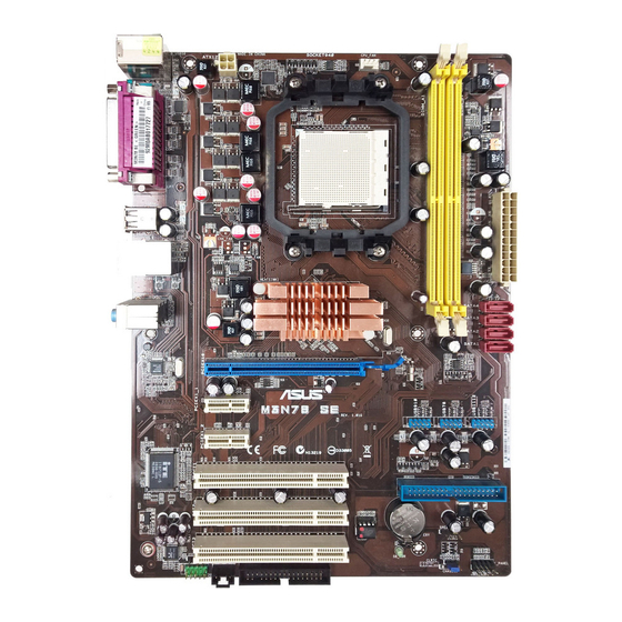
Page 16: Motherboard Layout
21.8cm(8.6in) CPU_FAN KB_USB56 ATX12V USB34 LAN1_USB12 NVIDIA ® SATA4 AUDIO MCP78D SATA3 SATA2 SATA1 Realtek PCIEX16 8211CL PCIEX1_1 M3N78 SE USB910 USB78 USB1112 PCIEX1_2 PCI1 PRI_IDE PCI2 Lithium Cell CMOS Power BIOS SPEAKER PCI3 SPDIF_OUT SB_PWR F_PANEL CLRTC FLOPPY AAFP 1.5.4... -
Page 17: Central Processing Unit (Cpu)
Installing the CPU To install a CPU: Locate the CPU socket on the motherboard. M3N78 SE M3N78 SE CPU socket 940 Unlock the socket by pressing the lever Socket lever sideways, then lift it up to a 90º angle. Make sure that the socket lever is lifted up to a 90º... - Page 18 Connect the CPU fan cable to the CPU_FAN connector on the motherboard. CPU_FAN Do not forget to connect the M3N78 SE CPU fan connector! Hardware monitoring errors can occur if you fail to plug this connector. M3N78 SE CPU fan connector Chapter 1: Product introduction...
-
Page 19: Installing The Heatsink And Fan
Your boxed CPU heatsink and fan assembly should come with installation instructions for the CPU, heatsink, and the retention mechanism. If the instructions in this section do not match the CPU documentation, follow the latter. Attach one end of the retention bracket to the retention module base. ASUS M3N78 SE... -
Page 20: System Memory
DDR DIMM socket. The figure illustrates the location of the DDR2 DIMM sockets: Channel Sockets Channel 1 DIMM_A1 Channel 2 DIMM_B1 M3N78 SE M3N78 SE 240-pin DDR2 DIMM sockets 1-10 Chapter 1: Product introduction... -
Page 21: Memory Configurations
OS can be about 3GB or less. For effective use of memory, we recommend that you install a 64-bit Windows OS when having 4GB or more memory installed on the motherboard. M3N78 SE Motherboard Qualified Vendors Lists (QVL) DDR2-533MHz capability DIMM support Vendor Part No. - Page 22 • A*: Supports one module inserted into any slot as Single-channel memory configuration. • B*: Supports one pair of modules inserted into the yellow slots as one pair of Dual-channel memory configuration. Visit the ASUS website for the latest DDR2-533/667/800/1066MHz QVL. 1-12 Chapter 1: Product introduction...
-
Page 23: Installing A Dimm
Simultaneously press the retaining clips outward to unlock the DIMM. Support the DIMM lightly with your fingers when pressing the retaining clips. The DIMM might get damaged when it flips out with extra force. DDR2 DIMM notch Remove the DIMM from the socket. ASUS M3N78 SE 1-13... -
Page 24: Expansion Slots
Expansion slots In the future, you may need to install expansion cards. The following sub-sections describe the slots and the expansion cards that they support. Ensure that you unplug the power cord before adding or removing expansion cards. Failure to do so may cause you physical injury and damage to the motherboard components. 1.8.1 Installing an expansion card To install an expansion card:... -
Page 25: Jumpers
Normal Clear RTC (Default) M3N78 SE Clear RTC RAM You do not need to clear the RTC when the system hangs due to overclocking. For system failure due to overclocking, use the CPU Parameter Recall (C.P.R) feature. Shut down and reboot the system so the BIOS can automatically reset parameter settings to default values. -
Page 26: Connectors
1.10 Connectors 1.10.1 Rear panel connectors PS/2 keyboard/Mouse Combo port (purple). This port is for a PS/2 keyboard or mouse. Parallel port. This 25-pin port connects a parallel printer, a scanner, or other devices. LAN (RJ-45) port. This port allows Gigabit connection to a Local Area Network (LAN) through a network hub. -
Page 27: Internal Connectors
FDD cable with a covered Pin 5. • The Floppy Disk Drive singal cable is purchased separately. FLOPPY M3N78 SE PIN1 NOTE:Orient the red markings on the floppy ribbon cable to PIN 1. M3N78 SE Floppy disk drive connector ASUS M3N78 SE 1-17... - Page 28 SPEAKER M3N78 SE PIN 1 M3N78 SE Speaker Out Connector IDE connector (40-1 pin PRI_IDE) The onboard IDE connector is for Ultra DMA 133/100/66 signal cable. There are three connectors on each Ultra DMA 133 / 100 / 66 signal cable: blue, black, and gray.
- Page 29 SATA4 SATA3 SATA2 M3N78 SE SATA1 M3N78 SE SATA connectors Important note on Serial ATA Install the Windows XP Service Pack 1 before using Serial ATA. ® • For detailed instructions on how to configure RAID 0, RAID 1, and RAID 0+1, RAID 5, and JBOD, refer to the RAID manual in the support DVD.
- Page 30 This connector allows you to receive stereo audio input from sound sources such as a CD-ROM, TV tuner, or MPEG card. M3N78 SE M3N78 SE Internal audio connector USB connectors (10-1 pin USB78, USB 910, USB1112) These connectors are for USB 2.0 ports. Connect the USB module cable to any of these connectors, then install the module to a slot opening at the back of the system chassis.
- Page 31 Legacy AC’97 pin definition compliant definition M3N78 SE Analog front panel connector • We recommend that you connect a high-definition front panel audio module to this connector to avail of the motherboard high-definition audio capability. • By default, this connector is set to [HD Audio]. If you want to connect a High Definition front panel audio module to this connector, set the Front Panel Select item in the BIOS to [HD Audio].
-
Page 32: Atx Power Connectors
• If you are uncertain about the minimum power supply requirement for your system, refer to the Recommended Power Supply Wattage Calculator at http://support.asus. com/PowerSupplyCalculator/PSCalculator.aspx?SLanguage=en-us for details. • You must install a PSU with a higher power rating if you intend to install additional devices. - Page 33 PIN 1 M3N78 SE HD_LED RESET M3N78 SE System panel connector System power LED (2-pin PWRLED) • This 2-pin connector is for the system power LED. Connect the chassis power LED cable to this connector. The system power LED lights up when you turn on the system power, and blinks when the system is in sleep mode.
-
Page 34: Software Support
The contents of the Support DVD are subject to change at any time without notice. Visit the ASUS website at www.asus.com for updates. To run the Support DVD: Place the Support DVD to the optical drive. -
Page 35: Creating A Raid Driver Disk
Press <F6> then insert the floppy disk with RAID driver into the floppy disk drive. Follow the succeeding screen instructions to complete the installation. Due to chipset limitation, the Serial ATA ports supported by the NVIDIA chipset does not support Serial Optical Disk Drives (Serial ODD) under DOS. ASUS M3N78 SE 1-25... - Page 36 1-26 Chapter 1: Product introduction...
-
Page 37: Chapter 2: Bios Information
Save a copy of the original motherboard BIOS file to a bootable floppy disk or a USB flash disk in case you need to restore the BIOS in the future. Copy the original motherboard BIOS using the ASUS Update or AFUDOS utilities. 2.1.1 Creating a bootable floppy disk Do either one of the following to create a bootable floppy disk. -
Page 38: Asus Update Utility
2.1.2 ASUS Update utility The ASUS Update is a utility that allows you to manage, save, and update the motherboard BIOS in Windows environment. ® • ASUS Update requires an Internet connection either through a network or an Internet Service Provider (ISP). -
Page 39: Asus Ez Flash 2 Utility
2.1.3 ASUS EZ Flash 2 utility The ASUS EZ Flash 2 feature allows you to update the BIOS without having to go through the long process of booting from a floppy disk or a DOS-based utility. Download the lates BIOS file from the ASUS website at www.asus.com. -
Page 40: Afudos Utility
• Obtain the AFUDOS utility (afudos.exe) from the bundled support DVD and the latest BIOS file from the ASUS website at www.asus.com. • We recommend that you write the BIOS filename on a piece of paper. You will need to key in the exact BIOS filename at the DOS prompt later. -
Page 41: Asus Crashfree Bios 3 Utility
2.1.5 ASUS CrashFree BIOS 3 utility The ASUS CrashFree BIOS 3 is an auto recovery tool that allows you to restore the BIOS file when it fails or gets corrupted during the updating process. You can update a corrupted BIOS file using the motherboard Support DVD, a floppy disk or a USB flash disk that contains the updated BIOS file. -
Page 42: Bios Setup Program
The BIOS setup screens shown in this section are for reference purposes only, and may not exactly match what you see on your screen. • Visit the ASUS website at www.asus.com to download the latest BIOS file for this motherboard. -
Page 43: Bios Menu Screen
• The BIOS setup screens shown in this chapter are for reference purposes only, and may not exactly match what you see on your screen. • Visit the ASUS website at www.asus.com to download the latest BIOS information. ASUS M3N78 SE... -
Page 44: Navigation Keys
2.2.3 Navigation keys At the bottom right corner of a menu screen are the navigation keys for that particular menu. Use the navigation keys to select items in the menu and change the settings. Some of the navigation keys differ from one screen to another. 2.2.4 Menu items The highlighted item on the menu bar displays the specific items for that menu. -
Page 45: Main Menu
IDE device type. Select [CDROM] if you are specifically configuring a CD-ROM drive. Select [ARMD] (ATAPI Removable Media Device) if your device is either a ZIP, LS-120, or MO drive. Configuration options: [Not Installed] [Auto] [CDROM] [ARMD] ASUS M3N78 SE... -
Page 46: Sata 1~4
LBA/Large Mode [Auto] Enables or disables the LBA mode. Setting to [Auto] enables the LBA mode if the device supports this mode, and if the device was not previously formatted with LBA mode disabled. Configuration options: [Disabled] [Auto] Block (Multi-Sector Transfer) M [Auto] Enables or disables data multi-sectors transfers. -
Page 47: Storage Configuration
Configuration options: [Enabled] [Disabled] The following item appears only when the OnChip S-ATA Controller item is set to [Enabled]. SATA Mode select [SATA Mode] Allows you to select the SATA Mode. Configuration options: [SATA Mode] [RAID Mode] [AHCI Mode] ASUS M3N78 SE 2-11... -
Page 48: System Information
2.3.7 System Information This menu gives you an overview of the general system specifications. The BIOS automatically detects the items in this menu. AMI BIOS Displays the auto-detected BIOS information Processor Displays the auto-detected CPU specification System Memory Displays the auto-detected system memory Advanced menu The Advanced menu items allow you to change the settings for the CPU and other system devices. - Page 49 CAS Latency (CL) [Auto] Configuration options: [Auto] [3 CLK] [4 CLK] [5 CLK] [6 CLK] [7 CLK DH_Only] TRCD [Auto] Configuration options: [Auto] [3 CLK] [4 CLK] [5 CLK] [6 CLK] tRTP [Auto] [Auto] [2-4 CLK] [3-5 CLK] ASUS M3N78 SE 2-13...
-
Page 50: Cpu Configuration
TRAS [Auto] Configuration options: [Auto] [5 CLK] [6 CLK] ~ [17 CLK] [18 CLK] TRC [Auto] Configuration options: [Auto] tWR [Auto] Configuration options: [Auto] [3 CLK] [4 CLK] [5 CLK] [6 CLK] TRRD [Auto] Configuration options: [Auto] [3 CLK] [4 CLK] [5 CLK] tRWTTO [Auto] Configuration options: [Auto] [2 CLK] [3 CLK] [4 CLK] [5 CLK] [6 CLK] [7 CLK] [8 CLK] [9 CLK]... -
Page 51: Chipset
Enables or disables the DDR power down mode. Configuration options: [Disabled] [Enabled] ECC Configuration ECC Mode [Disabled] Enables or disables the DRAM ECC that allows the hardware to report and correct memory errors automatically. Configuration options: [Disabled] [Basic] [Good] [Super] [Max] [User] ASUS M3N78 SE 2-15... -
Page 52: Pci Pnp
SouthBridge Configuration Primary Graphics Adapter [PCI VGA Card First] Display Device Priority, from high to low. Configuration options: [PCI VGA Card First] [PCIE VGA Card First] PCIE 2.0 Support [Auto] Allows you to enable or disable the PCIE 2.0 feature. Configuration options: [Disabled] [Auto] AZALIA AUDIO [Enabled] Allows you to enable or disable the HD audio mode. -
Page 53: Usb Configuration
USB support is disabled. Configuration options: [Disabled] [Enabled] [Auto] USB 2.0 Controller Mode [HiSpeed] Allows you to configure the USB 2.0 controller in HiSpeed (480 Mbps) or Full Speed (12 Mbps). Configuration options: [FullSpeed] [HiSpeed] ASUS M3N78 SE 2-17... -
Page 54: Power Menu
Power menu The Power menu items allow you to change the settings for the Advanced Configuration and Power Interface (ACPI) and the Advanced Power Management (APM). Select an item then press <Enter> to display the configuration options. 2.5.1 Suspend Mode [Auto] Allows you to select the Advanced Configuration and Power Interface (ACPI) state to be used for system suspend. -
Page 55: Hardware Monitor
The onboard hardware monitor automatically detects the voltage output through the onboard voltage regulators. Smart Q-Fan Function [Disabled] Allows you to enable or disable the ASUS Q-Fan feature that smartly adjusts the fan speeds for more efficient system operation. Configuration options: [Disabled] [Enabled] ASUS M3N78 SE... -
Page 56: Boot Menu
This allows you to enable or disable the full screen logo display feature. Configuration options: [Disabled] [Enabled] Set this item to [Enabled] to use the ASUS MyLogo 2™ feature. AddOn ROM Display Mode [Force BIOS] Sets the display mode for option ROM. Configuration options: [Force BIOS]... -
Page 57: Security
This item allows you to select the access restriction to the Setup items. Configuration options: [No Access] [View Only] [Limited] [Full Access] No Access prevents user access to the Setup utility. View Only allows access but does not allow change to any field. ASUS M3N78 SE 2-21... -
Page 58: Tools Menu
(C)Copyright 1985-2007, American Megatrends, Inc. 2.7.1 ASUS EZ Flash 2 Allows you to run ASUS EZ Flash 2. When you press <OK>, a confirmation message appears. Use the left/right arrow key to select between [Yes] or [No], then press <OK> to confirm your choice. -
Page 59: Ai Net 2
When you select this option or if you press <F5>, a confirmation window appears. Select OK to load default values. Select Exit & Save Changes or make other changes before saving the values to the non-volatile RAM. ASUS M3N78 SE 2-23... - Page 60 2-24 Chapter 2: BIOS information...
Need help?
Do you have a question about the M3N78 SE and is the answer not in the manual?
Questions and answers