Advertisement
TECHNICAL
TECHNICAL
T
T
E
L
E
E
L
E
The
closure when used in series with telecom
devices on analog phone lines. The
will initiate a dry relay contact on any off-hook
condition. Alternatively, add the optional
power supply to provide switched DC power.
The relay itself is phone line powered and
does not need an external power supply.
Because both TIP and RING currents flow
through the relay, excellent line balance is
maintained.
I
n
s
t
a
l
l
a
t
i
o
I
n
s
t
a
l
l
a
t
i
o
* Optional PS-2
Power Supply
(not included)
1
Incoming
TIP
Phone Line
RING
Telcom
TIP
Device
RING
* Note: If dry contacts are required, do NOT use the PS-2.
1
P
h
o
n
e
.
.
.
7
1
5
.
3
8
6
P
h
o
n
e
.
.
.
7
1
5
.
3
8
6
Due to the dynamic nature of the product design, the information contained in this document is subject to change without notice. Viking Electronics, and its affiliates and/or subsidiaries
assume no responsibility for errors and omissions contained in this information. Revisions of this document or new editions of it may be issued to incorporate such changes.
DOD# 406
S
S
C
O
M
O
L
U
T
I
O
N
S
C
O
M
O
L
U
T
I
O
N
S
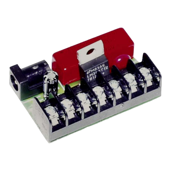
Loop Detector Board with On Board
provides a loop activated contact
n
n
Installation Diagram
2
3
4
5
6
7
N.O. Dry
Contacts
- or -
12V DC
+
Output
-
Schematic Diagram
+12V DC
COM
2
3
4
5
6
7
.
8
8
6
1
.
8
8
6
1
P
r
a
c
P
r
a
c
2
1
C
2
1
C
F
O
R
T
H
E
S
T
F
O
R
T
H
E
S
T
12 Volt Regulator
A
p
p
l
A
p
p
l
• Provide relay closure on off-hook
• Trigger a security camera
• Trigger a tape recorder
• Phone "In Use" indicator
S
p
e
c
S
p
e
c
(2) #4 screws (not included) or foam tape (included)
* Note: If driving an inductive load a protection device must be
placed across terminals 6 and 7.
h
t
t
h
t
t
Printed in the U.S.A.
t
i
c
e
Loop Detect Board
t
i
c
e
E
N
T
U
R
Y
E
N
T
U
R
Y
i
c
a
t
i
o
n
s
i
c
a
t
i
o
n
s
i
f
i
c
a
t
i
o
n
s
i
f
i
c
a
t
i
o
n
s
47.6mm x 30.5mm (1.875" x 1.2")
.45 kg (1 lb)
40 ohms
125 mA
18 mA
-26° to 54°C (-15° to 130° F)
35 VDC
500 mA with PS-2
63 dB minimum
200 VDC
500 mA
10 W Resistive*
7 pin screw terminal block
p
:
/
/
w
w
w
.
v
i
k
i
n
g
e
l
p
:
/
/
w
w
w
.
v
i
k
i
n
g
e
l
March 9, 2012
e
c
t
r
o
n
i
c
s
.
c
o
m
e
c
t
r
o
n
i
c
s
.
c
o
m
Advertisement
Table of Contents

Related Manuals for Viking LDB-1


Summary of Contents for Viking LDB-1
- Page 1 6 and 7. Due to the dynamic nature of the product design, the information contained in this document is subject to change without notice. Viking Electronics, and its affiliates and/or subsidiaries assume no responsibility for errors and omissions contained in this information. Revisions of this document or new editions of it may be issued to incorporate such changes.
-
Page 2: Limited Warranty
RA number on carton: In large printing, write the R.A. number on the outside of each carton being returned. Customer must contact Viking’s Technical Support at 715-386-8666 to determine possible causes for the problem. The customer MUST be able to step through recommended tests for diagnosis.
Need help?
Do you have a question about the LDB-1 and is the answer not in the manual?
Questions and answers