Table of Contents
Advertisement
GA-945PL-S3
Intel
Core
2 Extreme / Core
®
TM
Intel
Pentium
®
®
User's Manual
Rev. 1001
12ME-945PLS3-1001R
* The WEEE marking on the product indicates this product must not be disposed of with user's other household waste
and must be handed over to a designated collection point for the recycling of waste electrical and electronic equipment!!
* The WEEE marking applies only in European Union's member states.
TM
D / Pentium
4 LGA775 Processor Motherboard
®
2 Duo
Advertisement
Table of Contents

Related Manuals for Gigabyte GA-945PL-S3


Summary of Contents for Gigabyte GA-945PL-S3
- Page 1 GA-945PL-S3 Intel Core 2 Extreme / Core 2 Duo ® Intel Pentium D / Pentium 4 LGA775 Processor Motherboard ® ® ® User's Manual Rev. 1001 12ME-945PLS3-1001R * The WEEE marking on the product indicates this product must not be disposed of with user's other household waste and must be handed over to a designated collection point for the recycling of waste electrical and electronic equipment!! * The WEEE marking applies only in European Union's member states.
- Page 3 Copyright © 2006 GIGA-BYTE TECHNOLOGY CO., LTD. All rights reserved. The trademarks mentioned in the manual are legally registered to their respective companies. Notice The written content provided with this product is the property of Gigabyte. No part of this manual may be reproduced, copied, translated, or transmitted in any form or by any means without Gigabyte's prior written permission.
-
Page 4: Table Of Contents
Table of Contents Item Checklist ......................... 6 Optional Accessories ...................... 6 GA-945PL-S3 Motherboard Layout ................7 Block Diagram ........................ 8 Chapter 1 Hardware Installation ..................9 Considerations Prior to Installation ..............9 Feature Summary ..................10 Installation of the CPU and CPU Cooler ............12 1-3-1 Installation of the CPU .................. - Page 5 Chapter 3 Install Drivers ..................... 49 Install Chipset Drivers ..................49 Software Applications ..................50 Driver CD Information ..................50 Hardware Information ..................51 Contact Us ..................... 51 Chapter 4 Appendix ....................53 Unique Software Utilities ................53 4-1-1 EasyTune 5 Introduction ..................53 4-1-2 Xpress Recovery2 Introduction .................
-
Page 6: Item Checklist
Item Checklist IDE Cable x 1, FDD Cable x 1 SATA 3Gb/s Cable x 2 I/O Shield * The items listed above are for reference only, and are subject to change without notice. Optional Accessories 2 Ports USB2.0 Cable (Part Number: 12CR1-1UB030-51/R) 5.1/7.1 Surround Cable (Part Number: 12CF1-1AU004-01R ) - 6 -... -
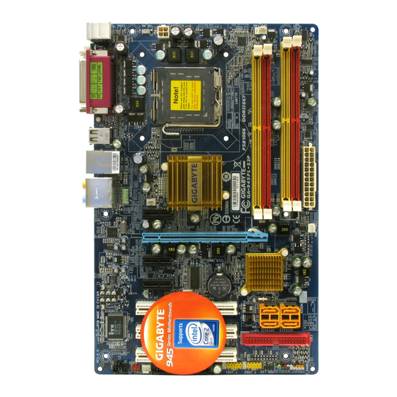
Page 7: Ga-945Pl-S3 Motherboard Layout
GA-945PL-S3 Motherboard Layout CPU_FAN ATX_12V KB_MS LGA775 USB_LAN Intel 945PL ® AUDIO F_AUDIO HDA_SUR PCIE_3 PCIE_16 8111B CLR_CMOS PCIE_1 Intel ICH7 ® PCIE_2 CODEC PCI1 SATAII0 SATAII2 BIOS SATAII3 PCI2 SATAII1 IDE1 PCI3 F_PANEL F_USB2 CD_IN SYS _FAN F_USB1 PWR_LED... -
Page 8: Block Diagram
Block Diagram CPUCLK+/-(200/133MHz) LGA775 PCIe CLK Processor (100MHz) Host Interface PCI Express x16 DDRII 400/533MHz DIMM Intel ® Dual Channel Memory 945PL RJ45 MCHCLK(200/133MHz) 8111B PCI Express Bus BIOS 4 SATA 3Gb/s Intel ® ATA33/66/100 PCIe CLK ICH7 IDE1 Channel (100MHz) Floppy 3 PCI Express x1... -
Page 9: Chapter 1 Hardware Installation
Chapter 1 Hardware Installation Considerations Prior to Installation Preparing Your Computer The motherboard contains numerous delicate electronic circuits and components which can become damaged as a result of electrostatic discharge (ESD). Thus, prior to installation, please follow the instructions below: 1. -
Page 10: Feature Summary
1 front panel connector 1 front audio connector 1 CD In connector 1 power LED connector 2 USB 2.0/1.1 connectors for additional 4 USB 2.0/1.1 ports by cables 1 SPDIF In/Out connector 1 HDA_SUR connector GA-945PL-S3 Motherboard - 10 -... - Page 11 Rear Panel I/O 1 PS/2 keyboard port 1 PS/2 mouse port 1 parallel port 1 serial port (COMA) 4 USB 2.0/1.1 port 1 RJ-45 ports 3 audio jacks (Line In / Line Out / MIC In) I/O Control IT8718 chip Hardware Monitor System voltage detection CPU temperature detection...
-
Page 12: Installation Of The Cpu And Cpu Cooler
CPU into position. (Grasping the CPU firmly between your thumb and forefinger, care- fully place it into the socket in a straight and down- wards motion. Avoid twisting or bending motions that might cause damage to the CPU during installation.) GA-945PL-S3 Motherboard - 12 -... -
Page 13: Installation Of The Cpu Cooler
1-3-2 Installation of the Cooler Male Push Pin The top of Female Push Pin Female Push Pin Fig.1 Fig. 2 Please apply an even layer of CPU cooler paste (Turning the push pin along the direction of arrow is to on the surface of the installed CPU. -
Page 14: Installation Of Memory
DIMM socket. Then push it down. Fig.2 Close the plastic clip at both edges of the DIMM sockets to lock the DIMM module. Reverse the installation steps when you wish to remove the DIMM module. GA-945PL-S3 Motherboard - 14 -... - Page 15 Dual Channel Memory Configuration GA-945PL-S3 supports the Dual Channel Technology. After operating the Dual Channel Technology, the bandwidth of Memory Bus will add double. GA-945PL-S3 includes 4 DIMM sockets, and each Channel has two DIMM sockets as following: Channel 0 : DDRII1, DDRII2...
-
Page 16: Installation Of Expansion Cards
PCI Express x16 slot. When you try uninstall the VGA card, please gently press the latch as the picture to the left shows to release the card. GA-945PL-S3 Motherboard - 16 -... -
Page 17: I/O Back Panel Introduction
I/O Back Panel Introduction PS/2 Keyboard and PS/2 Mouse Connector To install a PS/2 port keyboard and mouse, plug the mouse to the upper port (green) and the keyboard to the lower port (purple). LPT (Parallel Port) The parallel port allows connection of a printer, scanner and other peripheral devices. COMA (Serial Port) Devices like mouses, modems, and etc. -
Page 18: Connectors Introduction
Connectors Introduction ATX_12V F_PANEL ATX (Power Connector) CD_IN CPU_FAN SPDIF_IO SYS_FAN HDA_SUR IDE1 F_USB1 / F_USB2 SATAII0 / 1 / 2 / 3 CLR_CMOS PWR_LED F_AUDIO GA-945PL-S3 Motherboard - 18 -... - Page 19 1/2) ATX_12V/ATX (Power Connector) With the use of the power connector, the power supply can supply enough stable power to all the components on the motherboard. Before connecting the power connector, please make sure that all components and devices are properly installed. Align the power connector with its proper location on the motherboard and connect tightly.
- Page 20 Slave (for information on settings, please refer to the instructions located on the IDE device). Before attaching the IDE cable, please take note of the foolproof groove in the IDE connector. GA-945PL-S3 Motherboard - 20 -...
- Page 21 6) FDD (FDD Connector) The FDD connector is used to connect the FDD cable while the other end of the cable connects to the FDD drive. The types of FDD drives supported are: 360KB, 720KB, 1.2MB, 1.44MB and 2.88MB. Before attaching the FDD cable, please take note of the foolproof groove in the FDD connector.
-
Page 22: Front Audio Connector
FSENSE2 By default, the audio driver is configured to support HD Audio. To connect an AC97 front panel audio module to this connector, please refer to the instructions on Page 70 about the software settings. GA-945PL-S3 Motherboard - 22 -... - Page 23 10) F_PANEL (Front Panel Jumper) Please connect the power LED, PC speaker, reset switch and power switch etc of your chassis front panel to the F_PANEL connector according to the pin assignment below. Speaker Connector Message LED/ Power Power/ Switch Sleep LED Reset Switch IDE Hard Disk Active LED...
- Page 24 SPDIF cable, incorrect connection between the cable and connector will make the device unable to work or even damage it. For optional SPDIF cable, please contact your local dealer. Pin No. Definition Power No Pin SPDIF SPDIFI GA-945PL-S3 Motherboard - 24 -...
- Page 25 13) HDA_SUR (Surround Center Connector) Attach the connector of the 5.1/7.1 Surround Cable (optional) to this connector. Pin No. Definition LEF_P SURR_RR CEN_P SURR_LL CEN_JD SURR_JD -SUR_DET No Pin S_SURR_JD S_SURR_LL S_SURR_RR 14) F_USB1 / F_USB2 (Front USB Connectors) Be careful with the polarity of the front USB connector. Check the pin assignment carefully while you connect the front USB cable, incorrect connection between the cable and connector will make the device unable to work or even damage it.
- Page 26 You may clear the CMOS data to its default values by this header. To clear CMOS, temporarily short the two pins. Default doesn't include the jumper to avoid improper use of this header. Open: Normal Short: Clear CMOS GA-945PL-S3 Motherboard - 26 -...
- Page 27 17) BAT Danger of explosion if battery is incorrectly replaced. Replace only with the same or equivalent type recommended by the manufacturer. Dispose of used batteries according to the manufacturer's instructions. If you want to erase CMOS... 1. Turn off the computer and unplug the power cord. 2.
- Page 28 GA-945PL-S3 Motherboard - 28 -...
-
Page 29: Chapter 2 Bios Setup
Chapter 2 BIOS Setup BIOS (Basic Input and Output System) includes a CMOS SETUP utility which allows user to configure required settings or to activate certain system features. The CMOS SETUP saves the configuration in the CMOS SRAM of the motherboard. When the power is turned off, the battery on the motherboard supplies the necessary power to the CMOS SRAM. -
Page 30: The Main Menu (For Example: Bios Ver. : E6)
If you can't find the setting you want, please press "Ctrl+F1" to search the advanced option hidden. Please Load Optimized Defaults in the BIOS when somehow the system works not stable as usual. This action makes the system reset to the default for stability. GA-945PL-S3 Motherboard - 30 -... - Page 31 Standard CMOS Features This setup page includes all the items in standard compatible BIOS. Advanced BIOS Features This setup page includes all the items of Award special enhanced features. Integrated Peripherals This setup page includes all onboard peripherals. Power Management Setup This setup page includes all the items of Green function features.
-
Page 32: Standard Cmos Features
Select this if no IDE/SATA devices are used and the system will skip the automatic detection step and allow for faster system start up. Access Mode Use this to set the access mode for the hard drive. The two options are: Large/Auto(default: Auto) GA-945PL-S3 Motherboard - 32 -... - Page 33 Capacity Capacity of currently installed hard disk. Cylinder Number of cylinders Head Number of heads Precomp Write precomp Landing Zone Landing zone Sector Number of sectors Drive A The category identifies the types of floppy disk drive A that has been installed in the computer. None No floppy drive installed 360K, 5.25"...
-
Page 34: Advanced Bios Features
If you want to cancel the setting of password, please just press ENTER to make [SETUP] empty. (Note) This item will show up when you install a processor which supports this function. GA-945PL-S3 Motherboard - 34 -... - Page 35 CPU Hyper-Threading (Note) Enabled Enable CPU Hyper Threading Feature. Please note that this feature is only working for operating system with multi processors mode supported. (Default value) Disabled Disables CPU Hyper Threading. Limit CPUID Max. to 3 (Note) Enabled Limit CPUID Maximum value to 3 when use older OS like NT4. Disabled Disable CPUID Limit for windows XP.
-
Page 36: Integrated Peripherals
SATA Port 1/3 Set to This value will auto make by the setting "On-Chip SATA Mode" and "PATA IDE Set to". If PATA IDE were set to Ch. 0 Master/Slave,this function will auto set to Ch. 1 Master/Slave. GA-945PL-S3 Motherboard - 36 -... - Page 37 USB Controller Enabled Enable USB Controller. (Default value) Disabled Disable USB Controller. USB 2.0 Controller Disable this function if you are not using onboard USB 2.0 feature. Enabled Enable USB 2.0 Controller. (Default value) Disabled Disable USB 2.0 Controller. USB Keyboard Support Enabled Enable USB Keyboard Support.
-
Page 38: Power Management Setup
This feature requires an ATX power supply that provides at least 1A on the 5VSB lead. Disabled Disable this function. Enabled Enable PME Event Wake up. (Default value) Power On by Ring Disabled Disable Power on by Ring function. Enabled Enable Power on by Ring function. (Default value) GA-945PL-S3 Motherboard - 38 -... - Page 39 Resume by Alarm You can set "Resume by Alarm" item to enabled and key in Date/time to power on system. Disabled Disable this function. (Default value) Enabled Enable alarm function to POWER ON system. If Resume by Alarm is Enabled. Date (of Month) Alarm : Everyday, 1~31 Time (hh: mm: ss) Alarm : (0~23) : (0~59) : (0~59)
-
Page 40: Pnp/Pci Configurations
Auto assign IRQ to PCI 2. (Default value) 3,4,5,7,9,10,11,12,14,15 Set IRQ 3,4,5,7,9,10,11,12,14,15 to PCI 2. PCI 3 IRQ Assignment Auto Auto assign IRQ to PCI 3. (Default value) 3,4,5,7,9,10,11,12,14,15 Set IRQ 3,4,5,7,9,10,11,12,14,15 to PCI 3. GA-945PL-S3 Motherboard - 40 -... -
Page 41: Pc Health Status
PC Health Status CMOS Setup Utility-Copyright (C) 1984-2006 Award Software PC Health Status Reset Case Open Status [Disabled] Item Help Case Opened Menu Level Vcore DDR18V +3.3V +12V Current CPU Temperature Current CPU FAN Speed 3375 RPM Current SYSTEM FAN Speed CPU Warning Temperature [Disabled] CPU FAN Fail Warning... - Page 42 Note: In fact, the Voltage option can be used for CPU fans with 3-pin or 4-pin power cables. However, some 4-pin CPU fan power cables are not designed following Intel 4-Wire fans PWM control specifications. With such CPU fans, selecting PWM will not effectively reduce the fan speed. GA-945PL-S3 Motherboard - 42 -...
-
Page 43: Mb Intelligent Tweaker(M.i.t.)
MB Intelligent Tweaker(M.I.T.) CMOS Setup Utility-Copyright (C) 1984-2006 Award Software MB Intelligent Tweaker(M.I.T.) CPU Clock Ratio (Note) [18X] Item Help Robust Graphics Booster [Auto] Menu Level C.I.A. 2 [Disabled] CPU Host Clock Control [Disabled] x CPU Host Frequency (Mhz) x PCI Experss Frequency (Mhz) Auto System Memory Multiplier [Auto]... - Page 44 Set DIMM OverVoltage Control to +0.3V. +0.4V Set DIMM OverVoltage Control to +0.4V. +0.5V Set DIMM OverVoltage Control to +0.5V. +0.6V Set DIMM OverVoltage Control to +0.6V. Incorrect using it may cause your system broken. For power End-User use only! GA-945PL-S3 Motherboard - 44 -...
- Page 45 PCI-E OverVoltage Control Normal Set PCI-E OverVoltrage Control to Normal. (Default value) +0.1V Set PCI-E OverVoltrage Control to +0.1V. +0.2V Set PCI-E OverVoltrage Control to +0.2V. +0.3V Set PCI-E OverVoltrage Control to +0.3V. Incorrect using it may cause your system broken. For power End-User use only! FSB OverVoltage Control Normal Set FSB OverVoltage Control to Normal.
-
Page 46: Load Fail-Safe Defaults
MB Intelligent Tweaker(M.I.T.) ESC: Quit : Select Item F8: Q-Flash F10: Save & Exit Setup Load Optimized Defaults Selecting this field loads the factory defaults for BIOS and Chipset Features which the system automatically detects. GA-945PL-S3 Motherboard - 46 -... -
Page 47: Set Supervisor/User Password
2-10 Set Supervisor/User Password CMOS Setup Utility-Copyright (C) 1984-2006 Award Software Standard CMOS Features Load Fail-Safe Defaults Advanced BIOS Features Load Optimized Defaults Integrated Peripherals Set Supervisor Password Power Management Setup Set User Password PnP/PCI Configurations Save & Exit Setup Enter Password: PC Health Status Exit Without Saving... -
Page 48: Save & Exit Setup
MB Intelligent Tweaker(M.I.T.) ESC: Quit : Select Item F8: Q-Flash F10: Save & Exit Setup Abandon all Data Type "Y" will quit the Setup Utility without saving to RTC CMOS. Type "N" will return to Setup Utility. GA-945PL-S3 Motherboard - 48 -... -
Page 49: Chapter 3 Install Drivers
Chapter 3 Install Drivers Pictures below are shown in Windows XP. Insert the driver CD-title that came with your motherboard into your CD-ROM drive, the driver CD-title will auto start and show the installation guide. If not, please double click the CD-ROM device icon in "My computer", and execute the Run.exe. -
Page 50: Software Applications
This page displays all the tools that Gigabyte developed and some free software, you can choose anyone you want and press "install" to install them. Driver CD Information This page lists the contents of software and drivers in this CD-title. GA-945PL-S3 Motherboard - 50 -... -
Page 51: Hardware Information
Hardware Information This page lists all device you have for this motherboard. Contact Us Please see the last page for details. - 51 - Install Drivers... - Page 52 GA-945PL-S3 Motherboard - 52 -...
-
Page 53: Chapter 4 Appendix
Chapter 4 Appendix Unique Software Utilities (Not all model support these Unique Software Utilities, please check your MB features.) 4-1-1 EasyTune 5 Introduction EasyTune 5 presents the most convenient Windows based system performance enhancement and manageability utility. Featuring several powerful yet easy to use tools such as 1) Overclocking for enhancing system performance, 2) C.I.A. -
Page 54: Xpress Recovery2 Introduction
2. System storage capacity and the reading/writing speed of the hard disk will affect the data backup speed. 3. It is recommended that Xpress Recovery2 be immediately installed once you com- plete installations of OS and all required drivers as well as software. GA-945PL-S3 Motherboard - 54 -... - Page 55 The Main Screen of Xpress Recovery2 1. RESTORE: Restore the backed-up data to your hard disk. (This button will not appear if there is no backup file.) 2. BACKUP: Back up data from hard disk. 3. REMOVE: Remove previously-created backup files to release disk space.
-
Page 56: Flash Bios Method Introduction
Please note that because updating BIOS has potential risk, please do it with caution!! We are sorry that Gigabyte Technology Co., Ltd is not responsible for damages of system because of incorrect manipulation of updating BIOS to avoid any claims from end-users. - Page 57 Entering the Q-Flash utility: Step1: To use Q-Flash utility, you must press Del in the boot screen to enter BIOS menu. CMOS Setup Utility-Copyright (C) 1984-2004 Award Software Standard CMOS Features Select Language Advanced BIOS Features Load Fail-Safe Defaults Integrated Peripherals Load Optimized Defaults Power Management Setup Set Supervisor Password...
- Page 58 Save Main BIOS to Floppy Save Backup BIOS to Floppy Enter : Run :Move ESC:Reset F10:Power Off After BIOS file is read, you'll see a confirmation dialog box asking you "Are you sure to update BIOS?" GA-945PL-S3 Motherboard - 58 -...
- Page 59 3. Press Y button on your keyboard after you are sure to update BIOS. Then it will begin to update BIOS. The progress of updating BIOS will be displayed. Please do not take out the floppy disk when it begins flashing BIOS. 4.
-
Page 60: Updating Bios With Q-Flash Utility On Single-Bios Motherboards
PnP/PCI Configurations Set User Password PC Health Status Save & Exit Setup MB Intelligent Tweaker(M.I.T.) Exit Without Saving ESC: Quit F3: Change Language F8: Q-Flash F10: Save & Exit Setup Time, Date, Hard Disk Type... GA-945PL-S3 Motherboard - 60 -... - Page 61 Exploring the Q-Flash utility screen The Q-FlashBIOS utility screen consists of the following key components. Q-Flash utility bar Q-Flash Utility V1.30 Flash Type/Size.........SST 49LF003A 256K Keep DMI Data Enable Task menu for Update BIOS from Floppy Q-Flash utility Save BIOS to Floppy Action bar Enter : Run :Move...
- Page 62 Press Del to enter BIOS menu after system reboots and "Load BIOS Fail-Safe Defaults". See how to Load BIOS Fail-Safe Defaults, please kindly refer to Step 6 to 7 in Part One. Congratulation!! You have updated BIOS successfully!! GA-945PL-S3 Motherboard - 62 -...
- Page 63 Method 2 : @BIOS Utility If you do not have a DOS startup disk, we recommend that you use the new @BIOS utility. @BIOS allows users to update their BIOS under Windows. Just select the desired @BIOS server to download the latest version of BIOS.
- Page 64 Gigabyte's web site for downloading and updating it according to method II. IV. Please note that any interruption during updating will cause system unbooted. V. Do not use @BIOS and C.O.M. (Corporate Online Management) at the same time. GA-945PL-S3 Motherboard - 64 -...
-
Page 65: 4- / 6- / 8- Channel Audio Introduction
4-1-4 2- / 4- / 6- / 8- Channel Audio Introduction This motherboard comes with three audio jacks. To set up multi- channel surround sound, install an additional 5.1/7.1 surround cable (optional) and enable the feature through the audio driver. Installing the 5.1/7.1 Surround Cable (Optional) The 5.1/7.1 Surround Cable provides center/ subwoofer speaker out, rear speaker out, and side... - Page 66 Out jack, a small window will pop up and ask you what type of equipment is connected. Choose Headphone or Line Out depending on the device connected and click OK. The 2-channel audio setup is completed. GA-945PL-S3 Motherboard - 66 -...
- Page 67 Setting Up 4-Channel Audio STEP 1 : After installation of the audio driver, you should find an Audio Manager icon in your system tray (you can also find the icon in Control Panel). Double- click the icon to open the Audio Control Panel. STEP 2: In the Audio Control Panel, click the Audio I/O tab.
- Page 68 Choose a device depend- ing on the type of speaker connected (6-channel audio consists of Front Speaker Out (Line Out), Rear Speaker Out, and Center/Subwoofer Speaker Out) then click OK. The 6-channel audio setup is completed. GA-945PL-S3 Motherboard - 68 -...
- Page 69 Setting Up 8-Channel Audio STEP 1 : After installation of the audio driver, you should find an Audio Manager icon in your system tray (you can also find the icon in Control Panel). Double- click the icon to open the Audio Control Panel. STEP 2: In the Audio Control Panel, click the Audio I/O tab.
- Page 70 AC97 Audio mode, go to the Audio Control Panel and click the Audio I/O tab. In the ANA- LOG area, click the Tool icon and then select the Disable front panel jack detection check box. This action completes the AC'97 Audio configuration. GA-945PL-S3 Motherboard - 70 -...
-
Page 71: Troubleshooting
Troubleshooting Below is a collection of general asked questions. To check general asked questions based on a specific motherboard model, please log on to http://www.gigabyte.com.tw Question 1: I cannot see some options that were included in previous BIOS after updating BIOS. Why? Answer: Some advanced options are hidden in new BIOS version. - Page 72 GA-945PL-S3 Motherboard - 72 -...
- Page 73 - 73 - Appendix...
- Page 74 GA-945PL-S3 Motherboard - 74 -...
- Page 75 - 75 - Appendix...
- Page 76 GA-945PL-S3 Motherboard - 76 -...
- Page 77 - 77 - Appendix...
- Page 78 GA-945PL-S3 Motherboard - 78 -...
- Page 79 Shenyang Tech. Support: TEL: +86-24-83992901 http://rma.gigabyte-usa.com FAX: +86-24-83992909 Web address: http://www.gigabyte-latam.com India Japan GIGABYTE TECHNOLOGY (INDIA) LIMITED NIPPON GIGA-BYTE CORPORATION WEB address : http://www.gigabyte.in WEB address : http://www.gigabyte.co.jp Australia Singapore GIGABYTE TECHNOLOGY PTY. LTD. GIGA-BYTE SINGAPORE PTE. LTD. WEB address : http://www.gigabyte.com.au WEB address : http://www.gigabyte.com.sg...
- Page 80 WEB address : http://www.gigabyte.com.lv GIGA-BYTE TECHNOLOGY B.V. Poland WEB address : http://www.giga-byte.nl Office of GIGA-BYTE TECHNOLOGY Co., Ltd. in POLAND France WEB address : http://www.gigabyte.pl GIGABYTE TECHNOLOGY FRANCE Ukraine WEB address : http://www.gigabyte.fr WEB address : http://www.gigabyte.kiev.ua Italy Romania WEB address : http://www.giga-byte.it Representative Office Of GIGA-BYTE Technology Co., Ltd.
Need help?
Do you have a question about the GA-945PL-S3 and is the answer not in the manual?
Questions and answers