Table of Contents
Advertisement
M The author assumes no responsibility for any
errors or omissions that may appear in this
document nor does the author make a
commitment to update the information
contained herein.
M Third-party brands and names are the
property of their respective owners.
M Please do not remove any labels on
motherboard, this may void the warranty of
this motherboard.
M Due to rapid change in technology, some of
the specifications might be out of date
beforepublication of this booklet.
Advertisement
Table of Contents

Related Manuals for Gigabyte GA-8SIMLH SERIES


Summary of Contents for Gigabyte GA-8SIMLH SERIES
- Page 1 M The author assumes no responsibility for any errors or omissions that may appear in this document nor does the author make a commitment to update the information contained herein. M Third-party brands and names are the property of their respective owners. M Please do not remove any labels on motherboard, this may void the warranty of this motherboard.
-
Page 3: Declaration Of Conformity
Declaration of Conformity We, Manufacturer/Importer (full address) G.B.T. Technology Träding GMbH Ausschlager Weg 41, 1F, 20537 Hamburg, Germany declare that the product ( description of the apparatus, system, installation to which it refers) Mother Board GA-8SIMLH is in conformity with (reference to the specification under which conformity is declared) in accordance with 89/336 EEC-EMC Directive o EN 55011... - Page 4 DECLARATION OF CONFORMITY Per FCC Part 2 Section 2.1077(a) Responsible Party Name: G.B.T. INC. (U.S.A.) Address: 17358 Railroad Street City of Industry, CA 91748 Phone/Fax No: (818) 854-9338/ (818) 854-9339 hereby declares that the product Product Name: Motherboard Model Number: GA-8SIMLH Conforms to the following specifications: FCC Part 15, Subpart B, Section 15.107(a) and Section 15.109(a),...
- Page 5 GA-8SIMLH-P(-C) P4 Titan Series Motherboard USER'S MANUAL Pentium 4 Processor Motherboard ® Rev. 3201 12ME-8SIMLHP-3201...
-
Page 6: Table Of Contents
Table of Content Item Checklist ..................4 Chapter 1 Introduction .................5 Features Summary ..................5 GA-8SIMLH-P(-C) Motherboard Layout ........... 7 Block Diagram .................... 8 Chapter 2 Hardware Installation Process ..........10 Step 1: Install the Central Processing Unit (CPU) ........11 Step 1-1: CPU Installation ................... 11 Step 1-2 : CPU Cooling Fan Installation .............. - Page 7 PnP/PCI Configurations ................45 PC Health Status ..................46 Frequency/Voltage Control ..............48 Top Performance ..................50 Load Fail-Safe Defaults ................51 Load Optimized Defaults ................. 52 Set Supervisor/User Password ............... 53 Save & Exit Setup ..................54 Exit Without Saving ................. 55 Chapter 4 Technical Reference ............
-
Page 8: Item Checklist
Item Checklist þ The GA-8SIMLH-P or GA-8SIMLH-P-C motherboard o 2 Port USB Cable x 1 þ IDE cable x 1/ Floppy cable x 1 o 4 Port USB Cable x 1 þ CD for motherboard driver & utility o SPDIF-KIT x 1 (SPDIF Out KIT) þ... -
Page 9: Chapter 1 Introduction
Chapter 1 Introduction Features Summary Form Factor — 24.4cm x 21.5cm Micro ATX size form factor, 4 layers PCB. — Socket 478 for Intel Micro FC-PGA2 Pentium 4 processor ® ® — Support Intel Pentium 4 (Northwood, 0.13 m) processor ®... - Page 10 Hardware Monitor — CPU/System Fan Revolution detect — CPU/System Fan Control — CPU Overheat Warning — System Voltage Detect On-Board Sound — Realtek ALC650 CODEC — Line Out / 2 front speaker — Line In / 2 rear speaker(by s/w switch) —...
-
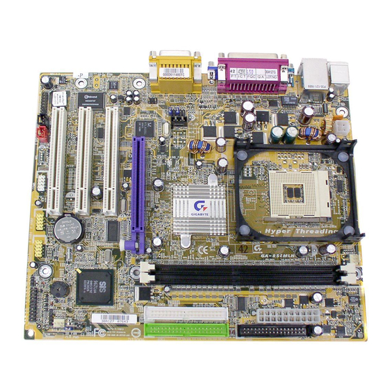
Page 11: Ga-8Simlh-P(-C) Motherboard Layout
GA-8SIMLH-P(-C) Motherboard Layout DIMM _LED KB_MS ATX_12V USB_LAN* SOC KET478 CD_IN SiS 651 SUR_CEN RTL8101L* PCI1 CODEC SiS 962L PCI2 CLR_ PWD PCI3 SYS _FAN BIOS F_U SB2 PWR_LED SPDIF_I MODEM* COMB F_U SB1 F_PANEL SPDIF "*" For GA-8SIMLH-P only . - 7 - Introduction... -
Page 12: Block Diagram
Block Diagram Pentium 4 CPUCLK+/- (100/133MHz) Socket 478 AGP 2X/4X VGA Port System Bus AGPCLK 400/533MHz (66MHz) 200/266/333MHz SiS 651 ZCLK (66MHz) HCLK+/- (100/133MHz) RJ45* 66 MHz 3 PCI 33 MHz 14.318 MHz 48 MHz RTL8101L* BIOS SiS 962L Game Port AC97 Link Floppy LPC BUS... - Page 13 - 9 - Introduction...
-
Page 14: Chapter 2 Hardware Installation Process
Chapter 2 Hardware Installation Process To set up your computer, you must complete the following steps: Step 1- Install the Central Processing Unit (CPU) Step 2- Install memory modules Step 3- Install expansion cards Step 4- Connect ribbon cables, cabinet wires, and power supply Step 2 Step 1 Step 4... -
Page 15: Step 1: Install The Central Processing Unit (Cpu)
Step 1: Install the Central Processing Unit (CPU) Before installing the processor, adhere to the following warning: If you do not match the CPU socket Pin 1 and CPU cut edge well, it will cause improper installation. Please change the insert orientation. Please make sure the CPU type is supported by the motherboard. -
Page 16: Step 1-2 : Cpu Cooling Fan Installation
Step 1-2 : CPU Cooling Fan Installation Before installing the CPU cool fan , adhere to the following warning: 1.Please use Intel approved cooling fan. 2.We recommend you to apply the thermal tape to provide better heat conduction between your CPU and cooling fan. (The CPU cooling fan might stick to the CPU due to the hardening of the thermal paste. -
Page 17: Step 2: Install Memory Modules
Step 2: Install memory modules Before installing the processor and heatsink, adhere to the following warning: When DIMM_LED is ON, do not install/remove DIMM from socket. Please note that the DIMM module can only fit in one direction due to the one notches. Wrong orientation will cause improper installation. - Page 18 1. The DIMM slot has a notch, so the DIMM memory module can only fit in one direction. 2. Insert the DIMM memory module vertically into the DIMM slot. Then push it down. 3. Close the plastic clip at both edges of the DIMM slots to lock the DIMM module.
-
Page 19: Step 3: Install Expansion Cards
Step 3: Install expansion cards 1. Read the related expansion card’ s instruction document before install the expansion card into the computer. 2. Remove your computer's chassis cover, necessary screws and slot bracket from the computer. 3. Press the expansion card firmly into expansion slot in motherboard. 4. -
Page 20: Step 4: Connect Ribbon Cables, Cabinet Wires, And Power Supply
Step 4: Connect ribbon cables, cabinet wires, and power supply Step 4-1: I/O Back Panel Introduction u PS/2 Keyboard and PS/2 Mouse Connector Ø This connector supports standard PS/2 PS/2 Mouse Connector keyboard and PS/2 mouse. (6 pin Female) PS/2 Keyboard Connector (6 pin Female) v USB &... -
Page 21: Audio Connectors
w Parallel Port , Serial Port and VGA Port (LPT/COMA/VGA) Parallel Port (25 pin Female) Ø This connector supports 1 standard COM port, 1 Parallel port and 1 VGA port. Device like printer can be connected to Parallel port; mouse and modem etc can be connected to Serial ports. -
Page 22: Step 4-2: Connectors & Jumper Setting Introduction
Step 4-2: Connectors & Jumper Setting Introduction 1) ATX_12V 12) SUR_CEN 2) ATX 13) CD_IN 3) CPU_FAN 14) SPDIF 4) SYS_FAN 15) SPDIF_I 5) IDE1/IDE2 16) IR 6) FDD 17) F_USB1/F_USB2 7) DIMM_LED 18) COMB 8) PWR_LED 19) CI 9) F_PANEL 20) MODEM * 10) BAT 21) CLR_PWD... - Page 23 1) ATX_12V ( +12V Power Connector) This connector (ATX _12V) suppliesthe CPU operation voltage (Vcore). If this " ATX_ 12V connector" is not connected, system cannot boot. Pin No. Definition +12V +12V 2) ATX (ATX Power) AC power cord should only be connected to your power supply unit after ATX power cable and other related devices are firmly connected to the mainboard.
- Page 24 3) CPU_FAN (CPU FAN Connector) Please note, a proper installation of the CPU cooler is essential to prevent the CPU from running under abnormal condition or damaged by overheating.The CPU fan connector supports Max. current up to 600 mA. Pin No. Definition +12V Sense...
- Page 25 5) IDE1/ IDE2(IDE1/IDE2 Connector) Please connect first harddisk to IDE1 and connect CDROM to IDE2. The red stripe of the ribbon cable must be the same side with the Pin1. 6) FDD (Floppy Connector) Please connect the floppy drive ribbon cables to FDD. It supports 360K,720K,1.2M,1.44M and 2.88Mbytes floppy disk types.
- Page 26 7) DIMM_LED Do not remove memory modules while DIMM LED is on. It might cause short or other unexpected damages due to the 2.5V/3.3V stand by voltage. Remove memory modules only when AC Power cord is disconnected. 8) PWR_LED PWR_LED is connect with the system power indicator to indicate whether the system is on/off. It will blink when the system enters suspend mode.
- Page 27 9) F_PANEL (2x10 pins connector) Please connect the power LED, PC peaker, reset switch and power switch etc of your chassis front panel to the F_PANEL connector according to the pin assignment above. Soft Po wer Speaker Connector Me ssa g e LED /Po w e r / Connector Sleep LED PW -...
- Page 28 10) BAT (Battery) CAUTION v Danger of explosion if battery is incorrectly replaced. v Replace only with the same or equivalent type recommended by the manufacturer. v Dispose of used batteries according to the manufacturer's instructions. If you want to erase CM OS... 1.Turn OFF the computer and unplug the power cord.
- Page 29 12) SUR_CEN Please contact your nearest dealer for optional SUR_CEN cable. Pin No. Definition SUR OUTL SUR OUTR No Pin CENTER_OUT BASS_OUT 13) CD_IN (CD IN, Black) Connect CD-ROM or DVD-ROM audio out to the connector. Pin No. Definition CD-L CD_R - 25 - Hardware Installation Process...
- Page 30 14) SPDIF (SPDIF Out) The SPDIF output is capable of providing digital audio to external speakers or com pressed AC3 data to an external Dolby Digital Decoder. Use this feature only when your stereo system has digital input function. Pin No. Definition SPDIF Out 15) SPDIF_I (SPDIF In) Use this feature only when your device has digital output function.
- Page 31 16) IR Be careful with the polarity of the IR connector while you connect the IR. Please contact you nearest dealer for optional IR device. Pin No. Definition No Pin IR Data Input IR Data Output 17) F_ USB1 / F_USB2(Front USB Connector, Yellow ) Be careful with the polarity of the front USB connector.
- Page 32 18) COMB (COM B Connector)(White) Be careful with the polarity of the COMB connector. Check the pin assignment while you connect the COMB cable. Please contact your nearest dealer for optional COMB cable. Pin No. Definition NDCDB- NSINB NSOUTB NDTRB- NDSRB- NRTSB- NCTSB-...
- Page 33 20) MODEM * Please contact your nearest dealer for optional Modem card. Pin No. Definition VDD33 AC OUT AC BCK +12V AC DIN VAUX33 AC DOUT AC SYNC AC RSTB No Pin 21) CLR_PWD When Jum per is set to "open" and system is restarted, the password that is set will be cleared. On the contrary when Jumper is set to "close", the current status remains.
- Page 34 GA-8SIMLH-P(-C) Motherboard - 30 -...
-
Page 35: Chapter 3 Bios Setup
Chapter 3 BIOS Setup BIOS Setup is an overview of the BIOS Setup Program. The program that allows users to modify the basic system configuration. This type of information is stored in battery-backed CMOS RAM so that it retains the Setup information when the power is turned off. ENTERING SETUP Powering ON the comput e r and pressing <Del>... -
Page 36: The Main Menu (For Example: Bios Ver. : F9)
GETTING HELP Main Menu The on-line description of the highlighted setup function is displayed at the bottom of the screen. Status Page Setup Menu / Option Page Setup Menu Press F1 to pop up a small help window that describes the appropriate keys to use and the possible selections for the highlighted item. -
Page 37: Integrated Peripherals
Integrated Peripherals This setup page includes all onboard peripherals. Power Manag ement Setup This setup page includes all the items of Green function features. PnP/PCI Configurations This setup page includes all the configurations of PCI & PnP ISA resources. PC Health Status This setup page is the System auto detect Temperature, voltage, fan, speed. -
Page 38: Standard Cmos Features
Standard CMOS Features CMOS Setup Utility -Copy right (C) 1984-2003 Aw ard Softw are Standard CMOS Features Date (mm:dd:y y ) Fri, May 3 2002 Item Help Time (hh:mm:ss) 17:56:23 Menu Lev el u Change the day , month, }IDE Primary Master None y ear }IDE Primary Slav e... - Page 39 C Time The times format in <hour> <mi n ute> <second>. The time is calculated base on the 24-hour military- time clock. For example, 1 p.m. is 13:00:00. C IDE Pri mary Master, S lave / IDE Secondary Master, Slave The category identifies the types of hard disk from drive C to F that has been installed in the computer.
-
Page 40: Base Memory
C Floppy 3 Mode Support (for J apan Area) Normal Floppy Driv e. (Default v alue) 8Disabled 8Driv e A Driv e A is 3 mode Floppy Driv e. 8Driv e B Driv e B is 3 mode Floppy Driv e. Driv e A &... -
Page 41: Advanced Bios Features
Advanced BIOS Features CMOS Setup Utility -Copy right (C) 1984-2003 Aw ard Softw are Adv anced BIOS Features First Boot Dev ice [Floppy ] Item Help Second Boot Dev ice [HDD-0] Menu Lev el u Third Boot Dev ice [CDROM] Select Boot Dev ice Boot Up Floppy Seek [Disabled]... -
Page 42: Password Check
Select y our boot dev ice priority by LAN. 8LAN Select y our boot dev ice priority by Disabled. 8Disabled C Boot Up Fl oppy Seek During POST, BIOS will determine the floppy disk drive installed is 40 or 80 tracks. 360 K type is 40 tracks 720 K, 1.2 M and 1.44 M are all 80 tracks. -
Page 43: Integrated Peripherals
Integrated Peripherals CMOS Setup Utility -Copy right (C) 1984-2003 Aw ard Softw are Integrated Peripherals IDE1 Conductor Cable [Auto] Item Help Menu Lev el u IDE2 Conductor Cable [Auto] On-Chip Primary PCI IDE [Enabled] [Auto] On-Chip Secondary PCI IDE [Enabled] Auto-detect IDE AC97 Audio [Enabled]... -
Page 44: Ac97 Audio
C IDE2 Conductor Cable Will be automatically detected by BIOS. (Default Value) 8Auto Set IDE2 Conductor Cable to ATA66/100/133 (Please make sure y our IDE 8ATA66/100/133 dev ice and cable is compatible w ith ATA66/100/133). Set IDE2 Conductor Cable to ATA33 (Please make sure your IDE dev ice and 8ATA33 cable is compatible w ith ATA33). - Page 45 CInit Display First Set Init Display First to AGP. (Default v alue) 8AGP Set Init Display First to PCI. 8PCI C Onboard Modem Function * Disable this function. (Default Value) 8Disabled Enable Onboard Modem function. 8Enabled C Onboard Serial Port A BIOS w ill automatically setup the port A address.
-
Page 46: Onboard Parallel Port
C Onboard Parallel port Enable onboard LPT port and address is 378/IRQ7. (Default Value) 8378/IRQ7 Enable onboard LPT port and address is 278/IRQ5. 8278/IRQ5 Disable onboard LPT port. 8Disabled Enable onboard LPT port and address is 3BC/IRQ7. 83BC/IRQ7 CParallel Port Mode Using Parallel port as Standard Parallel Port. -
Page 47: Power Management Setup
Power Management Setup CMOS Setup Utility -Copy right (C) 1984-200 Aw ard Softw are Pow er Management Setup ACPI Suspend Ty pe [S1(POS)] Item Help Soft-Off by PWR_BTTN [Off] Menu Lev el u Sy stem After AC Back [Off] [S1] IRQ [3-7, 9-15], NMI [Enabled] Set suspend ty pe to... -
Page 48: Resume By Alarm
C IRQ [3-7, 9-15], NMI Disable this function. 8Disabled Enable this function. (Default v alue) 8Enabled C ModemRingOn Disable Modem Ring on function. 8Disabled Enable Modem Ring on function. (Default Value) 8Enabled C PME Event Wake Up Disable this function. 8Disabled Enable PME Ev ent Wake up. -
Page 49: Pnp/Pci Configurations
PnP/PCI Configurations CMOS Setup Utility -Copy right (C) 1984-2003 Aw ard Softw are PnP/PCI Configurations PCI 1 IRQ Assignment [Auto] Item Help PCI 2 IRQ Assignment [Auto] Menu Lev el u PCI 3 IRQ Assignment [Auto] higf: Mov e Enter:Select +/-/PU/PD:Value F10:Sav e ESC:Ex it F1:General Help F5:Prev ious Values F6:Fail-Safe Defaults... -
Page 50: Pc Health Status
PC Health Status CMOS Setup Utility -Copy right (C) 1984-2003 Aw ard Softw are PC Health Status Reset Case Open Status [Disabled] Item Help Case Opened Menu Lev el u VCORE 1.71V +3.3V 3.29V 4.99V +12V 11.73V Current Sy stem Temperature 27°C/ 80°F Current CPU Temperature 25°C/ 77°F... -
Page 51: Cpu Warning Temperature
C CPU Warning Temperature 860°C / 140°F Monitor CPU Temp. at 60°C / 140°F. 870°C / 158°F Monitor CPU Temp. at 70°C / 158°F. 880°C / 176°F Monitor CPU Temp. at 80°C / 176°F. 890°C / 194°F Monitor CPU Temp. at 90°C / 194°F. Disable this function.(Default v alue) 8Disabled C CPU FAN Fail Warning... -
Page 52: Frequency/Voltage Control
Frequency/Voltage Control CMOS Setup Utility -Copy right (C) 1984-2003 Aw ard Softw are Frequency /Voltage Control CPU Clock Ratio [10X] Item Help Linear Frequency Control [Disabled] Menu Lev el u x CPU Clock x DRAM Clock (MHz) AUTO x AGP Clock (MHz) AUTO x PCI Clock (MHz) AUTO... - Page 53 C DRAM Clock (MHz) 8Please set DRAM Clock according to y our requirement. If y ou use DDR200 DRAM module, please set "DRAM Clock(MHz)" to 200. If y ou use DDR333 DRAM module, please set "DRAM Clock(MHz)" to 333. Incorrect using it may cause y our sy stem broken. For pow er End-User use only ! C AGP Clock (MHz) 8Please set AGP Clock according to y our requirement.
-
Page 54: Top Performance
Top Performance CMOS Setup Utility -Copy right (C) 1984-2003 Aw ard Softw are }Standard CMOS Features Top Performance }Adv anced BIOS Features Load Fail-Safe Defaults Top Performance }Integrated Peripherals Load Optimized Defaults }Pow er Management Setup Set Superv isor Passw ord Disabled....[ n] }PnP/PCI Configurations Set User Passw ord... -
Page 55: Load Fail-Safe Defaults
Load Fail-Safe Defaults CMOS Setup Utility -Copy right (C) 1984-2003 Aw ard Softw are }Standard CMOS Features Top Performance }Adv anced BIOS Features Load Fail-Safe Defaults }Integrated Peripherals Load Optimized Defaults }Pow er Management Setup Set Superv isor Passw ord Load Fail-Safe Defaults? (Y/N)?Y }PnP/PCI Configurations Set User Passw ord... -
Page 56: Load Optimized Defaults
Load Optimized Defaults CMOS Setup Utility -Copy right (C) 1984-2003 Aw ard Softw are }Standard CMOS Features Top Performance }Adv anced BIOS Features Load Fail-Safe Defaults }Integrated Peripherals Load Optimized Defaults }Pow er Management Setup Set Superv isor Passw ord Load Optimized Defaults? (Y/N)?Y }PnP/PCI Configurations Set User Passw ord... -
Page 57: Set Supervisor/User Password
Set Supervisor/User Password CMOS Setup Utility -Copy right (C) 1984-2003 Aw ard Softw are }Standard CMOS Features Top Performance }Adv anced BIOS Features Load Fail-Safe Defaults }Integrated Peripherals Load Optimized Defaults }Pow er Management Setup Set Superv isor Passw ord Enter Password: }PnP/PCI Configurations Set User Passw ord... -
Page 58: Save & Exit Setup
Save & Exit Setup CMOS Setup Utility -Copy right (C) 1984-2003 Aw ard Softw are }Standard CMOS Features Top Performance }Adv anced BIOS Features Load Fail-Safe Defaults }Integrated Peripherals Load Optimized Defaults }Pow er Management Setup Set Superv isor Passw ord }PnP/PCI Configurations Set User Passw ord Save to CMOS and EXIT (Y/N)? Y... -
Page 59: Exit Without Saving
Exit Without Saving CMOS Setup Utility -Copy right (C) 1984-2003 Aw ard Softw are }Standard CMOS Features Top Performance }Adv anced BIOS Features Load Fail-Safe Defaults }Integrated Peripherals Load Optimized Defaults }Pow er Management Setup Set Superv isor Passw ord }PnP/PCI Configurations Set User Passw ord Quit Without Saving ( Y/N)? N... - Page 60 GA-8SIMLH-P(-C) Motherboard - 56 -...
-
Page 61: Chapter 4 Technical Reference
BIOS directly. Or you may want to keep a backup for your current BIOS, just choose "Save Current BIOS" to save it first. You make a wise choice to use Gigabyte, and @BIOS update your BIOS smartly. You are now worry free from updating wrong BIOS, and capable to maintain and manage your BIOS easily. -
Page 62: Easy Tune Tm 4 Introduction
Obviously, Gigabyte EasyTune 4 has already turned the "Overclock" technology toward to a newer generation. This wonderful software is now free bundled in Gigabyte motherboard attached in driver CD. Users may make a test drive of "EasyTune 4" to find out more amazing features by themselves. -
Page 63: Flash Bios Method Introduction
Flash BIOS Method Introduction Method 1: Q-Flash A. What is Q-Flash Utility? Q-Flash utility is a pre-O.S. BIOS flash utility enables users to update its BIOS within BIOS mode, no more fooling around any OS. B. How to use Q-Flash? a. - Page 64 Load BIOS From Floppy !In the A:drive, insert the "BIOS" diskette, then Press Enter to Run. 1 File(s) found XXXX.XX 256K Total Size: 1.39M Free Size: 1.14M F5: Refresh DEL: Delete ESC: Return Main Where XXXX.XX is name of the BIOS file. !Press Enter to Run.
-
Page 65: Bios Flash Procedure
Method 2: BIOS Flash Utility BIOS Flash Procedure We use GA-7VTX motherboard and Flash841 BIOS flash utility as example. Please flash the BIOS according to the following procedures if you are now under the DOS mode. Flash BIOS Procedure: STEP 1: (1) Please make sure your system has installed the extraction utility such as winzip or pkunzip. - Page 66 (2) Select the "Quick (erase)" for Format Type, and pick both "Display summary when finished" and "Copy system files", after that press "Start". That will format the floppy and transfer the needed system files to it. Beware: This procedure will erase all the prior data on that floppy, so please proceed accordingly. (3) After the floppy has been formatted completely, please press "Close".
- Page 67 STEP 3: Download BIOS and BIOS utility program. (1) Please go to Gigabyte website http://www.gigabyte.com.tw/index.html, and click "Support". (2) From Support zone, click the "Motherboards BIOS & Drivers". - 63 - Technical Reference...
- Page 68 (3) We use GA-7VTX motherboard as example. Please select GA-7VTX by Model or Chipset optional menu to obtain BIOS flash files. (4) Select an appropriate BIOS version (For example: F4), and click to download the file. It will pop up a file download screen, then select the "Open this file from its current location"...
- Page 69 (5) At this time the screen shows the following picture, please click "Extract" button to unzip the files. (6) Please extract the download files into the clean bootable floppy disk A mentioned in STEP 2, and press "Extract". - 65 - Technical Reference...
- Page 70 STEP 4: Make sure the system will boot from the floppy disk. (1) Insert the floppy disk (contains bootable program and unzip file) into the floppy drive A. Then, restart the system. The system will boot from the floppy disk. Please press <DEL> key to enter BIOS setup main menu when system is boot up.
- Page 71 (3) Press "Enter" to enter "BIOS FEATURES SETUP" menu. Use the arrows to highlight the item "1st Boot Device", and then use the "Page Up" or "Page Down" keys to select "Floppy". AMIBIOS SETUP - BIOS FEATURES SETUP ( C ) 2001 American Megatrends, Inc. All Rights Reserved 1st Boot Device : Floppy 2nd Boot Device...
- Page 72 STEP 5: BIOS flashing. (1) After the system boot from floppy disk, type "A:\> dir/w" and press "Enter" to check the entire files in floppy A. Then type the "BIOS flash utility" and "BIOS file" after A:\>. In this case you have to type "A:\>...
- Page 73 (3) It will pop up a screen and asks "Are you sure to flash the BIOS?" Press [Enter] to continue the procedure, or press [ESC] to quit. Beware: Please do not turn off the system while you are upgrading BIOS. It will render your BIOS corrupted and system totally inoperative.
- Page 74 STEP 6: Load BIOS defaults. Normally the system redetects all devices after BIOS has been upgraded. Therefore, we highly recommend reloading the BIOS defaults after BIOS has been upgraded. This important step resets everything after the flash. (1) Take out the floppy diskette from floppy drive, and then restart the system. The boot up screen will indicate your motherboard model and current BIOS version.
- Page 75 (3) Use the arrows to highlight the item "SAVE & EXIT SETUP" and press "Enter". System will ask "SAVE to CMOS and EXIT (Y/N)?" Press "Y" and "Enter" keys to confirm. Now the system will reboot automatically, the new BIOS setting will be taken effect next boot-up. AMIBIOS SIM PLE SETUP UTILITY - VERSION 1.24b (C) 2001 American Megatrends, Inc.
- Page 76 Method 3: @ BIOS Utility If you don't have DOS boot disk, we recommend that you used Gigabyte @BIOS program to flash BIOS. 2.Click"Start"-"Programs"- Press here. "GIGABYTE"-"@BIOS" 1.Click "@BIOS" 3.Click "P". 4.Click here. 5. Please select @BIOS sever site, then Click "OK".
- Page 77 In method I, if the BIOS file you need cannot be found in @BIOS server, please go onto Gigabyte's web site for downloading and updating it according to method II. d. Please note that any interruption during updating will cause system unbooted...
-
Page 78: 4-/6-Channel Audio Function Introuction
Revision History 2-/4-/6-Channel Audio Function Introuction The installation of windows 98SE/2K/ME/XP is very simple. Please follow next step to install the function! Stereo Speakers Connection and Settings: We recommend that you use the speaker with amplifier to acqiire the best sound effect if the stereo output is applied. - Page 79 4 Channel Analog Audio Output Mode STEP 1 : Connect the front channels to "Line Out", Line Out the rear channels to "Line In". Line In STEP 2 : After installation of the audio driver, you'll find an icon on the taskbar's status area. Click the audio icon "Sound Effect"...
- Page 80 Basic 6 Channel Analog Audio Output Mode Use the back audio panel to connect the audio out- put without any additional module. STEP 1 : Line Out Connect the front channels to "Line Out",the rear Line In channels to "Line In", and the Center/Subwoofer channels to "MIC In".
- Page 81 Center/Subwoofer channels. It is the best solution if you need 6 channel output, Line In and MIC at the same time. "SURROUND-KIT" is included in the GIGABYTE unique "Audio Com bo Kit" as picture. STEP 1 : Insert the "SURROUND-KIT" in the back of the case ,and fix it with the screw.
- Page 82 STEP 3 : Connect the front channels to back audio panel's "Line Out", the rear channels to SURROUND-KIT's REAR R/L, and the Center/Subwoofer channels to SURROUND-KIT's SUB CENTER. STEP 4 : Click the audio icon "Sound Effect" from the win- dows tray at the bottom of the screen.
- Page 83 SPDIF Output Device (Optional Device) A "SPDIF output" device is available on the motherboard. Cable with rear bracket is provided and could link to the "SPDIF output" connector (As picture.) For the further linkage to decoder, rear bracket provides coaxial cable and Fiber connecting port.
- Page 84 GA-8SIMLH-P(-C) Motherboard - 80 -...
-
Page 85: Chapter 5 Appendix
Revision History Chapter 5 Appendix Install Drivers Pictures below are shown in Windows XP (CD ver. 2.2) Insert the driver CD-title that came with your motherboard into your CD-ROM drive, the driver CD-title will auto start and show the installation guide. If not, please double click the CD-ROM device icon in "My computer", and execute the setup.exe. - Page 86 XP and Windows 2000 only. Once we get the latest SiS USB2.0 driver for Windows 98 and Windows ME, we will ® put the driver on GIGABYTE website asap. (http://www.gigabyte.com.tw). "*" For GA-8SIMLH-P only . GA-8SIMLH-P(-C) Motherboard - 82 -...
-
Page 87: Software Application
SOFTWARE APPLICATION This page reveals the value-added software developed by Gigabyte and its worldwide partners. n Gigabyte Windows Utilities Manager(GWUM) This utility can integrate the Gigabyte's applications in the system tray. n Gigabyte Management Tool(GMT) A useful tool which can manage the computer via the network. -
Page 88: Software Information
SOFTWARE INFORMATION This page list the contects of softwares and drivers in this CD title. HARDWARE INFORMATION This page lists all device you have for this motherboard. CONTACT US Please see the last page for details. GA-8SIMLH-P(-C) Motherboard - 84 -... - Page 89 Acronyms Acronyms Meaning ACPI Advanced Configuration and Power Interface AP M Advanced Power Management Accelerated Graphics Port Audio Modem Riser Advanced Communications Riser BIOS Basic Input / Output System C P U Central Processing Unit CMOS Complementary Metal Oxide Semiconductor CRIMM Continuity RIMM Communication and Networking Riser...
- Page 90 Acronyms Meaning IOAPIC Input Output Advanced Programmable Input Controller Industry Standard Architecture Local Area Network Input / Output Logical Block Addressing Light Emitting Diode MH z Megahertz MIDI Musical Instrument Digital Interface Memory Translator Hub Memory Protocol Translator Network Interface Card Operating System Original Equipment Manufacturer PCI A.G.P.
- Page 91 Technical Support/RMA Sheet Customer/Country: Company: Phone No.: Contact Person: E-mail Add. : Model name/Lot Number: PCB revision: BIOS version: O.S./A.S.: Hardware Mfs. Model name Size: Driver/Utility: Configuration C P U Memory Brand Video Card Audio Card CD-ROM / DVD-ROM Modem Network AMR / CNR Keyboard...
-
Page 92: Troubleshooting
Troubleshooting If you encounter any trouble during boot up, please follow the troubleshooting procedures . START Turn off the power and unplug the AC power cable, then remove all of the add-on cards and cables from motherboard. Please isolate Please make sure motherboard & chassis are not short ? the short pin. - Page 93 Failure has been excluded. If the above procedure unable to solve your problem, please contact with your local retailer or national distributor for help. Or, you could submit your question to the service mail via Gigabyte website technical support zone (http://www.gigabyte.com.tw).
- Page 94 GA-8SIMLH-P(-C) Motherboard - 90 -...
- Page 95 - 91 - Memo...
- Page 96 Contact us via the information in this page all over the world. — The Netherlands — Taiwan Giga-Byte Technology B.V. Gigabyte Technology Co., Ltd. Address: Postbus 1385, 5602 BJ, Eindhoven, The Address: No.6, Bau Chiang Road, Hsin-Tien, Taipei Netherlands Hsien, Taiwan, R.O.C.
Need help?
Do you have a question about the GA-8SIMLH SERIES and is the answer not in the manual?
Questions and answers