Table of Contents
Advertisement
M The author assumes no responsibility for any errors
or omissions that may appear in this document nor
does the author make a commitment to up
date the information contained herein.
M Third-party brands and names are the property of
their respective owners.
M Please do not remove any labels on motherboard, this
may void the warranty of this motherboard.
M Due to rapid change in technology, some of the
specifications might be out of date before publication
of this booklet.
Advertisement
Table of Contents

Subscribe to Our Youtube Channel
Related Manuals for Gigabyte GA-8SIML


Summary of Contents for Gigabyte GA-8SIML
- Page 1 M The author assumes no responsibility for any errors or omissions that may appear in this document nor does the author make a commitment to up date the information contained herein. M Third-party brands and names are the property of their respective owners.
-
Page 2: Declaration Of Conformity
Declaration of Conformity We, Manufacturer/Importer G.B.T. Technology Träding GMbH Ausschlager Weg 41, 1F, 20537 Hamburg, Germany declare that the product ( description of the apparatus, system, installation to which it refers) Mother Board is in conformity with (reference to the specification under which conformity is declared) in accordance with 89/336 EEC-EMC Directive o EN 55011 Limits and methods of measurement... - Page 3 DECLARATION OF CONF ORMITY Per FCC Part 2 Sect ion 2.1077(a) Responsibl e Party Name: Address: Phone/Fax No: hereby declares that the product Product Name: Model Number: Conforms to the follo wing specifications: FCC Part 15, Sub part B, Sectio n 15.107(a) an d Section 15.109 (a),Class B Digital Device Supplementary Information: This device co mplies with part 15 of the FCC Rules .
- Page 4 GA-8SIML P4 Titan-DDR Motherboard USER’ S MANUAL Pentium 4 Processor Motherboard ® Rev 2001 12ME-8SIML-2001...
-
Page 5: Table Of Contents
Item Checklist ...4 WARNING! ...4 Chapter 1 Introduction ...5 Features Summary... 5 GA-8SIML Motherboard Layout ... 7 Chapter 2 Hardware Installation Process ...8 Step 1: Install the Central Processing Unit (CPU) ... 9 Step 1-1 : CPU Installation ... 9 Step 1-2 : CPU Heat Sink Installation ... - Page 6 Power Management Setup ... 38 PnP/PCI Configurations ... 41 PC Health Status ... 43 Frequency/Voltage Control ... 45 Load Fail-Safe Defaults ... 47 Load Optimized Defaults ... 48 Set Supervisor/User Password ... 49 Save & Exit Setup ... 50 Exit Without Saving ... 51 Chapter 4 Technical Reference ...
-
Page 7: Item Checklist
þ CD for motherboard driver & utility (TUCD) þ GA-8SIML user’ s manual WARNING! Computer motherboards and expansion cards contain very delicate Integrated Circuit (IC) chips. To protect them against damage from static electricity, you should follow some precautions whenever you work on your computer. -
Page 8: Chapter 1 Introduction
Chapter 1 Introduction Features Summary Form Factor — 22.9cm x 24.3cm Micro ATX size form factor, 4 layers PCB. — Socket 478 for Intel — Support Intel — Intel Pentium — 2nd cache depends on CPU Chipset — SiS 650 Host/Memory controller(**) —... - Page 9 Whether your system can run under these specific bus frequencies properly will depend on your hardware configurations, including CPU, Chipsets,SDRAM,Cards… .etc. *For PCB 1.1& 2.0 ver only **For PCB 1.0& 1.1 ver only ***For PCB 2.0 ver only GA-8SIML Motherboard - 6 -...
-
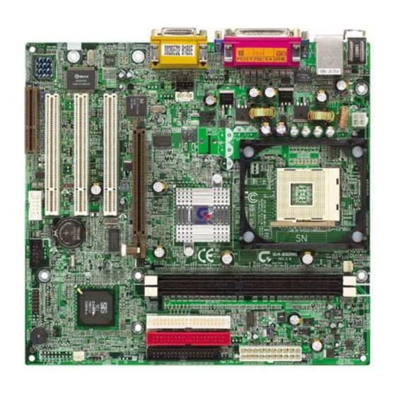
Page 10: Ga-8Siml Motherboard Layout
GA-8SIML Motherboard Layout KB_MS ATX_12V SiS 650GX***/ SiS 650** F_AUDIO* GA-8SIML SPDIF** AC97 S_IRQ** BIOS_W P*** BIOS *For PCB 1.1& 2.0 ver only **For PCB 1.0& 1.1 ver only ***For PCB 2.0 ver only DIMM_LED CPU_FAN SOCKET478 PCI1 SiS 961... -
Page 11: Chapter 2 Hardware Installation Process
Step 3- Install expansion cards Step 4- Connect ribbon cables, cabinet wires, and power supply Step 5- Setup BIOS software Step 6- Install supporting software tools Step4 Step 4 Step3 GA-8SIML Motherboard Step1 Step 2 Step 4 - 8 -... -
Page 12: Step 1: Install The Central Processing Unit (Cpu)
Step 1: Install the Central Processing Unit (CPU) Step1-1 : CPU Installation Pin1 indicator CPU Top View Socket Actuation Lever 1. Pull up the CPU socket lever and up to 90-degree angle. 3. Press down the CPU socket lever and finish CPU installation. M Please make sure the CPU type is supported by the motherboard. -
Page 13: Step1-2 : Cpu Heat Sink Installation
M Make sure the CPU fan power cable is plugged in to the CPU fan connector, this completes the installation. M Please refer to CPU heat sink user’ s manual for more detail installation procedure. GA-8SIML Motherboard 2. Hook the other end of the cooler bracket to the CPU socket. -
Page 14: Step 2: Install Memory Modules
Step 2: Install memory modules The motherboard has 2 dual inline memory module (DIMM) sockets. The BIOS w ill automatically detects memory type and si z e. To install the memory module, just push it vertically into the DIMM Slot .The DIMM module can only fit in one direction due to the notch. -
Page 15: Step 3: Install Expansion Cards
7. Power on the computer, if necessary, setup BIOS utility of expansion card from BIOS. 8. Install related driver from the operating system. AGP Card GA-8SIML Motherboard Please carefully pull out the small white- drawable bar at the end of the AGP slot when you try to install/ Uninstall the AGP card. -
Page 16: Step 4: Connect Ribbon Cables, Cabinet Wires, And Power Supply
Step 4: Connect ribbon cables, cabinet wires, and power supply Step4-1:I/O Back Panel Introduction u PS/2 Keyboard and PS/2 Mouse Connector PS/2 Mouse Connector (6 pin Female) PS/2 Keyboard Connector (6 pin Female) v USB & LAN Connector USB 0 USB 1 ØThis connector supports standard PS/2 keyboard and PS/2 mouse. -
Page 17: Audio Connectors
Audio Connectors MIC In Line Out Line In GA-8SIML Motherboard ØThis connector supports 1 standard COM port ,1 Parallel port and 1 VGA port. Device like printercan be connected to Parallel port ; mouse and modem etc can be connected to Serial ports. -
Page 18: Step 4-2 : Connectors Introduction
Step 4-2 : Connectors Introduction A) ATX_12V B) CPU_FAN C) ATX D) IDE1/IDE2 E) FLOPPY F) IR** G) CLR_CMOS*** H) SYS_FAN I) CI J) F_PANEL *For PCB 1.1& 2.0 ver only **For PCB 1.0& 1.1 ver only ***For PCB 2.0 ver only K) F_USB L) BATTERY M) COMB... - Page 19 B ) CPU_FAN (CPU FAN Connector) H ) SYS_FAN (System FAN Connector) Sense +12V/Control I) CI (CASE OPEN) GA-8SIML Motherboard ØThis connector (ATX +12V) suppliesthe CPU operation voltage (Vcore). If this " ATX+ 12V connector" is not connected, system cannot boot.
- Page 20 E ) FDD (Floppy Connector) D ) IDE1/ IDE2 (IDE1/IDE2 Connector) Q) F_AUDIO (Front Audio Connector)* Front Audio (R) Rear Audio (R) Front Audio (L) Rear Audio (L) *For PCB 1.1& 2.0 ver only **For PCB 1.0& 1.1 ver only ***For PCB 2.0 ver only Ø...
- Page 21 *For PCB 1.1& 2.0 ver only **For PCB 1.0& 1.1 ver only **For PCB 2.0 ver only GA-8SIML Motherboard Ø The SPDIF output is capable of providing digital audio to external speakers or com pressed AC3 data to an external Dolby Digital Decoder.
- Page 22 C ) ATX (ATX Power) +12V 5V SB (Stand by +5V) Power Good 3.3V 3.3V J) F_USB (Front USB Connector) F)IR ** VCC(+5V) IR Data Input IR Data Output *For PCB 1.1& 2.0 ver only **For PCB 1.0& 1.1 ver only **For PCB 2.0 ver only Ø...
- Page 23 *For PCB 1.1& 2.0 ver only **For PCB 1.0& 1.1 ver only **For PCB 2.0 ver only GA-8SIML Motherboard Ø Please note, To flash/upgrade BIOS on this MB BIOS_WP must be set to 2-3 close. We recommend BIOS_WP to be set to "1-2 close", whenever user does not need to flash/upgrade the BIOS.
-
Page 24: 2X7 Pins Jumper
J) F_PANEL (2x7 pins jumper) HD (IDE Hard Disk Active LED) Pin 1: LED anode(+) SPK (Speaker Connector) RST (Reset Switch) PD+/PD_G-/PD_Y-(Power LED) Pin 1: LED anode(+) PW (Soft Power Connector) Ø Please connect the power LED, PC speaker, reset switch and power switch etc of your chassis front panel to the F_PANEL connector according to the pin assignment above. -
Page 25: Chapter 3 Bios Setup
Restore the previous CMOS value from CMOS, only for Option Page Setup Menu <F6> Load the file-safe default CMOS value from BIOS default table <F7> Load the Optimized Defaults <F8> Dual BIOS/Q-Flash function <F9> Reserved <F10> Save all the CMOS changes, only for Main Menu GA-8SIML Motherboard - 22 -... -
Page 26: Getting Help
The Main Menu (For example: BIOS Ver. :FC) If you want detail data setting before “BIOS ver FC“, please download the manual from Gigabyte web http://www.gigabyte.com.tw. Once you enter Award BIOS CMOS Setup Utility, the Main Menu (Figure 1) will appear on the screen. -
Page 27: Integrated Peripherals
Change, set, or disable password. It allows you to limit access to the system. Save & Exit Setup Save CMOS value settings to CMOS and exit setup. Exit Without Saving Abandon all CMOS value changes and exit setup. GA-8SIML Motherboard - 24 -... -
Page 28: Standard Cmos Features
Standard CMOS Features CMOS Setup Utility -Copy right (C) 1984-2002 Aw ard Softw are Standard CMOS Features Date (mm:dd:y y ) Time (hh:mm:ss) }IDE Primary Master }IDE Primary Slav e }IDE Secondary Master }IDE Secondary Slav e Driv e A Driv e B Floppy 3 Mode Support Halt On... - Page 29 3.5 inch double-sided driv e; 720K by te capacity 81.44M, 3.5 in. 3.5 inch double-sided driv e; 1.44M by te capacity . 82.88M, 3.5 in. 3.5 inch double-sided driv e; 2.88M by te capacity . GA-8SIML Motherboard - 26 -...
-
Page 30: Base Memory
C Floppy 3 Mode Support (for J apan Area) Normal Floppy Driv e. (Default v alue) 8Disabled 8Driv e A Driv e A is 3 mode Floppy Driv e. 8Driv e B Driv e B is 3 mode Floppy Driv e. Driv e A &... -
Page 31: Advanced Bios Features
C First / S econd / Third Boot Device This feature allows you to select the boot device priority. Select y our boot dev ice priority by Floppy . 8Floppy GA-8SIML Motherboard [Auto] Item Help [Floppy ] Menu Lev el u... -
Page 32: Password Check
Select y our boot dev ice priority by LS120. 8LS120 Select y our boot dev ice priority by HDD-0~3. 8HDD-0~3 Select y our boot dev ice priority by SCSI. 8SCSI Select y our boot dev ice priority by CDROM. 8CDROM Select y our boot dev ice priority by ZIP. - Page 33 S.M.A.R.T. stands for Self-Monitoring and Analysis Reporting Technology which allows your hard disk drive to report any read/write errors and issue a warning with LDCM installed. Enable HDD S.M.A.R.T. Capability . 8Enabled Disable HDD S.M.A.R.T. Capability . (Default v alue) 8Disabled GA-8SIML Motherboard - 30 -...
-
Page 34: Advanced Chipset Features
Advanced Chipset Features We would not suggest you change the chipset default setting unless you really need it. CMOS Setup Utility -Copy right (C) 1984-2002 Aw ard Softw are Adv anced Chipset Features Top Performance Configure DRAM Timing x CAS Latency Setting x DRAM RAS Activ e Time x DRAM RAS Precharge Time x DRAM RAS to CAS Delay... -
Page 35: Dram Ras To Cas Delay
AGP Aperture Size is 8MB. 88MB AGP Aperture Size is 16MB. 816MB AGP Aperture Size is 32MB. 832MB AGP Aperture Size is 64MB. (Default v alue) 864MB AGP Aperture Size is 128MB. 8128MB AGP Aperture Size is 256MB. 8256MB GA-8SIML Motherboard - 32 -... -
Page 36: Integrated Peripherals
Integrated Peripherals CMOS Setup Utility -Copy right (C) 1984-2002 Aw ard Softw are Integrated Peripherals IDE1 Conductor Cable IDE2 Conductor Cable On-Chip Primary PCI IDE On-Chip Secondary PCI IDE AC97 Audio AC97 Modem Sy stem share Memory Size USB Controller USB Legacy Support Onboard LAN Function Init Display First... -
Page 37: Ac97 Audio
BIOS w ill search MC97 Codec (AMR Modem Card). If found, MC97 function 8Enabled w ill be enabled. If no MC97 Codec found, MC97 function w ill be disabled. (Default Value) Disable this function. 8Disabled GA-8SIML Motherboard - 34 -... -
Page 38: Usb Controller
C Share Memory Size 84MB/8MB/16MB/32MB/64MB Set onchip VGA shared memory size.(Default Value:32MB) C USB Controller Disable this option if you are not using the onboard USB feature. Enable USB Controller. (Default v alue) 8Enabled Disable USB Controller. 8Disabled C USB Legacy Support Enable USB Legacy Support. -
Page 39: Onboard Parallel Port
Using Parallel port as ECP & EPP mode. 8ECP+EPP C EPP Vers ion This feature allows you to select the EPP type version. 8EPP 1.9 Compliant w ith EPP 1.9 v ersion. 8EPP 1.7 Compliant w ith EPP 1.7 v ersion.(Default Value) GA-8SIML Motherboard - 36 -... - Page 40 C Parallel Port DMA This feature allows you to select Direct Memory Access(DMA) channel if the ECP mode selected. Set Parallel Port DMA to 3.(Default Value) Set Parallel Port DMA to 1. C OnBoard Game Port This feature allows you to select the game port address or disable it. Disable OnBoard Game Port.
-
Page 41: Power Management Setup
Set MODEM Use IRQ to Auto. (Default v alue) 8AUTO Set MODEM Use IRQ to 3. Set MODEM Use IRQ to 4. Set MODEM Use IRQ to 5. Set MODEM Use IRQ to 7. GA-8SIML Motherboard [S1(POS)] Item Help [AUTO] Menu Lev el u [Off]... - Page 42 Set MODEM Use IRQ to 9. Set MODEM Use IRQ to 10. Set MODEM Use IRQ to 11. C Soft-off by Power Button The user press the pow er button once, he can turn off the sy stem. 8Off (Default Value) The user press the pow er button once, then he can enter suspend mode.
-
Page 43: Resume By Alarm
Enable alarm function to POWER ON sy stem. 8Enabled If RTC Alarm Lead To Pow er On is Enabled. Month Alarm : Day (of Month) : 1~31 Time ( hh: mm: ss) : (0~23) : (0~59) : (0~59) GA-8SIML Motherboard NA, 1~31 - 40 -... -
Page 44: Pnp/Pci Configurations
PnP/PCI Configurations CMOS Setup Utility -Copy right (C) 1984-2002 Aw ard Softw are PnP/PCI Configurations Resources Controlled By IRQ Resources PCI1 IRQ Assignment PCI2 IRQ Assignment PCI3 IRQ Assignment higf: Mov e Enter:Select +/-/PU/PD:Value F10:Sav e F5:Prev ious Values F6:Fail-Safe Defaults Figure 7: PnP/PCI Configurations C Resources Controlled By User can set the PnP resource (I/O Address, IRQ &... - Page 45 C PCI2 IRQ Assignment Auto assign IRQ to PCI2. (Default v alue) 8Auto Set IRQ 3,4,5,7,9,10,11,12,14,15 to PCI1/5. 83,4,5,7,9,10,11,12,14,15 C PCI3 IRQ Assignment Auto assign IRQ to PCI3. (Default v alue) 8Auto Set IRQ 3,4,5,7,9,10,11,12,14,15 to PCI2/6. 83,4,5,7,9,10,11,12,14,15 GA-8SIML Motherboard - 42 -...
-
Page 46: Pc Health Status
PC Health Status CMOS Setup Utility -Copy right (C) 1984-2001 Aw ard Softw are PC Health Status Reset Case Open Status Case Status VCORE +3.3V +12V Current Sy stem Temp. Current CPU Temperature Current CPU FAN Speed Current Sy stem FAN Speed CPU Warning Temperature Sy stem FAN Fail Warning CPU FAN Fail Warning... -
Page 47: Current System Temperature
890°C / 194°F Monitor CPU Temp. at 90°C / 194°F. Disable this function.(Default v alue) 8Disabled C Fan Fai l Alarm CPU/ System Fan Fail Alarm Function Disable. (Default Value) Fan Fail Alarm Function Enable. 8Yes GA-8SIML Motherboard - 44 -... -
Page 48: Frequency/Voltage Control
Frequency/Voltage Control CMOS Setup Utility -Copy right (C) 1984-2002 Aw ard Softw are Frequency /Voltage Control CPU Clock Ratio Linear Frequency Control CPU Clock DRAM Clock (MHz) AGP Clock (MHz) PCI Clock (MHz) higf: Mov e Enter:Select +/-/PU/PD:Value F10:Sav e F5:Prev ious Values F6:Fail-Safe Defaults Figure 9: Frequency /Voltage Control... - Page 49 This feature allows you to adjust the PCI frequency, When "Linear Frequency Control" is set to Enabled. 8Please set PCI Clock according to y our requirement. Incorrect using it may cause y our sy stem broken. For pow er End-User use only ! GA-8SIML Motherboard - 46 -...
-
Page 50: Load Fail-Safe Defaults
Load Fail-Safe Defaults CMOS Setup Utility -Copy right (C) 1984-2002 Aw ard Softw are }Standard CMOS Features }Adv anced BIOS Features }Adv anced Chipset Features }Integrated Peripherals }Pow er Management Setup Load Fail-Safe Defaults? (Y/N)?Y }PnP/PCI Configurations }PC Health Status ESC:Quit F8: Q-Flash Load Fail-Safe Defaults... -
Page 51: Load Optimized Defaults
Figure 11: Load Optimized Defaults Load Optimized Defaults Selecting this field loads the factory defaults for BIOS and Chipset Features which the system automatically detects. GA-8SIML Motherboard }Frequency /Voltage Control Load Fail-Safe Defaults Load Optimized Defaults Set Superv isor Passw ord Set User Passw ord Sav e &... -
Page 52: Set Supervisor/User Password
Set Supervisor/User Password CMOS Setup Utility -Copy right (C) 1984-2002 Aw ard Softw are }Standard CMOS Features }Adv anced BIOS Features }Adv anced Chipset Features }Integrated Peripherals }Pow er Management Setup }PnP/PCI Configurations Enter Password: }PC Health Status ESC:Quit F8: Q-Flash Change/Set/Disable Passw ord Figure 12: Passw ord Setting When you select this function, the fol l owing message will appear at the center of the screen to assist... -
Page 53: Save & Exit Setup
Figure 13: Sav e & Ex it Setup Type “Y” will quit the Setup Utility and save the user setup value to RTC CMOS. Type “N” will return to Setup Utility. GA-8SIML Motherboard }Frequency /Voltage Control Load Fail-Safe Defaults Load Optimized Defaults... -
Page 54: Exit Without Saving
Exit Without Saving CMOS Setup Utility -Copy right (C) 1984-2002 Aw ard Softw are }Standard CMOS Features }Adv anced BIOS Features }Adv anced Chipset Features }Integrated Peripherals }Pow er Management Setup }PnP/PCI Configurations Quit Without Saving ( Y/N)? N }PC Health Status ESC:Quit F8: Q-Flash Abandon all Data... -
Page 55: Chapter 4 Technical Reference
AGPCLK (66MHz) 3 P C I AC97 CODEC PCICLK (33MHz) PCICLK (33MHz) USBCLK (48MHz) 14.318 MHz 33 MHz GA-8SIML Motherboard Pentium 4 CPUCLK+/- (100MHz) Socket 478 100/133MHz SiS 650/650GX ZCLK (66MHz) HCLK+/- (100MHz) 66 MHz 33 MHz 14.318 MHz 48 MHz... -
Page 56: Q-Flash Introduction
Q-Flash Introduction A. What is Q-Flash Utility? Q-Flash utility is a pre-O.S. BIOS flash utility enables users to update its BIOS within BIOS mode, no more fooling around any OS. B. How to use Q-Flash? a. After power on the computer, pressing <Del> immediately during POST (Power On Self Test) it will allow you to enter AWARD BIOS CMOS SETUP, then press <F8>... - Page 57 !Press Enter to Run. !! COPY BIOS Completed -Pass !! Please press any key to continue Congratulation! You have completed the flashed and now can restart system. GA-8SIML Motherboard 1 File(s) found Free Size: 1.14M DEL: Delete ESC: Return Main...
-
Page 58: Bios Introduction
BIOS directly. Or you may want to keep a backup for your current BIOS, just choose “Save Current BIOS” to save it first. You make a wise choice to use Gigabyte, and @BIOS update your BIOS smartly. You are now worry free from updating wrong BIOS, and capable to maintain and manage your BIOS easily. -
Page 59: Easytuneiii
Now everything is different because of a Windows overdrive utility EasyTuneIII—announced by Gigabyte. This utility has totally changed the gaming rule of “overdrive”. This is the first overdrive utility suitable for both normal and power users. Users can choose either “Easy Mode” or “Advanced Mode”... -
Page 60: Chapter 5 Appendix
Revision History Chapter 5 Appendix Picture below are shown in Windows XP (TUCD driver version 2.0) Appendix A: SiS 650/650GX Chipset Driver Installation (Must Install!) A. SiS 650/650GX VGA Driver Installation Insert the driver CD-title that came with your motherboard into your CD-ROM driver, the driver CD-title will auto start and show the installation guide. - Page 61 CD-title will auto start and show the installation guide. If not, please double click the CD-ROM device icon in "My computer", and execute the setup.exe. 1.Click "SiS AGP Driver item. 3.Click "Next". 2.Click "Next". 4.Click "Finish" to restart computer. GA-8SIML Motherboard - 5 8 -...
- Page 62 C: USB Patch Driver Driver Installation 2.Click "Finish" to restart computer. 1.Click "USB Patch Driver" item. - 5 9 - Appendix...
- Page 63 Appendix B: SiS 7012 Sound Driver 2.Click "Next". 1.Click "SiS 7012 Audio Driver" item. 4.Click "Finish" to restart computer. 3.Click "Next". GA-8SIML Motherboard - 6 0 -...
- Page 64 Appendix C: RealTek 8100/8139 Network Driver Revision History "RealTek 8100/8139 Network Driver" under Windows ME will auto install. If you would like to install LAN driver, please refer to attached README.txt file for detail instruction. Please install the driver through CD-ROM by the path D:\Network\Rtl (This manual assumes that your CD-ROM device drive letter is D:).
- Page 65 Insert the driver CD-title that came with your motherboard into your CD-ROM driver, the driver CD-title will auto start and show the installation guide. If not, please double click the CD-ROM device icon in "My computer", and execute the setup.exe. Press "Tools" icon. 1.Click "Gigabyte Utilities". 3.Click "Next". 5.Click "Next". GA-8SIML Motherboard 2.Click "Easy Tune III Setup".
- Page 66 7.Click "Finish" to restart computer. - 6 3 - Appendix...
- Page 67 Appendix E: BIOS Flash Procedure BIOS update procedure: If your OS is Win9X, we recommend that you used Gigabyte @BIOS Press "Tools" icon. 1.Click "Gigabyte Utilities". Click "!". Click here. Methods and steps: I. Update BIOS through Internet a. Click "Internet Update" icon b.
- Page 68 Otherwise, your system won't boot. c. In method I, if the BIOS file you need cannot be found in @BIOS Gigabyte's web site for downloading and updating it according to method II. d. Please note that any interruption during updating will cause system unbooted...
- Page 69 (1) With an available floppy disk in the floppy drive. Please leave the diskette "UN-write protected" type. Double click the "My Computer" icon from Desktop, then click "3.5 diskette (A)" and right click to select "Format (M)" GA-8SIML Motherboard - 6 6 -...
- Page 70 (2) Select the "Quick (erase)" for Format Type, and pick both "Display summary when finished" and "Copy system files", after that press "Start". That will format the floppy and transfer the needed system files to it. Beware: This procedure will erase all the prior data on that floppy, so please proceed accordingly. (3) After the floppy has been formatted completely, please press "Close".
- Page 71 STEP 3: Download BIOS and BIOS utility program. (1) Please go to Gigabyte website http://www.gigabyte.com.tw/index.html, and click "Support". (2) From Support zone, click the "Motherboards BIOS & Drivers". GA-8SIML Motherboard - 6 8 -...
- Page 72 (3) We use GA-7VTX motherboard as example. Please select GA-7VTX by Model or Chipset optional menu to obtain BIOS flash files. (4) Select an appropriate BIOS version (For example: F4), and click to download the file. It will pop up a file download screen, then select the "Open this file from its current location" and press "OK". - 6 9 - Appendix...
- Page 73 (5) At this time the screen shows the following picture, please click "Extract" button to unzip the files. (6) Please extract the download files into the clean bootable floppy disk A mentioned in STEP 2, and press "Extract". GA-8SIML Motherboard - 7 0 -...
- Page 74 STEP 4: Make sure the system will boot from the floppy disk. (1) Insert the floppy disk (contains bootable program and unzip file) into the floppy drive A. Then, restart the system. The system will boot from the floppy disk. Please press <DEL> key to enter BIOS setup main menu when system is boot up.
- Page 75 F 6 : L o a d B I O S D e f a u l t s Save Data to CMOS & Exit SETUP GA-8SIML Motherboard : F l o p p y : I D E - 0...
- Page 76 STEP 5: BIOS flashing. (1) After the system boot from floppy disk, type "A:\> dir/w" and press "Enter" to check the entire files in floppy A. Then type the "BIOS flash utility" and "BIOS file" after A:\>. In this case you have to type "A:\>...
- Page 77 Are you sure to flash the BIOS? [Enter] to continue Or [Esc] to cancel? (4) The BIOS flash completed. Please press [ESC] to exit Flash Utility. [Enter] to continue Or [Esc] to cancel? GA-8SIML Motherboard EXIT? - 7 4 -...
- Page 78 STEP 6: Load BIOS defaults. Normally the system redetects all devices after BIOS has been upgraded. Therefore, we highly recommend reloading the BIOS defaults after BIOS has been upgraded. This important step resets everything after the flash. (1) Take out the floppy diskette from floppy drive, and then restart the system. The boot up screen will indicate your motherboard model and current BIOS version.
- Page 79 F 6 : L o a d B I O S D e f a u l t s Save Data to CMOS & Exit SETUP (4) Congratulate you have accomplished the BIOS flash procedure. GA-8SIML Motherboard INTEGRATED PERIPHERALS HARDWARE MONITOR & MISC SETUP...
- Page 80 Appendix D: Acronyms Acronyms Meaning ACPI Advanced Configuration and Power Interface Advanced Power Management Accelerated Graphics Port Audio Modem Riser Advanced Communications Riser BIOS Basic Input / Output System Central Processing Unit CMOS Complementary Metal Oxide Semiconductor CRIMM Continuity RIMM Communication and Networking Riser Direct Memory Access Desktop Management Interface...
- Page 81 Power-On Self Test Peripheral Component Interconnect RIMM Rambus in-line Memory Module Special Circumstance Instructions SECC Single Edge Contact Cartridge SRAM Static Random Access Memory Symmetric Multi-Processing System Management Interrupt Universal Serial Bus Voltage ID GA-8SIML Motherboard - 7 8 -...
- Page 82 Technical Support/RMA Sheet Customer/Country: Contact Person: E-mail Add. : Model name/Lot Number: BIOS version: O.S./A.S.: Hardware Mfs. Model name Configuration Memory Brand Video Card Audio Card CD-ROM / DVD-ROM Modem Network AMR / CNR Keyboard Mouse Power supply Other Device Problem Description: Company: Phone No.:...
Need help?
Do you have a question about the GA-8SIML and is the answer not in the manual?
Questions and answers