Table of Contents
Advertisement
Quick Links
Download this manual
See also:
User Manual
Advertisement
Table of Contents

Subscribe to Our Youtube Channel
Related Manuals for SOYO SY-K7ADA


Summary of Contents for SOYO SY-K7ADA
- Page 1 SY-K7ADA Motherboard **************************************************** ® Athlon/Duron Processor supported ALI MAGIK1 AGP/PCI Motherboard 266/200 MHz Front Side Bus supported ATX Form Factor **************************************************** User's Manual...
- Page 2 It is the policy of Soyo Computer Inc. to respect the valid patent rights of third parties and not to infringe upon or to cause others to infringe upon such rights.
-
Page 3: Table Of Contents
Table of Contents SY-K7ADA Table of Contents CHAPTER 1 MOTHERBOARD DESCRIPTION.......1 INTRODUCTION ............1 KEY FEATURES .............1 ELECTROSTATIC DISCHARGE PRECAUTIONS ..4 SY-K7ADA MOTHERBOARD LAYOUT .......5 SY-K7ADA M ......6 OTHERBOARD OMPONENTS MICROPROCESSOR............8 CHIPSET .................9 HARDWARE MONITOR..........12 WAKE ON LAN TECHNOLOGY........13 CHAPTER 2 HARDWARE INSTALLTION........14 PREPARATIONS ............14... - Page 4 Table of Contents SY-K7ADA ADVANCED BIOS FEATURES........54 ADVANCED CHIPSET FEATURES......59 INTEGRATED PERIPHERALS ........62 POWER MANAGEMENT SETUP ........66 PNP/PCI CONFIGURATION SETUP......70 PC HEALTH STATUS............73 LOAD FAIL-SAFE DEFAULTS........75 LOAD OPTIMIZED DEFAULTS........76 3-10 SUPERVISOR PASSWORD...........77 3-11 USER PASSWORD............78 3-12 IDE HDD AUTO DETECTION ........79 3-13 BOOT MENU ..............80...
-
Page 5: Chapter 1 Motherboard Description
New released AMD Socket 462 CPUs will very likely be supported by the SY-K7ADA as well. Ø CPU SETTINGS The SY-K7ADA provides the user with a very complete and convenient CPU setting environment. The CPU settings are all adjusted through the DIP switch. CPU Frequency... - Page 6 Motherboard Description SY-K7ADA CPU Multiplier Ø EXPANDABILITY The SY-K7ADA provides all the standard expansion slots, and many more additional expansion features: Expansion slots 1 x 32-bit bus master AGP slot 5 x 32-bit bus master PCI slots Enhanced IO Floppy disk controller...
-
Page 7: Hardware Monitor
FLOPPY DRIVE & HDD, LS120, SCSI, ZIP. Power on by modem or alarm If the SY-K7ADA system is in suspend mode, it can be switched back on through the modem or RTC alarm function. This opens a lot of possibilities, such as remote access that switches the system on only after the modem receives a call. -
Page 8: Electrostatic Discharge Precautions
Motherboard Description SY-K7ADA CPU FSB frequency PCI clock AGP Clock SDRAM Clock Ø HANDLING THE MOTHERBOARD To avoid damage to your Motherboard, follow these simple rules while unpacking: Ø Before handling the Motherboard, ground yourself by grasping an unpainted portion of the system's metal chassis. -
Page 9: Sy-K7Ada Motherboard Layout
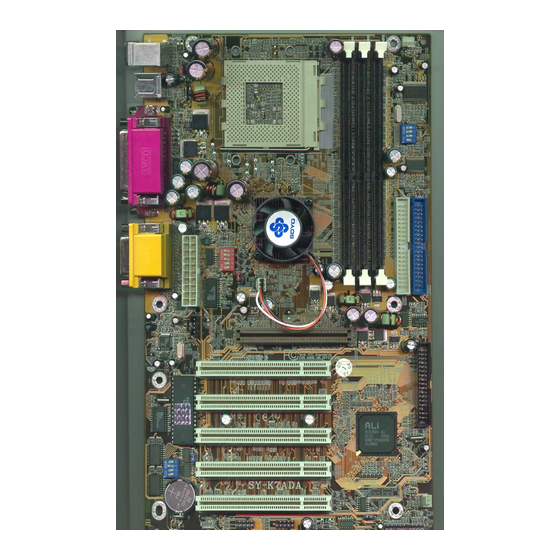
Motherboard Description SY-K7ADA 1-4 SY-K7ADA MOTHERBOARD LAYOUT PS/2 KB PS/2 Mouse Connector Connector USB 1_2 COMA COMB AGAME SDRAM ATX Power ® AOUT M1647 SDRAM AMIC IDE 2 IDE 1 M5879 AGP Slot Sigmatel STAC9700 CDIN1 PCI Slot #1 PCI Slot #2... -
Page 10: Sy-K7Ada Motherboard Components
Motherboard Description SY-K7ADA 1-5 SY-K7ADA MOTHERBOARD COMPONENTS SDRAM ® SDRAM... - Page 11 Motherboard Description SY-K7ADA K/B Power-On setting Jumper CPU Vcore adjustment setting switch Socket 462 Connector DIMM Banks CPU Cooling Fan Connector CPU FSB adjustment setting switch Bus Mastering E-IDE/ATAPI Ports ALi M1647 North Bridge chip SYS Cooling Fan CPU Vcore setting Jumper...
-
Page 12: Microprocessor
Motherboard Description SY-K7ADA 1-6 MICROPROCESSOR The motherboard supports a single Socket 462 processor. The processor’s VID pins automatically program the voltage regulator on the motherboard to the required processor voltage. In addition, the front side bus speed (200/266 MHz ) is automatically selected. The motherboard supports all current Socket 462 processor speeds, voltages, and bus frequencies. -
Page 13: Chipset
Motherboard Description SY-K7ADA CHIPSET Ø ALi M1647 Overview The M1647 is a high performance, high value North Bridge that supports all Athlon family processors. Internally all 128-bit architecture with optimization for S2K bus, DDR and AGP4X interface, the M1647 has outstanding high system performance under all types of system operations. - Page 14 Motherboard Description SY-K7ADA This boosts the graphic benchmarks into another era for professional graphics usage. The M1647 design is capable of supporting 28 outstanding AGP commands (depth of command queue=28) and buffering 64QW for AGP master read operations. The M1647 is fully compliant with the PCI 2.2 specification. Flexible PCI latency control allows the M1647 to achieve improved system performance.
- Page 15 Motherboard Description SY-K7ADA three full function universal asynchronous receiver/transmitters (UARTs), a flexible high performance internal data separator with send/receive 16 byte FIFOs. It is also suitable for notebook computers since it has Fast Infra Red for wireless communications with other devices. It can swap the floppy drives A &...
-
Page 16: Hardware Monitor
Motherboard Description SY-K7ADA Legacy-Free and Legacy Reduction specification of PC2001. 1-7.1 PS/2 Keyboard and Mouse Interface PS/2 keyboard and mouse connectors are located on the back panel of the motherboard. The +5 V lines to keyboard and mouse connectors are protected with a fuse that prevents motherboard components from being damaged when an over-current condition occurs. -
Page 17: Wake On Lan Technology
Motherboard Description SY-K7ADA 1-9 WAKE ON LAN TECHNOLOGY Wake on LAN technology enables remote wakeup of the computer through a network. Wake on LAN technology requires a PCI add-in network interface card (NIC) with remote wakeup capabilities. The remote wakeup connector on the NIC must be connected to the onboard Wake on LAN connector. -
Page 18: Chapter 2 Hardware Installtion
SY-K7ADA Chapter 2 HARDWARE INSTALLATION Congratulations on your purchase of SY-K7ADA Motherboard. You are about to install and connect your new Motherboard. Note: Do not unpack the Motherboard from its protective anti- static packaging until you have made the following preparations. -
Page 19: Unpacking The Motherboard
Hardware Installation SY-K7ADA UNPACKING THE MOTHERBOARD When unpacking the Motherboard, check for the following items: The SY-K7ADA ALi MAGIK1 AGP/PCI Motherboard The Quick Start Guide The Installation CD-ROM SOYO Bonus Pack CD-ROM One IDE Device ATA33/66/100 Flat Cable One Floppy Disk Drive Flat Cable... -
Page 20: Installation Guide
Hardware Installation SY-K7ADA 2-3 INSTALLATION GUIDE We will now begin the installation of the Motherboard. Please follow the step-by-step procedure designed to lead you to a complete and correct installation. Warning: Turn off the power to the Motherboard, system chassis, and peripheral devices before performing any work on the Motherboard or system. -
Page 21: 2-3.1 Cpu Installation
Hardware Installation SY-K7ADA 2-3.1 CPU Installation Your SY-K7ADA motherboard comes with a CPU retention set kit. The retention set is used to hold the processor attached to the Socket 462 CPU connector on the motherboard. Record the working frequency of Mark your CPU Frequency: your CPU that should be clearly marked on the CPU cover. - Page 22 Hardware Installation SY-K7ADA Align the blunt edge of the CPU with the matching pinhole distinctive edge on the socket. Seat the processor in the socket completely and without forcing. Then close the socket handle to secure the CPU in place.
- Page 23 Hardware Installation SY-K7ADA Remember to connect the CPU Cooling Fan to the appropriate power connector on the Motherboard. The fan is a key component that will ensure system stability. The fan prevents overheating, therefore prolonging the life of your CPU.
-
Page 24: 2-3.2 Ddr Sdram Memory Module Installation
Hardware Installation SY-K7ADA 2-3.2 DDR SDRAM Memory Module Installation SDRAM ® SDRAM Your board comes with three DIMM sockets, providing support for up to 3GB of main memory using DDR RAM modules from 4Mb to 512Mb. On this motherboard, DRAM speed can be set independent from the CPU front side bus speed. - Page 25 Hardware Installation SY-K7ADA Memory Configuration Table Number of Memory DIMM 1 DIMM 2 DIMM 3 Modules RAM Type DDR SDRAM Memory Module Size 4/16/32/64/128/256/512 Mbit...
-
Page 26: 2-3.3 Motherboard Connector
Hardware Installation SY-K7ADA 2-3.3 Motherboard Connector SDRAM ® SDRAM Pin-1 IDE 2 IDE 1 Secondary Primary 2-3.3.1 IDE Device Installation (HDD, CD-ROM) This Motherboard offers two primary and secondary IDE device connectors (IDE1, IDE2). It can support up to four high-speed Ultra DMA 33/66/100HDD or CD-ROM. -
Page 27: Floppy Drive Installation
Hardware Installation SY-K7ADA 2-3.3.2 Floppy Drive Installation SDRAM ® SDRAM Pin -1 Floppy Drive Connector The system supports 5 possible floppy drive types: 720 KB, 1.2 MB, 1.44 MB, 2.88 MB, and LS-120. Connect one side of the 34-pin flat cable to the floppy drive and plug the other end to the floppy drive connector on the Motherboard. - Page 28 Hardware Installation SY-K7ADA 2-3.3.3 Front Panel Connections SDRAM 1112 13 14 15 16 17 18 19 20 ® SDRAM 1 2 3 4 5 9 10 Plug the computer case's front panel devices to the corresponding headers on the Motherboard.
- Page 29 Hardware Installation SY-K7ADA 2. Reset Plug the Reset push-button cable into the 2-pin Reset header on the Motherboard. Pushing the Reset button on the front panel will cause the system to restart the boot-up sequence. Reset Pin Assignment Pin1 Pin2 Power RST 3.
- Page 30 Hardware Installation SY-K7ADA 5. ATX Power On/Off Switch Attach the 2-pin momentary type switch to the PWRBT header for turning On or Off your ATX power supply. PWRBT Pin Assignment Pin4 Pin5 PWRBTN...
- Page 31 Hardware Installation SY-K7ADA 2-3.3.4 Back Panel Connections All external devices such as the PS/2 keyboard, PS/2 mouse, printer, modem, USB1, USB2 can be plugged directly onto the Motherboard back panel. Only after you have fixed and locked the Motherboard to the computer case can you start connecting the external peripheral devices.
- Page 32 Hardware Installation SY-K7ADA 1. Onboard Serial Ports COM1/COM2 External peripherals that use serial transmission scheme include: serial mouse, and modem. Plug the serial device cables directly into the COM1/COM2 9-pin male connectors located at the rear panel of the Motherboard.
- Page 33 Hardware Installation SY-K7ADA 5. Universal Serial Bus (USB3, USB4/USB5, USB6) This Motherboard provides four USB ports for your additional devices. Plug the USB device jack into the available USB connector USB3, USB4, USB5 and USB6 via USB cable. Standard device drivers come with the Win98 for commonly used USB devices.
- Page 34 Hardware Installation SY-K7ADA 2-3.3.5 Other Connections 1. Wake-On-LAN (WOL) Attach the 3-pin connector from the LAN card which supports the Wake- On-LAN (WOL) function to the JP10 header on the Motherboard. This WOL function lets users wake up the connected computer through the LAN card.
- Page 35 Hardware Installation SY-K7ADA 2. Infrared Plug infrared device cable to the SIRCON header. This will enable the infrared transfer function. This Motherboard meets both the IrDA 1.0 (SIR) and IrDA 1.1 (FIR and MIR) specifications. Supports sharp-IR. Please install according to the following pin assignment:...
- Page 36 Hardware Installation SY-K7ADA 4. Cooling Fan Installation (1) CPU Cooling Fan After you have seated the CPU properly on the processor, attach the 3-pin fan cable to the CPUFAN connector on the Motherboard. The fan will stop when the system enters into Suspend Mode. (Suspend mode can be enabled from the BIOS Setup Utility, [POWER MANAGEMENT] menu.)
- Page 37 Hardware Installation SY-K7ADA (2) Chassis Cooling Fan Some chassis also feature a cooling fan. This Motherboard features a CHAFAN connector to provide 12V power to the chassis fan. Connect the cable from the chassis fan to the CHAFAN 3-pin connector. Install...
- Page 38 Hardware Installation SY-K7ADA 5. CD Line-in (CDIN1) This Motherboard provides two CD-Line in connectors. Please connect the 4-pin audio cable from your CD-ROM drive to either CDIN1. (It fits in only one, depending on the cable that came with your CD-ROM drive)
-
Page 39: Atx Power
Hardware Installation SY-K7ADA 2-3.3.7 ATX Power Supply ATX Power SDRAM ® SDRAM Plug the connector from the power directly into the 20-pin male ATX PW connector on the Motherboard, as shown in the following figure. Warning: Follow these precautions to preserve your... -
Page 40: 2-3.4 Jumper Setting
Hardware Installation SY-K7ADA ATX Power 5VSB PW-OK Ø Pay special care to the directionality. PS-ON 3.3V -12V 3.3V 3.3V 2-3.4 Jumper Setting 2-3.4.1 Multiplier Adjustment Setting (RJ1) For certain AMD CPUs, the multiplier is not locked such that setting a multiplier higher than specified on the CPU is possible. - Page 41 CPU speed, as follow table: 10.5 11.5 12.5 Note: SOYO does not guarantee system stability if the user over clocks the system. Any malfunctions due to over-clocking are not covered by the warranty. 2-3.4.2 Enable/Disable Power-On by Keyboard (JP1) You may choose to enable the Power-On through Keyboard function by shorting pin 2-3 on jumper JP1;...
-
Page 42: 2-3.5 The Synchronous/Asynchronous Clock Mode Between
The FSB Frequency can be set through DIP switch FJ1 or BIOS and it may therefore differ from the Frequency the CPU specifies. Doing so may however force your CPU to operate out of its specifications and therefore SOYO can not guarantee the proper functioning of your system. Refer to the following table: CPU Freq(MHz) SDRAM(MHz 2-3.6 CPU Vcore adjustment (VJ1) -
Page 43: 2-3.7 Cmos Clearing (Jp5)
Hardware Installation SY-K7ADA If you set status to manual and configure VJ1 switch to the settings that match your CPU voltage as follow table: Auto OFF OFF OFF OFF OFF 1.475 OFF OFF OFF OFF ON 1.100 ON OFF OFF OFF OFF 1.500 ON OFF OFF OFF ON 1.125 OFF ON OFF OFF OFF 1.525 OFF ON OFF OFF ON... -
Page 44: 2-3.8 Power On
BIOS Setup Utility SY-K7ADA 2-3.8 Power On You have now completed the hardware installation of your Motherboard successfully. 1. Turn the power on 2. To enter the BIOS Setup Utility, press the <DEL> key while the system is performing the diagnostic checks, Note: If you have failed to enter the BIOS, wait until the boot up sequence is completed. -
Page 45: 2-3.9 Quick Bios Setup
This Motherboard does not use any hardware jumpers to set the CPU frequency. Instead, CPU settings are software configurable with the BIOS [SOYO COMBO SETUP]. The [SOYO COMBO SETUP] menu combines the main parameters that you need to configure, all in one menu, for a quick setup in BIOS. -
Page 46: 2-3.10 Troubleshooting At First Start
2-3.10 Troubleshooting at First Start Video (no display) related issues I built a new computer system using a Soyo board and nothing happens when turning it on, no video and no beeps from the PC speaker. What is happening and how can it be fixed? No screen and no beeps mean that your CPU and motherboard do not work at all. -
Page 47: Bios Issues
5EH_2CA1 (meaning revision 2CA1 for the SY-5EH board) or 6BA+ IV_2AA2 which means SY-6BA+ IV motherboard with 2AA2 bios. Where can I find the latest BIOS of my motherboard? Please go to the technical support page of one of the SOYO websites www.soyo.com.tw (Taiwan: ), and look up your motherboard to find the latest BIOS revision. -
Page 48: Audio Issues
Why? If you are sure that the modem driver has been installed correctly, then you need to install the south bridge driver from the SOYO CD, this is because Windows does not properly recognize relatively new chipsets. -
Page 49: 2-3.11 Power Off
Then put back the peripherals one by one to identify which one causes the lockup. I can not get my board to run properly. Please make sure you have the latest bios and driver from the SOYO web site at: http://www.soyo.com 2-3.11 Power Off... -
Page 50: Chapter 3 Bios Setup Utility
BIOS Setup Utility SY-K7ADA Chapter 3 BIOS SETUP UTILITY This Motherboard's BIOS setup program uses the ROM PCI/ISA BIOS program from Award Software Inc. To enter the Award BIOS program's Main Menu: 1. Turn on or reboot the system. 2. After the diagnostic checks, press the [Del] key to enter the Award BIOS Setup Utility. - Page 51 BIOS Setup Utility SY-K7ADA Hot Keys: Function keys give you access to a group of commands throughout the BIOS utility. Function Command Description Gives the list of options available for each General Help item. Previous Restore the old values. These are the values Values that the user started the current session with.
-
Page 52: Save And Exit Setup
BIOS Setup Utility SY-K7ADA SAVE AND EXIT SETUP Select the [SAVE & EXIT SETUP] option from the Main Menu to save data to CMOS and exit the setup utility. This option saves all your changes and causes the system to reboot. -
Page 53: Soyo Combo Setup
<DEL> key during the system diagnostic checks to enter the Award BIOS Setup program. The CMOS SETUP UTILITY will display on screen. Then, select the [SOYO COMBO SETUP] option from the main menu and press the <Enter> key. -
Page 54: Quick Power On Self Test
BIOS Setup Utility SY-K7ADA 3-1.1 Quick CPU Frequency Setup Setting Description Note Disabled For EMI test purpose. Auto Detect DIMM/PCI Clk Enabled Default Spread Disabled Default Spectrum Enabled When using Spread Spectrum Modulated Modulated 1.5% or 6% for FCC or DOC testing. -
Page 55: Power Management
BIOS Setup Utility SY-K7ADA 3-1.3 System Boot Control Settings System Boot Setting Description Note Control Settings First Floppy Select Your Boot Device /Second/Third Priority LS/ZIP Boot Device HDD-0 SCSI CDROM HDD-1 HDD-2 HDD-3 Disabled Disabled Select Your Boot Device Boot Other... -
Page 56: Standard Cmos Setup
BIOS Setup Utility SY-K7ADA STANDARD CMOS SETUP Select the [STANDARD CMOS SETUP] option from the Main Menu and press [Enter] key. CMOS Setup Utility – Copyright ( C ) 1984-2001 Award Software Standard CMOS Features Date (mm:dd:yy) Tue, Jan 4 2001... -
Page 57: Floppy Drives
BIOS Setup Utility SY-K7ADA 3-1.6 Hard Disks Type & Mode Choose the type and mode for the hard disks that you have already installed. Primary Setting Description Note (Secondary) Master & Slave Press To auto-detect the HDD’s size, IDE HDD Auto- Enter head …... -
Page 58: Advanced Bios Features
BIOS Setup Utility SY-K7ADA 3-1.8 Others Optional Setting Description Note EGA/VGA Select the video mode. Default Video CGA 40 CGA 80 MONO (Monochrome) Halt On ALL Errors When the BIOS detects system Default errors, this function will stop the No Errors system. -
Page 59: Virus Warning
BIOS Setup Utility SY-K7ADA After you have completed the changes, press [Esc] key and follow the instructions on your screen to save your settings or exit without saving. 3-2.1 Virus Warning Setting Description Note Disabled Allows you to choose the... -
Page 60: Boot Up Numlock Status
BIOS Setup Utility SY-K7ADA 3-2.5 Boot Up NumLock Status Setting Description Note Puts numeric keypad in Default Boot Up NumLock mode at boot-up. NumLock Status Puts numeric keypad in arrow key mode at boot-up. High Boots at default CPU speed. -
Page 61: Security Option
BIOS Setup Utility SY-K7ADA Typematic Settings Setting Description Note 250 (msec) Choose how long after Default Typematic Delay 500 (msec) you press a key down the 750 (msec) character begins 1000 (msec) repeating. 3-2.8 Security Option Use this feature to prevent unauthorized system boot-up or use of BIOS Setup. - Page 62 BIOS Setup Utility SY-K7ADA 3-2.9 Other Control Options Other Control Setting Description Note Options When using an OS2 operating OS Select for system. DRAM>64MB Non-OS2 When using another, Default non-OS2 operating system. Windows will release IRQ line 6 Default Report No FDD...
-
Page 63: Advanced Chipset Features
BIOS Setup Utility SY-K7ADA 3-3 ADVANCED CHIPSET FEATURES Caution: Change these settings only if you are already familiar with the Chipset. The [Advanced Chipset Features] option changes the values of the chipset registers. These registers control the system options in the computer. - Page 64 BIOS Setup Utility SY-K7ADA CHIPSET FEATURES SETUP (Continued) CHIPSET Setting Description Note FEATURES DRAM CAS Auto (By SPD) When synchronous Select DRAM is installed, the 2.5 (DDR) / 3 (SDR) Default number of clock cycles of 2 (DDR) / 2 (SDR) CAS latency depends on the DRAM timing.
- Page 65 BIOS Setup Utility SY-K7ADA CHIPSET FEATURES SETUP (Continued) CHIPSET Setting Description Note FEATURES AGP Aperture 128M Select the size of Accelerated Default Size Graphics Port (AGP) aperture. 4M, 8M, 16M, The aperture is portion of the 32M, 128M, PCI memory address range 256M.
-
Page 66: Integrated Peripherals
BIOS Setup Utility SY-K7ADA 3-4 INTEGRATED PERIPHERALS Caution: Change these settings only if you are already familiar with the Chipset. The [INTEGRATED PERIPHERALS] option changes the values of the chipset registers. These registers control the system options in the computer. - Page 67 BIOS Setup Utility SY-K7ADA The following tables describe each field in the INTEGRATED PERIPHERALS Menu and provide instructions on how to configure the IDE controls, FDC controls, and the onboard serial and parallel ports. 3-4.1 IDE Device Controls IDE Controls...
-
Page 68: Ide Hdd Block Mode
BIOS Setup Utility SY-K7ADA 3-4.2 Keyboard Controls Keyboard Controls Setting Description Note PCI Slot Choose which card – AGP Init Display First Display card or PCI VGA card – Default to initialize first. 3-4.3 IDE HDD Block Mode Setting Description... - Page 69 BIOS Setup Utility SY-K7ADA IrDA Default UART Mode The second serial port offers these InfraRed interface Select ASKIR modes. TFDS6000 HSDL3600 HSDL1100 Hi, Hi This item allow you to RxD, TxD Active determine the active RxD, Hi, Lo Default TxD.
-
Page 70: Power Management Setup
BIOS Setup Utility SY-K7ADA POWER MANAGEMENT SETUP The [POWER MANAGEMENT SETUP] sets the system's power saving functions. CMOS Setup Utility – Copyright ( C ) 1984-2001 Award Software Power Management Setup ACPI Suspend Type S1 (POS) Item Help Power Management... - Page 71 BIOS Setup Utility SY-K7ADA 3-5.1 Power Management Controls Power Setting Description Note Management Controls S1(POS) The system will enter the S1 Default ACPI Suspend state during suspend. (Low Type S3(STR) latency wake up) User Define Lets you define the HDD and...
- Page 72 BIOS Setup Utility SY-K7ADA Disabled Default HDD Power Down 1-15 Min When the set time has Some older model HDDs elapsed, BIOS sends a may not support command to the HDD to this advanced power down. This turns off function.
- Page 73 BIOS Setup Utility SY-K7ADA IRQ[1] Enabled Select enabled that will wake up Default your system when in one of sleep (Keyboard) Disabled modes. Enabled Select enabled that will wake up IRQ[3] your system when in one of sleep Disabled Default modes.
-
Page 74: Pnp/Pci Configuration Setup
BIOS Setup Utility SY-K7ADA Enabled Default IRQ[14] Select enabled that will wake up Disabled your system when in one of sleep modes. Enabled Select enabled that will wake up Default IRQ[15] (Secondary your system when in one of sleep Disabled IDE) modes. - Page 75 BIOS Setup Utility SY-K7ADA 3-6.1 PNP/PCI Configuration Controls PNP/PCI Setting Description Note Controls PnP OS Set this field to [Yes] if you Installed are running Windows 95, which is PnP compatible. If the OS you are running Default (If there is any...
- Page 76 BIOS Setup Utility SY-K7ADA PNP/PCI Configuration Setup (Continued) PNP/PCI Setting Description Note Setup Your OS may reassign another interrupt to a PCI slot after BIOS passes control to the OS, especially if you use Windows 95, 98 or NT. PCI/VGA Disabled Leave this field at Disabled.
-
Page 77: Pc Health Status
BIOS Setup Utility SY-K7ADA 3-7 PC HEALTH STATUS This option sets the Motherboard's PC Health Status. CMOS Setup Utility – Copyright ( C ) 1984-2001 Award Software PC Health Status CPU Warning Temperature Disabled Item Help Current SYS Temperature 31 º C / 87 º F... - Page 78 BIOS Setup Utility SY-K7ADA 3-7.1 CPU Device Monitoring CPU Device Setting Description Note Monitoring CPU Warning Disabled Default Set CPU temperature from 50 C Temperature 50 C/122 F to 70 C. The CPU will slow down when CPU temperature 53 C/127 F goes beyond the preset value.
-
Page 79: Load Fail-Safe Defaults
BIOS Setup Utility SY-K7ADA 3-8 LOAD FAIL-SAFE DEFAULTS Select the [Load Fail-Safe Defaults] option from the Main Menu to load the system values you have previously saved. This option is recommended if you need to reset the system setup and to retrieve the old values. -
Page 80: Load Optimized Defaults
BIOS Setup Utility SY-K7ADA 3-9 LOAD OPTIMIZED DEFAULTS Select the [Load Optimized Defaults] option from the Main Menu to load the system values you have previously saved. This option is recommended if you need to reset the system setup and to retrieve the old values. -
Page 81: Supervisor Password
BIOS Setup Utility SY-K7ADA 3-10 SUPERVISOR PASSWORD Based on the setting you have made in the [Security Option] of the [BIOS FEATURES SETUP] section, the password prevents access to the system or the setup program by unauthorized users. Follow this procedure to set a... -
Page 82: User Password
BIOS Setup Utility SY-K7ADA Enter your new password and press [Enter]. The following message appears, prompting to confirm the new password: Confirm Password: Re-enter your password and then press [Enter] to exit to the Main Menu. This diagram outlines the password selection procedure: Type the Password Press <Enter>... -
Page 83: Ide Hdd Auto Detection
BIOS Setup Utility SY-K7ADA 3-12 IDE HDD AUTO DETECTION This Main Menu function automatically detects the hard disk type and configures the [Standard CMOS Features] accordingly. CMOS Setup Utility – Copyright ( C ) 1984-2001 Award Software IDE Primary Master... -
Page 84: Boot Menu
BIOS Setup Utility SY-K7ADA 3-13 BOOT MENU Boot Menu enables user to boot-up on different boot device without going into the BIOS setup. To enable boot Menu, press “ESC” after memory initialization, user will see a device menu, in which user can choose the device they wish to boot from. -
Page 85: Chapter 4 Driver Installation
DRIVER INSTALLATION Your SY-K7ADA Motherboard comes with a CD-ROM labeled "SOYO CD." The SOYO CD contains the user's manual file for your new Motherboard, the drivers software available for installation, and a database in HTML format with information on SOYO Motherboards and other products. - Page 86 Drivers installation SY-K7ADA If you use Windows 95 or 98, the SOYO CD Start Up Program automatically detects which SOYO Motherboard you own and displays the corresponding model name. The user's manual files included on the SOYO CD are in PDF (Postscript Document) format.
- Page 87 Drivers installation SY-K7ADA Step 2. Install Drivers Click the Install Drivers button to display the list of drivers software that can be installed with your Motherboard. The Start Up program displays the drivers available for the particular model of Motherboard you own. We recommend that you only install those drivers.
- Page 88 Note: Once you have selected a driver, the system will automatically exit the SOYO CD to begin the driver installation program. When the installation is complete, most drivers require to restart your system before they can become active.
- Page 89 SY-K7ADA Step 4. Check the Latest Releases Click the 'Check the latest Releases' button to go the SOYO Website to automatically find the latest BIOS, manual and driver releases for your motherboard. This button will only work if your computer is connected to the internet through a network or modem connection.
Need help?
Do you have a question about the SY-K7ADA and is the answer not in the manual?
Questions and answers