Advertisement
Quick Links
Operator: Save these instructions for future use!
Operator: Save these instructions for future use!
Operator: Save these instructions for future use!
Operator: Save these instructions for future use!
Operator: Save these instructions for future use!
FAILURE TO READ AND FOLLOW ALL INSTRUCTIONS CAREFULLY BEFORE
FAILURE TO READ AND FOLLOW ALL INSTRUCTIONS CAREFULLY BEFORE
FAILURE TO READ AND FOLLOW ALL INSTRUCTIONS CAREFULLY BEFORE
FAILURE TO READ AND FOLLOW ALL INSTRUCTIONS CAREFULLY BEFORE
FAILURE TO READ AND FOLLOW ALL INSTRUCTIONS CAREFULLY BEFORE
INSTALLING OR OPERATING THIS CONTROL COULD CAUSE PERSONAL
INSTALLING OR OPERATING THIS CONTROL COULD CAUSE PERSONAL
INSTALLING OR OPERATING THIS CONTROL COULD CAUSE PERSONAL
INSTALLING OR OPERATING THIS CONTROL COULD CAUSE PERSONAL
INSTALLING OR OPERATING THIS CONTROL COULD CAUSE PERSONAL
INJURY AND/OR PROPERTY DAMAGE.
INJURY AND/OR PROPERTY DAMAGE.
INJURY AND/OR PROPERTY DAMAGE.
INJURY AND/OR PROPERTY DAMAGE.
INJURY AND/OR PROPERTY DAMAGE.
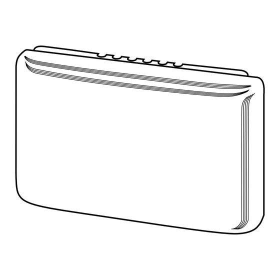
INDOOR REMOTE SENSOR
INDOOR REMOTE SENSOR
INDOOR REMOTE SENSOR
INDOOR REMOTE SENSOR
INDOOR REMOTE SENSOR
NOTE
If in doubt about whether your wiring is millivolt, line, or low
voltage, have it inspected by a qualified heating and air
conditioning contractor or electrician.
Do not exceed the specification ratings.
All wiring must conform to local and national electrical codes
and ordinances.
This control is a precision instrument, and should be handled
carefully. Rough handling or distorting components could cause
the control to malfunction.
The remote sensors cannot be used with systems where power
interruptions are part of normal system operation.
The F145-1328 remote sensor is approved for indoor use
The F145-1328 remote sensor is approved for indoor use
The F145-1328 remote sensor is approved for indoor use
The F145-1328 remote sensor is approved for indoor use
The F145-1328 remote sensor is approved for indoor use
only.
only.
only.
only.
only.
Temperature range:
Temperature range:
Temperature range: 40° to 99°F
Temperature range:
Temperature range:
The F145-1378 remote sensor is approved for outdoor
The F145-1378 remote sensor is approved for outdoor
The F145-1378 remote sensor is approved for outdoor
The F145-1378 remote sensor is approved for outdoor
The F145-1378 remote sensor is approved for outdoor
use only.
use only.
use only.
use only.
use only.
Temperature range of outdoor probe:
Temperature range of outdoor probe:
Temperature range of outdoor probe:
Temperature range of outdoor probe: -40° to 140°F
Temperature range of outdoor probe:
White-Rodgers is a division
of Emerson Electric Co.
www.white-rodgers.com
F145-1328/F145-1378
F145-1328/F145-1378
F145-1328/F145-1378
F145-1328/F145-1378
F145-1328/F145-1378
Indoor Remote Sensor/Outdoor Remote Sensor
INSTALLATION INSTRUCTIONS
INSTALLATION INSTRUCTIONS
INSTALLATION INSTRUCTIONS
INSTALLATION INSTRUCTIONS
INSTALLATION INSTRUCTIONS
OUTDOOR REMOTE SENSOR
OUTDOOR REMOTE SENSOR
OUTDOOR REMOTE SENSOR
OUTDOOR REMOTE SENSOR
OUTDOOR REMOTE SENSOR
Interior Mounting Base
Interior Mounting Base
Interior Mounting Base
Interior Mounting Base
Interior Mounting Base
CAUTION
!
To prevent electrical shock and/or equipment dam-
To prevent electrical shock and/or equipment dam-
To prevent electrical shock and/or equipment dam-
To prevent electrical shock and/or equipment dam-
To prevent electrical shock and/or equipment dam-
age, disconnect electric power to system at main fuse
age, disconnect electric power to system at main fuse
age, disconnect electric power to system at main fuse
age, disconnect electric power to system at main fuse
age, disconnect electric power to system at main fuse
or circuit breaker box until installation is complete.
or circuit breaker box until installation is complete.
or circuit breaker box until installation is complete.
or circuit breaker box until installation is complete.
or circuit breaker box until installation is complete.
WARNING
!
Do not use on circuits exceeding specified voltage.
Do not use on circuits exceeding specified voltage.
Do not use on circuits exceeding specified voltage.
Do not use on circuits exceeding specified voltage.
Do not use on circuits exceeding specified voltage.
Higher voltage will damage control and could cause
Higher voltage will damage control and could cause
Higher voltage will damage control and could cause
Higher voltage will damage control and could cause
Higher voltage will damage control and could cause
shock or fire hazard.
shock or fire hazard.
shock or fire hazard.
shock or fire hazard.
shock or fire hazard.
Do not short out terminals on gas valve or primary
Do not short out terminals on gas valve or primary
Do not short out terminals on gas valve or primary
Do not short out terminals on gas valve or primary
Do not short out terminals on gas valve or primary
control to test. Short or incorrect wiring will damage
control to test. Short or incorrect wiring will damage
control to test. Short or incorrect wiring will damage
control to test. Short or incorrect wiring will damage
control to test. Short or incorrect wiring will damage
thermostat and could cause personal injury and/or
thermostat and could cause personal injury and/or
thermostat and could cause personal injury and/or
thermostat and could cause personal injury and/or
thermostat and could cause personal injury and/or
property damage.
property damage.
property damage.
property damage.
property damage.
Operating humidity range:
Operating humidity range:
Operating humidity range:
Operating humidity range:
Operating humidity range: 0 to 90% RH (non-condensing).
20 gauge, three-conductor shielded cable must be used for all
remote sensor wiring.
20 gauge, three-conductor shielded cable must be used for all
remote sensor wiring.
Outdoor Probe
Outdoor Probe
Outdoor Probe
Outdoor Probe
Outdoor Probe
PRECAUTIONS
PRECAUTIONS
PRECAUTIONS
PRECAUTIONS
PRECAUTIONS
SPECIFICATIONS
SPECIFICATIONS
SPECIFICATIONS
SPECIFICATIONS
SPECIFICATIONS
PART NO. 37-6606A
PART NO. 37-6606A
PART NO. 37-6606A
PART NO. 37-6606A
PART NO. 37-6606A
0440
Advertisement

Related Manuals for White Rodgers F145-1378


Summary of Contents for White Rodgers F145-1378
- Page 1 Temperature range: 40° to 99°F remote sensor wiring. 20 gauge, three-conductor shielded cable must be used for all The F145-1378 remote sensor is approved for outdoor The F145-1378 remote sensor is approved for outdoor The F145-1378 remote sensor is approved for outdoor...
-
Page 2: Outdoor Sensor
"-" or S3 on the shield must be connected to "-" or S3 on the *F145-1049, *F145-1170 THERMOSTAT ONLY. THERMOSTAT ONLY. THERMOSTAT ONLY. THERMOSTAT ONLY. THERMOSTAT ONLY. F145-1328, F145-1378 *Models no longer available Sensor Sensor Sensor Positive Return Signal Negative INDOOR SENSORS INDOOR SENSORS... -
Page 3: Wiring Diagrams
Figure 2 – Staging Thermostat Multi-Stage or Heat Pump Indoor/Outdoor Remote Sensor Wiring Figure 2 – Staging Thermostat Multi-Stage or Heat Pump Indoor/Outdoor Remote Sensor Wiring Figure 2 – Staging Thermostat Multi-Stage or Heat Pump Indoor/Outdoor Remote Sensor Wiring (F145-1328/F145-1378) (F145-1328/F145-1378) (F145-1328/F145-1378) - Page 4 CONFIGURATION CONFIGURATION CONFIGURATION CONFIGURATION CONFIGURATION Comfort-Set II Comfort-Set II Comfort-Set III/Comfort-Set 90/90 Series Comfort-Set III/Comfort-Set 90/90 Series Comfort-Set II Comfort-Set II Comfort-Set II Comfort-Set III/Comfort-Set 90/90 Series Comfort-Set III/Comfort-Set 90/90 Series Comfort-Set III/Comfort-Set 90/90 Series Single Stage Models Single Stage Models Single Stage Models Single Stage Models Single Stage Models: Verify jumper wire W-22...
-
Page 5: Troubleshooting Chart
REMOTE SENSOR TROUBLESHOOTING GUIDE REMOTE SENSOR TROUBLESHOOTING GUIDE REMOTE SENSOR TROUBLESHOOTING GUIDE REMOTE SENSOR TROUBLESHOOTING GUIDE REMOTE SENSOR TROUBLESHOOTING GUIDE Comfort-Set II Comfort-Set II Comfort-Set II Comfort-Set II Comfort-Set II Comfort-Set III/Comfort-Set 90/90 Series Comfort-Set III/Comfort-Set 90/90 Series Comfort-Set III/Comfort-Set 90/90 Series Comfort-Set III/Comfort-Set 90/90 Series Comfort-Set III/Comfort-Set 90/90 Series Single Stage Models... - Page 6 The Emerson logo is a trademark and service mark of Emerson Electric Co.
Need help?
Do you have a question about the F145-1378 and is the answer not in the manual?
Questions and answers