Advertisement
Available languages
Available languages
WHITE-RODGERS
Operator: Save these instructions for future use!
FAILURE TO READ AND FOLLOW ALL INSTRUCTIONS CAREFULLY
BEFORE INSTALLING OR OPERATING THIS CONTROL COULD CAUSE
PERSONAL INJURY AND/OR PROPERTY DAMAGE.
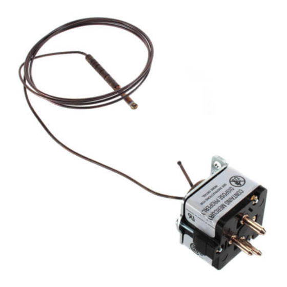
These Mercury Flame Sensors are designed to replace flame
sensors used on automatic pilot ignition systems on original
equipment and retrofit applications. Type 3049 Flame Sensors
are equipped with three quick-connect terminals, while Type
3098 are manufactured with three-prong plugs and designed to
plug into the receptacle on the 36C84 series gas valve. Both
types have SPDT switch mechanisms which are activated by the
heat from the pilot flame.
If in doubt about whether your wiring is millivolt, line, or low
voltage, have it inspected by a qualified heating and air condi-
tioning contractor, electrician, or someone familiar with basic
electricity and wiring.
Do not exceed the specification ratings.
All wiring must conform to local and national electrical codes and
ordinances.
This control is a precision instrument, and should be handled
carefully. Rough handling or distorting components could cause
the control to malfunction.
WARNING
!
Do not use on circuits exceeding specified voltage.
Higher voltage will damage control and could cause
shock or fire hazard.
This product contains mercury. There will not be any exposure to mercury under normal conditions of use. This product may
replace a unit which contains mercury. Do not open mercury cells. If a cell becomes damaged, do not touch any spilled
mercury. Wearing non-absorbent gloves, take up the spilled mercury with sand or other absorbent material and place into a
container which can be sealed. If a cell becomes damaged, the unit should be discarded. Mercury must not be discarded in
household trash. When this unit or the unit it is replacing is to be discarded, place in a suitable container and return to us.
The sensing bulb is for direct flame immersion in the pilot flame.
The top
3
⁄
" should be surrounded by flame.
4
Contact Action: SPDT, snap-action
WHITE-RODGERS DIVISION
EMERSON ELECTRIC CO.
9797 REAVIS RD., ST. LOUIS, MO. 63123
(314) 577-1300, Fax (314) 577-1517
9999 HWY. 48, MARKHAM, ONT. L3P 3J3
(905) 475-4653, FAX (905) 475-4625
3049 and 3098 SERIES
Mercury Flame Sensors
INSTALLATION INSTRUCTIONS
To prevent electrical shock and/or equipment dam-
age, disconnect electric power to system at main fuse
or circuit breaker box until installation is complete.
Shut off main gas to heating system until installation
is complete.
Label all wires prior to disconnection when servicing
controls. Wiring errors can cause improper and dan-
gerous operation.
Following installation or replacement, follow appli-
ance manufacturer's recommended installation and/
or service instructions to insure proper operation.
ATTENTION!
Timing: Contacts close approximately 60 seconds after the pilot
is ignited. Contacts open approximately 40 seconds after the
flame is extinguished.
Printed in U.S.A.
DESCRIPTION
3098 MERCURY
FLAME SENSOR
PRECAUTIONS
CAUTION
!
SPECIFICATIONS
PART NO. 37-3609D
Replaces 37-3609C
9627
Advertisement
Table of Contents

Subscribe to Our Youtube Channel
Summary of Contents for White Rodgers MERCURY FLAME SENSOR 3049
-
Page 1: Installation Instructions
WHITE-RODGERS Operator: Save these instructions for future use! FAILURE TO READ AND FOLLOW ALL INSTRUCTIONS CAREFULLY BEFORE INSTALLING OR OPERATING THIS CONTROL COULD CAUSE PERSONAL INJURY AND/OR PROPERTY DAMAGE. These Mercury Flame Sensors are designed to replace flame sensors used on automatic pilot ignition systems on original equipment and retrofit applications. -
Page 2: Installation
INSTALLATION REMOVING THE OLD FLAME SENSOR The 3049 flame sensors are manufactured with different termi- nal/panel configurations. Some models have three terminals, while others have two ⁄ ” spade terminals and one pin terminal. Figure 5 illustrates the terminal layout and internal switch action for each variation. -
Page 3: Troubleshooting
Once a pilot flame is established, make sure the ignition electrode REMAINS in the pilot flame, and that the flame engulfs at least the top ⁄ ” of the sensing bulb. 10. After approximately 45 seconds, the flame sensor should receive sufficient heat from the pilot flame and switch the main gas valve on. -
Page 4: Spécifications
WHITE-RODGERS Utilisateur: conservez ces instructions pour vous y référer au besoin! SI VOUS NE LISEZ PAS ATTENTIVEMENT CES INSTRUCTIONS AVANT D’INSTALLER ET D’UTILISER LA COMMANDE, VOUS RISQUEZ DE CAUSER DES BLESSURES ET DES DOMMAGES MATÉRIELS. Ces détecteurs de flammes au mercure ont été conçus comme remplacement pour les détecteurs installés sur les allumeurs avec veilleuse automatique de systèmes neufs ou anciens. - Page 5 INSTALLATION DÉMONTAGE DE L’ANCIEN DÉTECTEUR DE FLAMME Les détecteur de flamme 3049 sont fabriqués avec un certain nombre de configurations des bornes et des panneaux. Certains modèles sont dotés de trois cosses de de deux cosses de ⁄ ” et d’une borne à broche. La figure 5 illustre la disposition des bornes et la commutation qui corre- spond à...
-
Page 6: Dépannage
Avec les détecteurs 3098 enfichables, installez le commutateur en insérant le détecteur de flamme dans la prise correspondante du robinet à gaz. Avec les détecteurs 3049, installez le commutateur en raccordant les fils sur les bornes correspondantes. Mettez le système sous tension et observez le brûleur de veilleuse ainsi que l’électrode d’allumage.


Need help?
Do you have a question about the MERCURY FLAME SENSOR 3049 and is the answer not in the manual?
Questions and answers