Table of Contents
Advertisement
Quick Links
Download this manual
See also:
Instruction Manual
Advertisement
Table of Contents

Summary of Contents for Campbell SC932A
- Page 1 SC932A 9-Pin to RS-232-DCE Interface Revision: 2/04 C o p y r i g h t ( c ) 1 9 8 7 - 2 0 0 4 C a m p b e l l S c i e n t i f i c ,...
- Page 2 Warranty and Assistance The SC932A 9-PIN TO RS-232-DCE INTERFACE is warranted by CAMPBELL SCIENTIFIC, INC. to be free from defects in materials and workmanship under normal use and service for twelve (12) months from date of shipment unless specified otherwise. Batteries have no warranty. CAMPBELL SCIENTIFIC, INC.'s obligation under this warranty is limited to repairing or...
-
Page 3: Table Of Contents
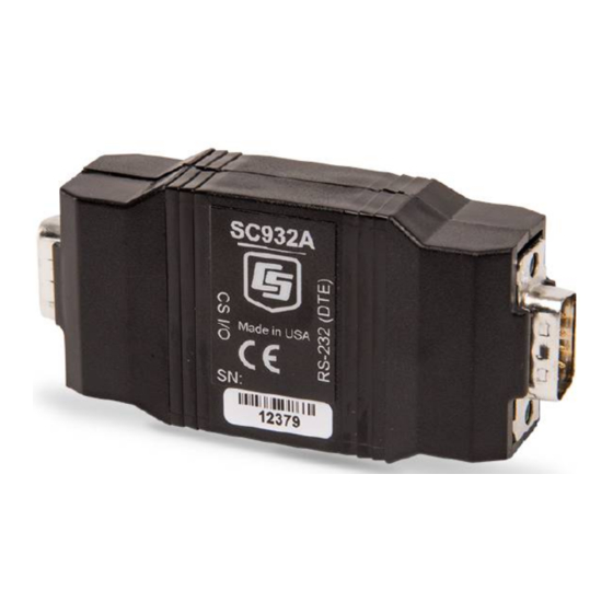
4.1 RAD Modem - Two Way................4 4.2 RAD Modem Wiring and Grounding............4 4.3 Testing RAD Modem Communication .............6 Figures 1. SC932A 9-Pin to RS-232-DCE Interface............1 2. Two Way Communication ................4 3. Installation of Spark Gap Protection............5 Table 1. Approximate Range, miles and km .............4... - Page 4 This is a blank page.
-
Page 5: General Description
• True RS-232 signal levels. • Power for the SC932A is supplied from the 5 V supply on pin 1 of the datalogger’s I/O port. The SC932A will use the 5 V supply to power the RS-232 modem if needed. -
Page 6: Specifications
Ground RING Ring signal to datalogger SC932A transmits on this line Modem Enable—must be high for transfer Synchronous Device Enable—data blocked when high SC932A receives on this line Data Rates The SC932A will support baud rates up to 115,200 bps. -
Page 7: Installation
SC932A 9-Pin to RS-232-DCE Interface Electrical The SC932A uses power from the +5 V line on the 9-pin interface connected to the datalogger. Additional current (up to 10 mA) from the 5 V supply may be used by the RS- 232 device connected to the SC932A. -
Page 8: Rad Modem - Two Way
Figure 3 shows a typical setup of the RAD modems. Installation is as follows: Set the DCE/DTE switch on the back of the RAD modem connected to the SC932A to DCE. For a RAD modem connected to a PC, set the DCE/DTE switch to DCE. For a RAD modem connected to a serial printer, set the DCE/DTE switch to DTE. -
Page 9: Installation Of Spark Gap Protection
SC932A 9-Pin to RS-232-DCE Interface 6361 includes hardware for mounting to ground lug of CSI enclosures models ENC 10/12, ENC 12/14, or ENC 16/18). Spark gap wiring is straight through such that pin to pin continuity exists between the two modems. -
Page 10: Testing Rad Modem Communication
RAD modem powered by the SC932A. RAD does sell a 9 volt power supply that will boost the signals enough to meet some of these more demanding applications. Please contact RAD for more information. - Page 11 To verify that the datalogger and its serial I/O port are working, try to access input memory locations using a laptop PC with the SC32B or the CR10KD Keyboard Display. If the datalogger passes tests 4, 5, and 6, then the SC932A is suspect and will need to be repaired or replaced.
- Page 12 SC932A 9-Pin to RS-232-DCE Interface This is a blank page.
- Page 13 This is a blank page.
- Page 14 Campbell Scientific Companies Campbell Scientific, Inc. (CSI) 815 West 1800 North Logan, Utah 84321 UNITED STATES www.campbellsci.com info@campbellsci.com Campbell Scientific Africa Pty. Ltd. (CSAf) PO Box 2450 Somerset West 7129 SOUTH AFRICA www.csafrica.co.za sales@csafrica.co.za Campbell Scientific Australia Pty. Ltd. (CSA)


Need help?
Do you have a question about the SC932A and is the answer not in the manual?
Questions and answers