Advertisement
Advertisement
Table of Contents

Subscribe to Our Youtube Channel
Related Manuals for Bose ControlSpace CC-16


Summary of Contents for Bose ControlSpace CC-16
- Page 1 ® ControlSpace CC-16 Zone Controller Safety Instructions & Install Guide...
-
Page 2: Important Safety Instructions
11. See product enclosure for safety related markings. 12. Only use attachments/accessories specified by the manufacturer. ©2005 Bose Corporation. No part of this work may be reproduced, modified, distributed or otherwise used without prior written permission. - Page 3 Important Safety Instructions Information about products that generate electrical noise This equipment has been tested and found to comply with the limits for a Class B digital device, pursuant to Part 15 of the FCC rules. These limits are designed to provide reasonable protec- tion against harmful interference in a residential installation.
-
Page 4: Regulatory Information
Important Safety Instructions Caution ® Check local regulations before installing the ControlSpace CC-16 zone controller. The building code may require professional installation by a skilled technician or licensed contractor. Regional electrical codes may require similar qualifications for wiring the system. This product must be used with a Class 2 power supply. -
Page 5: Features And Functions
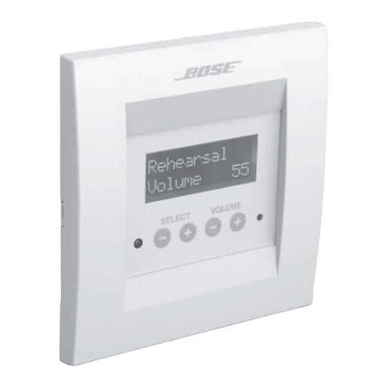
Introduction ® ® The Bose ControlSpace CC-16 zone controller is an elegant wall-mounted device designed to provide end-user control of ControlSpace systems. Custom programming allows the CC-16 to control a variety of the system elements, from switching audio sources to selecting “scenes”... -
Page 6: Quick Start
Introduction Quick start 1. Run power and network (2-wire) cables from the ESP-88 to the CC-16 mounting location and install a mounting box. 2. Set the DIP switches to define the unit address and termination (see silkscreen on back of CC-16). -
Page 7: Installation
Installation Cabling The CC-16 zone controller requires power and network cables. In some cases, these can be supplied over the same multi-conductor cable. When multiple CC-16s are used, run the network (and optionally the power cable) from the ESP-88 to each zone controller in a daisy chain. -
Page 8: Maximum Cable Distances
Installation Maximum cable distances Number of CC-16s Wire Gauge/ Power Supply Voltage 24 AWG 18V 2000 ft (610 m) 1852 ft (564 m) 926 ft (282 m) 247 ft (75 m) 24 AWG 12V 1481 ft (451 m) 741 ft (226 m) 370 ft (113 m) 99 ft (30 m) 24 AWG 9V... -
Page 9: Dip Switch Settings
DIP Switch Settings The CC-16 zone controller has an 8-position DIP switch located on the back of the unit. The DIP switches control addressing and termination settings. DIP switch addresses Up to fifteen CC-16s can be connected to an ESP-88 and each must have a unique address. - Page 10 DIP Switch Settings Termination The CC-16 zone controller uses a 2-wire RS-485 network to communicate with the ESP-88 sound processor. For optimum performance, the RS-485 network must be “terminated.” The CC-16 includes built-in termination resistors which make it easy to terminate the network. Termination is accomplished by setting DIP switches 1 and 2 to the ON position.
-
Page 11: Connecting The Wires
Wiring Connecting the wires The CC-16 zone controller uses a standard 6-wire Eurostyle terminal block for power and network connections. 1. Connect the network cable to the RS-485 A/B pins on the ESP-88. Note which wire is connected to A and B. 2. -
Page 12: Power Supply
Wiring Power supply The CC-16 zone controller requires a minimum of 100mA at 8VDC. For convenience and consistency, we recommend you place the power supply in an equipment area adjacent to the network connection. Power can be supplied over the network cable, from a power supply local to the unit, or from a remotely-located power supply with a separate cable run. - Page 13 Mounting Mounting the CC-16 zone controller Warning: The CC-16 must be installed in a National Electric Code (NEC) approved, enclosed electrical wall box. After setting the DIP switches and connecting the wires, mount the CC-16 zone controller in the electrical box. Two sets of screws are provided. Use the screws that are appropriate for your wall-box –...
-
Page 14: Troubleshooting
Troubleshooting • Ensure that the power supply is wired correctly and plugged in No power • Try disconnecting other CC-16s if sharing a supply • Verify that the supply is DC and provides a minimum 100mA at 8V • Press a button to see if backlight comes on (the backlight turns off Screen is blank after a period of inactivity) •... -
Page 15: Specifications
Specifications Input voltage 8 - 18VDC, 100mA Max network cable length 2000 feet (609m) Number of CC-16 zone controllers per ESP-88 Sound Processor Dimensions... -
Page 16: Warranty
We will repair or replace any defective parts within a reasonable period of time and free of charge. How you can obtain warranty service: 1. You can ship the system to either a Bose Service Agency or to Bose directly with a proof of purchase from an authorized dealer.Please: A. - Page 17 ORIGINAL PROOF OF PURCHASE FROM AN AUTHORIZED BOSE DEALER. THE MAXIMUM LIABILITY OF BOSE SHALL NOT EXCEED THE ACTUAL PURCHASE PRICE PAID BY YOU FOR THE PRODUCT. IN NO EVENT SHALL BOSE BE LIABLE FOR SPECIAL, INCIDENTAL, CONSEQUENTIAL OR INDIRECT DAMAGES. SOME PLACES DO NOT ALLOW...
- Page 20 ©2007 Bose Corporation, The Mountain, Framingham, MA 01701-9168 USA 285042 AM Rev.01...
Need help?
Do you have a question about the ControlSpace CC-16 and is the answer not in the manual?
Questions and answers