
Related Manuals for Friedrich SV08A10


Summary of Contents for Friedrich SV08A10
-
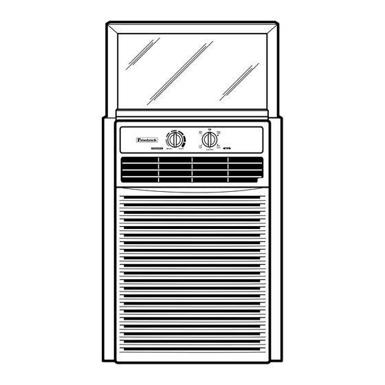
Page 1: Slider Casement
Room Air Conditioner Service and Parts Slider Casement 115Volts • SV08A10 • SV10A10 • SV12A10 SV08 / SV10 / SV12 (01/03) Manual High Cool Cool Temperature Mode Warmer Cooler Low Cool... -
Page 2: Table Of Contents
SERVICE MANUAL This parts etc. This room air conditioner was manufactured and assembled under a strict quality control system. The refrigerant is charged at the factory. Be sure to read the safety precautions prior to servicing the unit. 1.1 SAFETY PRECAUTIONS 1. -
Page 3: Specifications
1.3 SPECIFICATIONS 1.3.1 FOR SV08A10 / SV10A10 / SV12A10 MODELS ITEMS POWER SUPPLY COOLING CAPACITY INPUT RUNNING CURRENT (BTU/W . h) E.E.R OPERATING INDOOR (°C) CONDITION OUTDOOR (°C) REFRIGERANT (R-22) CHARGE EVAPORATOR CONDENSER FAN, INDOOR FAN, OUTDOOR FAN SPEEDS, FAN/COOLING... -
Page 4: Features
The temperature is selected by moving the knob to the desired position. • MODE - Turns air conditioner off. - Med speed fan operation without cooling. - Low speed fan operation without cooling. - Cooling with high speed fan operation. -
Page 5: Disassembly Instructions
2. DISASSEMBLY INSTRUCTIONS — Before the following disassembly, set POWER SWITCH to OFF and disconnect the power cord. 2.1 MECHANICAL PARTS 2.1.1 FRONT GRILLE 1. Open the inlet grille downward and remove the air filter. 2. Remove the screws which fasten the front grille.(See Figure 1) 3. -
Page 6: Air Handling Parts
2.2 AIR HANDLING PARTS 2.2.1 AIR GUIDE AND TURBO FAN 1. Remove the front grille. (Refer to section 2.1.1) 2. Remove the cabinet. (Refer to section 2.1.2) 3. Remove the control box. (Refer to section 2.1.3) 4. Remove the 4 screws which fasten the brace. 5. -
Page 7: Shroud
2.2.3 SHROUD 1. Remove the fan. (Refer to section 2.2.2) 2. Remove the shroud. (See Figure 8) 3. Re-install the components by referring to the removal procedure, above. 2.3 ELECTRICAL PARTS 2.3.1 OVERLOAD PROTECTOR 1. Remove the cabinet. (Refer to section 2.1.2) 2. -
Page 8: Capacitor
2.3.3 CAPACITOR 1. Remove the cabinet. (Refer to section 2.1.2) 2. Remove the screw and the clamp which fastens the capacitor. 3. Disconnect all the leads of capacitor terminals. 4. Re-install the components by referring to the removal procedure, above. (See Figure 11) 2.3.4 POWER CORD 1. -
Page 9: Motor
2.3.7 MOTOR 1. Remove the cabinet. (Refer to section 2.1.2) 2. Remove the turbo fan. (Refer to section 2.2.1) 3. Remove the fan. (Refer to section 2.2.2) 4. Remove the 4 screws which fasten the motor from the Motor Mount. (See Figure 15) 5. -
Page 10: Capillary Tube
2.4.3 CAPILLARY TUBE 1. Remove the cabinet. (Refer to section 2.1.2) 2. After discharging the refrigerant completely, unbraze the interconnecting tube at the capillary tube.(See caution above) NOTES — Replacement of the refrigerant. 1. When replacing the refrigerant, be sure to Discharge the refrigerant system using a Freon recovery System. - Page 11 Equipment needed: Vacuum pump, Charging cylinder, Manifold gauge, Brazing equipment. Pin-off tool capable of making a vapor-proof seal, Leak detector, Tubing cutter, Hand Tools to remove components, Service valve. Figure 18B-Charging Figure 18A-Pulling Vacuum —11—...
-
Page 12: Installation
On exceptionally hot and humid days the air conditioner may overflow condensed water. If the air conditioner is used in hot and a high humidity zone, exchange the DRAIN PIPE.(See Figure 20, Figure 21) Cooled air... -
Page 13: Window Requirements
Support Bracket Bolt (2) Nut (2) For installation in a casement window, the window frame assembly and the side of the building must be adequate to support the weight of the air conditioner. Side Guide Upper Guide Leveling Side Guide bolt &... -
Page 14: Horizontal Sliding Window Installation
The air conditioner is designed to operate with the bottom of the base pan approximately half-full of water. 5. Fasten side guides to the sides of the air conditioner using 3-type A screws per guide. start with first screw at middle of guide. (See Figure 25) 6. -
Page 15: Casement Window Installation
Pinch off excess length so seal is even with the bottom of side guide. (See Figure 28) 10. Place air conditioner in window opening. It should sit on bracket assembly so that curtain frame and cabinet side guides are against top and side window jambs. -
Page 16: Outside Dimensions
4. TROUBLESHOOTING GUIDE 4.1 OUTSIDE DIMENSIONS 607(23 4.2 PIPING SYSTEM CAPILLARY TUBE COMPRESSOR TURBO FAN EVAPORATOR COIL Following is a brief description of the important components and their functions in the refrigeration system. Refer to Fig. 31 to follow the refrigeration cycle and the flow of the refrigerant in the cooling cycle. EVAPORATOR COILS COOLED LIQUID... -
Page 17: Troubleshooting Guide
4.3 TROUBLESHOOTING GUIDE In general, possible trouble is classified in two kinds. The one is called Starting Failure which is caused from an electrical defect, and the other is ineffective Air Conditioning caused by a defect in the refrigeration circuit and improper application. Unit runs but poor cooling. - Page 18 Check of power source. Check of control switch setting. Compressor only fails to start. Drop of power voltage. Defect of compressor capacitor. Capacitor check. Replacement Irregular motor resistance ( Irregular motor insulation ( Replacement of compressor (Motor damaged) Fails to Start Improper thermostat setting.
-
Page 19: Room Air Conditioner Voltage Limits
ROOM AIR CONDITIONER VOLTAGE LIMITS NAME PLATE RATING 115V ±10% COMPLAINT Fan motor will not run. No power Power supply cord Rotary switch Wire disconnected or connection loose Capacitor (Discharge capacitor before testing.) Will not rotate Revolves on overload. Fan motor runs intermittently Fan motor noise. - Page 20 COMPLAINT Compressor will not run, Thermostat but fan motor runs. Capacitor (Discharge capacitor before servicing.) Compressor Overload Compressor cycles on Voltage overload. Overload Fan motor Compressor cycles on overload. Condenser air flow restriction Condenser fins (damaged) Capacitor Compressor cycles on overload.
-
Page 21: Schematic Diagram
5. SCHEMATIC DIAGRAM 5.1 CIRCUIT DIAGRAM MODEL : SV10A10 / SV12A10 LOCATION DESCRIPTION POWER CORD ROTARY SWITCH FAN MOTOR CAPACITOR THERMOSTAT COMPRESSOR PART NO. SV10A10 6411A20011N 2H00598E 4681A20069C 6120AR2194P 2H01109Q 2520UKAC2GA —21— S: Service Parts N: Non Service Parts Q'TY PER SET SV12A10 6411A20011P... -
Page 22: Circuit Diagram
5.2 CIRCUIT DIAGRAM MODEL : SV08A10 LOCATION DESCRIPTION POWER CORD ROTARY SWITCH FAN MOTOR CAPACITOR THERMOSTAT COMPRESSOR PART NO. SV08A10 6411A20011L 2H00598E 4681A20069A 6120AR2359H 2H01109M 2520UAGC2AA —22— S: Service Parts N: Non Service Parts Q'TY MARKS PER SET... -
Page 23: Exploded View
6. EXPLODED VIEW 130910 249950 269310 266003 W0CZZ M ed O ff C oo le r H ig C oo C oo M ed C oo M od 264110 149410 135312 152312 147582-1 145200 147582-2 147581 135301 135303 148000 352390 349001 346811 349600... -
Page 24: Replacement Parts List
7. REPLACEMENT PARTS LIST MODEL : SV08A10, SV10A10, SV12A10 LOCATION DESCRIPTION 130410 BASE ASSY, SINGLE 130910 CABINET ASSY, SINGLE 135303 GRILLE INLET 135312 GRILLE ASSY, FRONT 147581 VANE, HORIZONTAL 147582 VANE, VERTICAL 148000 BRACE 149410 KNOB ASSY 149980 SHROUD ASSY... - Page 25 MEMO —25—...
- Page 26 MEMO —26—...
- Page 27 Use Factory Certified Parts... FRIEDRICH AIR CONDITIONING CO. Visit our web site at www.friedrich.com Post Office Box 1540 • 4200 N. Pan Am Expressway • San Antonio, Texas 78295-1540 • (210) 357-4400 • FAX (210) 357-4480 P/NO.: 3828A20190G Printed in the U.S.A...
Need help?
Do you have a question about the SV08A10 and is the answer not in the manual?
Questions and answers