
Subscribe to Our Youtube Channel
Related Manuals for Axminster AWC20HP


Summary of Contents for Axminster AWC20HP
-
Page 1: Air Compressor
AWC20HP Air Compressor Axminster Tool Centre, Unit 10 Weycroft Avenue, Axminster, Devon EX13 5PH axminster.co.uk... -
Page 2: Table Of Contents
Index of Contents Page No Index of Contents......................................02 Declaration of Conformity..................................... 02 What’s Included......................................... 03 Safety Precautions......................................03 Specifications (AWC20HP Air Compressor)............................. 04 Assembly Instructions....................................04-05 Illustration and Parts Description of Air Compressor......................05-06-07 Operating Instructions....................................08 Maintenance........................................09 Parts Breakdown....................................... 10 Parts List.......................................... -
Page 3: What's Included
10. Do not adjust the tank pressure switch without 2. Never leave inflammable objects or materials near reference to Axminster Power Tool Service to the compressor. Department. 3. Always check oil level before using the 11. -
Page 4: Specifications (Awc20Hp Air Compressor)
Report any problems to and fill with good quality compressor oil, (see our Axminster Power Tool Centre’s Customer Services catalogue) until the level is in line with the circle Department. Fit the wheels, (see instructions below). -
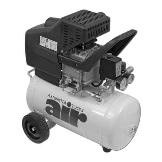
Page 5: Illustration And Parts Description Of Air Compressor
Assembly Instructions Fitting the quick release coupling Wrap some PTFE tape (A) around the thread on the 1/4" BSP male coupling (B) and screw it into the pressure regulator outlet, lightly tighten using a spanner. (DO NOT OVERTIGHTEN) The compressor is now ready for use. Illustration and Parts Description of Air Compressor Oil drain plug Oil level indicator... - Page 6 Illustration and Parts Description of Air Compressor Fig 1 Air inlet filter Motor cover Cylinder Handle On/Off switch Pressure switch 1/4" BSP male coupling Outlet pressure Handle gauge Crankcase Tank pressure gauge Oil drain plug Pressure relief valve Wheel Crankcase Tank Check valve Front foot...
- Page 7 Illustration and Parts Description of Air Compressor Oil filler plug Filter On/Off switch Pressure adjuster Fig 2 Water drain valve...
-
Page 8: Operating Instructions
Operating Instructions The outlet air pressure can be regulated by rotating the drops below a pre-set level. The cut-in and cut-out regulator knob clockwise to increase the pressure and pressures are factory set and should not need to be anticlockwise to reduce it. Do not leave the regulator altered. -
Page 9: Maintenance
Maintenance Daily: filler plug, place a suitable container under the drain plug and drain the oil right out. (See fig 8) Replace drain Drain water from tank. (See fig 5) plug and refill to the level mark on the sight glass. Weekly: Yearly: Check oil level and top-up if necessary. -
Page 10: Parts Breakdown
Parts Breakdown... -
Page 11: Parts List
Parts List... -
Page 12: Trouble Shooting
Carefully clean all sealing surfaces before re-assembling The compressor Crank bearing failure Stop the compressor and contact Axminster does not reach the Tool Centre set pressure and overheats The compressor is Pressure switch failure Stop the compressor quickly.
Need help?
Do you have a question about the AWC20HP and is the answer not in the manual?
Questions and answers