Avocent ESP-4 MI Installer/User Manual
Serial hub
Hide thumbs
Also See for ESP-4 MI:
- Technical specifications (2 pages) ,
- Installer/user manual (96 pages)
Table of Contents
Advertisement
Advertisement
Table of Contents

Related Manuals for Avocent ESP-4 MI


Summary of Contents for Avocent ESP-4 MI
- Page 1 ESP-4 MI Serial Hub Installer/User Guide...
- Page 2 INSTRUCTIONS This symbol is intended to alert the user to the presence of important operating and maintenance (servicing) instructions in the literature accompanying the appliance. DANGEROUS VOLTAGE This symbol is intended to alert the user to the presence of uninsulated dangerous voltage within the product’s enclosure that may be of sufficient magnitude to constitute a risk of electric shock to persons.
- Page 3 ESP-4 MI Serial Hub Installer/User Guide Avocent, the Avocent logo and The Power of Being There are registered trademarks of Avocent Corporation or its affiliates. All other marks are the property of their respective owners. © 2005 Avocent Corporation. All rights reserved. 590-524-501A...
- Page 4 USA Notification WARNING: Changes or modifications to this unit not expressly approved by the party responsible for compli- ance could void the user’s authority to operate the equipment. NOTE: This equipment has been tested and found to comply with the limits for a Class A digital device, pur- suant to Part 15 of the FCC rules.
-
Page 5: Table Of Contents
List of Tables ........................vii Chapter 1: Introduction ....................1 Features ............................. 1 Chapter 2: Hardware Installation and Network Configuration........3 ESP-4 MI Hub Kit Contents....................... 3 Hardware Overview........................... 3 Physical interfaces........................4 Network interface........................4 Pin Assignments ..........................5 Serial ports .......................... - Page 6 ESP-4 MI Serial Hub Installer/User Guide Configurable Features ........................23 Chapter 4: Web Interface....................25 Accessing the Web Interface ......................25 Passwords ............................26 Displaying or Changing Network Configuration Values ..............26 Displaying or Changing Serial Port Interface, Attributes and Connection Methods ..... 27 Sending a Break to a Port........................
- Page 7 Table of Contents Displaying General Statistics ......................42 Displaying Port Statistics ........................ 42 Displaying Connection Status......................43 Displaying and Using Debug Features ................... 43 Chapter 6: Configuration Files..................45 Sample Configuration File....................... 45 File Format and Command Syntax ....................46 Port Interface Command .........................
- Page 8 ESP-4 MI Serial Hub Installer/User Guide...
-
Page 9: List Of Tables
Table 4.4: Serial Port Active Connection Status Display..............32 Table 4.5: Serial Port Redirection Connections Status Display ............. 33 Table 5.1: Reference to Connection Method Rules and Values ............39 Table 6.1: Configurable Features Commands ................49 Table A.1: ESP-4 MI Serial Hub Technical Specifications ............. 51... - Page 10 ESP-4 MI Serial Hub Installer/User Guide Table B.1: ESP-View Utility Datascope Window Buttons............... 53 Table B.2: ESP-View Utility Status Display ..................56 Table C.1: ESP-Install Program Commands .................. 61...
-
Page 11: Chapter 1: Introduction
Modular adaptors are available to facilitate the connection between the ESP-4 MI serial hub and the target devices. The ESP-4 MI hub uses an external power supply, which is provided with the hub. See Electrical on page 8 for more information. - Page 12 ESP Ethernet serial hubs without need for on-site technical personnel. See ESP-Install Program on page 58. Management tools You may configure and/or manage the ESP-4 MI serial hub using the following tools: • Web interface - see Chapter 4, beginning on page 25 •...
-
Page 13: Chapter 2: Hardware Installation And Network Configuration
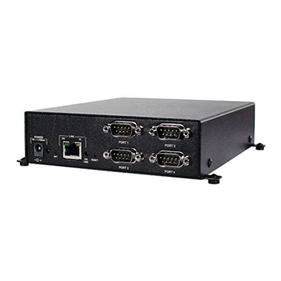
Technical Support for details. Hardware Overview All connectors, LEDs and buttons are on the front of the ESP-4 MI serial hub. The lower left corner of the front panel contains the electrical connector. For more information, see Electrical on page 8. -
Page 14: Physical Interfaces
This termination should always be set when the unit is configured for RS-422, as this is a point-to-point configuration. If your configuration includes supplying your own external termination, the termination on the ESP-4 MI hub should not be used. Network interface The network interface speed may be configured with the following values. -
Page 15: Pin Assignments
10 Mb/second, full duplex 10 Mb/second, half duplex Pin Assignments This section lists the pin assignments for the serial ports, available adaptors and the ESP-4 MI serial hub Ethernet connector. Serial ports Table 2.2 lists the pin assignments for the RS-232 interface. This information is also provided on a label on the bottom of the hub. -
Page 16: Adaptors
RS-485. Pins 7 and 8 should be left open for an RS-422 configuration. Adaptors Two adaptors are available from Avocent to enable use of standard CAT 5 cable twisted pairs for RS-422 receive and transmit signals, plus one of the pairs for the RS-485 signal pair. -
Page 17: Ethernet Connector
Chapter 2: Hardware Installation and Network Configuration Table 2.5 lists the pin assignments for the RS-485 CAT 5 adaptor. Table 2.5: RS-485 CAT 5 Adaptor Pin Assignments Pin Number - DB-9 RS-422 Description Pin Number - RJ-45 RxD (+) Receive Data (pos) RxD (-) Receive Data (neg) TxD (+) -
Page 18: Electrical
European CE Immunity Standards. Installing the Hub The ESP-4 MI hub ships ready to use in a tabletop environment, with four rubber feet on the bottom of the hub. NOTE: The power outlet should be near the equipment and be easily accessible. -
Page 19: After Startup And Address Configuration
BootP or DHCP server. • After the ESP-4 MI hub acquires an IP address (by any method), it will no longer use BootP or DHCP. Therefore, you cannot change the network values using this method. •... -
Page 20: Reinitializing And Resetting The Hub
ESP-4 MI Serial Hub Installer/User Guide Table 2.7 indicates when each type of change takes effect. Table 2.7: When Changes Take Effect On next Action Immediately After reboot connection Network address changes (IP, gateway, subnet) Network interface speed Enabling/disabling the hub’s configurable features Changing a port’s physical interface... -
Page 21: Chapter 3: Connection Methods, Attributes And Configurable Features
Modem emulation - see page 16 • Configuration utility - see page 22 Each connection method may be enabled or disabled for each ESP-4 MI port. A port may have multiple connection methods enabled, with the following exceptions. • The raw TCP client connection method is exclusive; when it is enabled on a port, no other con- nection methods can be enabled for that port. -
Page 22: Serial Port Redirection
Telnet server The Telnet server connection method allows a user to make a Telnet connection to a serial port on the ESP-4 MI hub and then transmit/receive data using the standard Telnet protocol. This method is also known as reverse Telnet. -
Page 23: Raw Tcp Server
The raw TCP server connection method allows a remote client to make a TCP socket connection to a serial port on the ESP-4 MI hub and then transmit/receive data using standard TCP. The remote client initiates the TCP session, using a predefined IP port number. -
Page 24: Raw Tcp Client
The default value is disabled. Raw TCP client The raw TCP client connection method allows the ESP-4 MI hub to make a TCP-based connection to a remote server and then transmit/receive data using standard TCP. The client hub initiates the TCP session. -
Page 25: Table 3.4: Raw Tcp Client Connection Method Configurable Items
Only a single destination address can be configured for each serial port. The address address cannot be 0.0.x.x, 127.x.x.x, 192.1.1.1, 248-255.x.x.x or the IP address of the ESP-4 MI hub. Destination IP Specifies the IP port number on which the remote server is listening. Valid values are 0-65535. -
Page 26: Modem Emulation
(Used only when Allow Outgoing Calls is enabled.) Specifies the IP address to be used when Destination IP an ATDT modem command is entered without an IP address. The address cannot be 0.0.x.x, Address 127.x.x.x, 248-255.x.x.x or the IP address of the ESP-4 MI hub. - Page 27 Chapter 3: Connection Methods, Attributes and Configurable Features Table 3.5: Modem Emulation Connection Method Configurable Items (Continued) Item Description (Used only when Allow Outgoing Calls is enabled.) Specifies the IP port number to be used Destination IP when an ATDT modem command is entered without an IP port. Valid values are 1024-65535. Port The default value is 5001 for port 1, 5002 for port 2, 5003 for port 3 and 5004 for port 4.
-
Page 28: Table 3.6: Modem Commands
(No Carrier or 3), depending on the ATV value. Returns the ESP-4 MI hub to data mode. When the hub returns to data mode, it once again listens for incoming data from the ESP-4 MI hub at the other end of the connection. The... - Page 29 V1 and E0 will be accepted; &W1 will be discarded. Command mode When an ESP-4 MI serial port is configured for the modem emulation connection method but no TCP connection is established, the port is in command mode. When an ATDT command is received and a session is established, the port is in data mode.
-
Page 30: Table 3.7: Modem Command Response Codes
The remote hub will obviously not be receiving any data from the TCP connection, but if it receives serial data from its attached device, it will attempt to send it to the ESP-4 MI hub that is not listening because it is in command mode. In this case, the data will be buffered until the port on the intended recipient ESP-4 MI hub returns to data mode. -
Page 31: Table 3.8: Dialout Translation Set
In all cases, when a TCP connection is active, the ESP-4 MI hub will raise the outbound DTR signal to indicate that the connection is valid (which should be seen as inbound DCD by the serial device, which is usually a PC when modem emulation is used). -
Page 32: Configuration Utility
The connection will be closed if the inbound control signal changes from logically high to low. When a TCP connection is active, the ESP-4 MI hub will raise the outbound DTR signal to indicate that the connection is valid (which should be seen as inbound DCD by the serial device). If the remote end breaks the TCP connection, DTR will be lowered to indicate a Carrier Drop to the attached serial device. -
Page 33: Configurable Features
(espcfg or NT driver coinstaller). The default value is enabled. When enabled, the SNMP interface is used for monitoring and limited Allow administrative configuration of the ESP-4 MI hub. When disabled, tools such as espdiag will not functions via SNMP work. The default value is enabled. - Page 34 Configuration utility - see Displaying or Changing Configurable Features on page 41 • Configuration file - see Configurable Features Commands on page 49 When the ESP-4 MI serial hub is reinitialized, all configurable features are restored to their default setting (enabled).
-
Page 35: Chapter 4: Web Interface
The web interface may be accessed using any standard web browser with the IP address of the hub as the URL. For example, if an ESP-4 MI serial hub has an IP address of 192.168.0.5, entering the will connect to the web interface. -
Page 36: Passwords
The web interface requires an administration password for access. When the hub ships (or after it is reinitialized), there is no configured password. When you access the ESP-4 MI serial hub, you are prompted for a username and password. The username field is ignored. If a password has not yet been set, any alphanumeric password will be accepted. -
Page 37: Displaying Or Changing Serial Port Interface, Attributes And Connection Methods
If you changed any values, click Apply. If you changed the address information, it will not take effect until the next reboot of the ESP-4 MI hub. To reboot, click the Reboot button. If the IP address had not been previously set or the hub has been reinitialized, the hub reboots automatically. -
Page 38: Sending A Break To A Port
ESP-4 MI Serial Hub Installer/User Guide To change a field, click the appropriate radio button, enter a valid value or choose from a listbox. Table 4.1 indicates where to find more information. Table 4.1: Reference to Connection Method Rules and Values... -
Page 39: Displaying Or Updating Flash Memory
Chapter 4: Web Interface • Amount of SDRAM in megabytes • Amount of Flash memory in megabytes • Amount of EEPROM configuration memory in kilobytes • Hub MAC address • Hub serial number This information cannot be modified. To display hardware information: Select Hardware Information from the Main Menu. -
Page 40: Displaying Or Changing Configurable Features
If you changed any setting, click Apply. The change will not take effect until the next reboot. To reboot, click the Reboot button. When the ESP-4 MI serial hub is reinitialized, all configurable features are restored to their default settings. -
Page 41: Displaying General Statistics
Displaying Port Statistics The Port Statistics display includes the information described in Table 4.3 for each port. All values are cumulative since the ESP-4 MI serial hub was last reset. This display refreshes every five seconds. Table 4.3: Port Statistics Display... -
Page 42: Displaying Connection Status
ESP-4 MI Serial Hub Installer/User Guide Table 4.3: Port Statistics Display (Continued) Item Description Baud rate, data size (5-8 bits), parity (N=none, O=odd, E=even, M=mark or Baudrate/Sz/Par/Stp S=space) and number of stop bits (1 or 2). Frame/Parity/Overrun Number of framing errors, parity errors and overruns. -
Page 43: Rebooting The Hub
The Port Redirection Connections section includes the information described in Table 4.5 about the servers that are connected to each of the ESP-4 MI serial ports. This display is meaningful only when a serial port is being accessed using the serial redirection connection method. -
Page 44: Reinitializing The Hub
ESP-4 MI Serial Hub Installer/User Guide You may also reboot the hub using the configuration utility (see Rebooting the Hub on page 42) or the RESET button on the front panel (see Resetting on page 10). Reinitializing the Hub The Initialize operation resets all configurable values to their factory defaults, including the IP address and password. -
Page 45: Chapter 5: Configuration Utility
Accessing with Telnet You may initiate a Telnet session to the IP address of the ESP-4 MI serial hub and the standard Telnet port 23. For example, if a hub has an IP address of 192.168.0.5, entering telnet 192.168.0.5... -
Page 46: Accessing A Hub With No Configured Ip Address
IP address to be configured using DHCP/BootP. The port will be configured at 19,200 baud, 8 bits per character, no parity, 1 stop bit and no flow control. If the ESP-4 MI serial hub already has an IP address or if the address is acquired through DHCP/BootP, this access method will not be active. -
Page 47: Passwords
No encryption is used when entering the password with the configuration utility. If you reinitialize the ESP-4 MI serial hub, the password is lost; you will be required to create a password the next time you access the configuration utility or the web interface. -
Page 48: Displaying Or Changing Port Interface, Attributes And Connection Methods
If you changed the address information, it will not take effect until the ESP-4 MI hub is rebooted (see Rebooting the Hub on page 42). If the IP address had not been previously set or the hub has been reinitialized, the hub reboots automatically. -
Page 49: Sending A Break To A Port
Chapter 5: Configuration Utility You are prompted to modify the connection values. Enter for yes or for no. If you choose to modify the connection values, the utility will prompt for all connection parameters. The utility will prompt to enable each connection method, regardless of whether the method is currently enabled. -
Page 50: Displaying Hardware Information
ESP-4 MI Serial Hub Installer/User Guide To send a break to a port: From the Top Menu, enter the number (1-4) corresponding to the desired port. The Port Configuration menu for that port appears. Enter from the Port Configuration Menu. -
Page 51: Displaying Or Changing Configurable Features
If you enter , SNMP will remain enabled; if you enter , SNMP will be disabled. When the ESP-4 MI serial hub is reinitialized, all configurable features are restored to their default settings. Downloading a Configuration File To ease the task of configuration, the ESP-4 MI hub supports file-based configuration. The Configuration Download operation initiates the loading of a configuration file from a TFTP server. -
Page 52: Rebooting The Hub
The EEPROM configuration is updated immediately, but some changes may not take effect until the next reboot. The display will indicate if a reboot is required. Rebooting the Hub The Reboot operation reboots the ESP-4 MI serial hub. A reboot is usually required for the following operations to take effect: •... -
Page 53: Displaying Connection Status
The Port Redirection Connections section includes the information described in Table 4.5 on page 33 about the servers that are connected to each of the ESP-4 MI serial ports. This display is meaningful only when a serial port is being accessed using the serial redirection connection method. - Page 54 ESP-4 MI Serial Hub Installer/User Guide...
-
Page 55: Chapter 6: Configuration Files
A download may also be initiated using the web interface or the configuration utility. A file-based reconfiguration of an ESP-4 MI hub may also be initiated using a third party SNMP agent. An SNMP MIB is available through Avocent Technical Support. -
Page 56: File Format And Command Syntax
ESP-4 MI Serial Hub Installer/User Guide File Format and Command Syntax Configuration files must conform to the following conventions: • Each command must begin on a new line. • Command words are not case sensitive. • Parameters are separated by one or more spaces. -
Page 57: Port Interface Command
PORT <port>|ALL INTERFACE=[RS232|RS422|RS485] [TERMINATION] Port Connection Method Commands The port connection method commands enable or disable connection methods to the ESP-4 MI hub serial ports. See Serial Port Connection Methods on page 11 for information about enabling multiple connection methods. -
Page 58: Port Modem Emulation Command
This command is valid only when the modem emulation connection method is enabled and outgoing calls are enabled. You may configure up to eight sets for each ESP-4 MI hub serial port. See Dialout translation on page 21 for more information. -
Page 59: Configurable Features Commands
Specify the configuration file as the “bootfile” option on the server. To use a DHCP server, the ESP-4 MI hub must have an infinite lease on its assigned IP address. When using the web interface, follow the instructions in Downloading a Configuration File on page 30. - Page 60 ESP-4 MI Serial Hub Installer/User Guide...
-
Page 61: Appendices
APP ENDICE S Appendices Appendix A: Technical Specifications Table A.1: ESP-4 MI Serial Hub Technical Specifications Item Description Device Ports Number Type Serial (RS-232, RS-422 or RS-485) Connectors Serial port DB-9 Network Connection Number Type Ethernet: IEEE 802.3, 10/100BaseT; Fast Ethernet: IEEE 802.3U, 100Base T... -
Page 62: Appendix B: Esp-View Diagnostic Utility
Datascope The datascope function collects, displays and saves received data, transmitted data and control signals from an ESP-4 MI serial hub. Only a single datascope session may be active any any one time on a hub. You may display data from either the most recent collection session or from a previously saved session. - Page 63 How it works A data request is sent to the ESP-4 MI hub. The response may contain either receive or transmit data, but not both; it will also contain status. If data is available, it is read and saved in a receive or transmit data bucket.
- Page 64 ESP-4 MI Serial Hub Installer/User Guide Sample buckets Each sample is collected in a bucket that may contain up to 1024 characters, plus the corresponding control signals. Buckets are stored in a circular buffer. You may configure the maximum number of buckets in the buffer.
- Page 65 External - the data will go out the port to a loopback apparatus such as a wrap plug. Select a Pattern. • Barber Pole - the data is provided by the ESP-4 MI hub. • User Defined - the ESP-4 MI hub will use whatever is specified in the adjacent Data text field (up to 256 characters).
- Page 66 You may stop the tests at any time by clicking the Stop button. Status The Status function displays configuration information and traffic statistics for an ESP-4 MI hub serial port. Table B.2 describes the fields in the main panel of the ESP-View utility Status window. Some information is not valid if the port is not currently in use.
- Page 67 From the ESP-View utility menu, select Diagnostics. In the Settings area: Select the ESP-4 MI hub port number. Enter a sampling rate, which specifies how often the hub will be polled. To start polling, click the Play button. A rotating circle in the lower right corner of the window indicates that polling and display updating are occurring.
-
Page 68: Appendix C: Esp-Install Program
ESP-4 MI Serial Hub Installer/User Guide Appendix C: ESP-Install Program The ESP-Install program may be used to install, modify and remove redirected serial ports and ESP drivers on supported Windows systems. By using a script file, you may streamline the process of installing multiple hubs. - Page 69 Appendices specify commands such as address information, logical port assignments and feature enabling/ disabling. The closing delimiter for an ESP hub installation block must be END on a line by itself. TYPE For example, the following excerpt from a script file contains address and port assignment commands for an ESP-2 MI serial hub.
-
Page 70: Updating Esp Hub Configurations
ESP-4 MI Serial Hub Installer/User Guide You may remap logical port numbers at any time, as long as they do not conflict with any existing mappings. Updating ESP hub configurations You may use the ESP-Install program to update the information used by drivers for an ESP serial hub. - Page 71 For example, RS-485RTS|RS-422 ESP-2 MI hubs support the RS-485 RTS interface, but ESP-4 MI hubs do not. See the hub’s documentation for more information. IP address, in dot notation. This command is required when adding a hub IP=<ip>...
-
Page 72: Sample Script File
Specifies the heartbeat time-out for the ESP hub. This value must be 3 TIMEOUT=<sec> times the heartbeat rate specified in the Rate command. ESP hub type. Valid values are ESP-2 MI, ESP-4 MI, ESP-8, ESP-16, TYPE=<type> ESP-8 10/100, ESP-16 10/100 ESP-8 MI, ESP-16 MI. - Page 73 = com30 p2 = com40 i1 = rs-485 i2 = rs-232 rate = 10 timeout = 80 //The following commands update driver information for the ESP-4 MI //serial hub at IP address 10.0.0.117. type=esp-4 mi address=10.0.0.117 p3=com100 p4=com110 f1=txdrain off...
-
Page 74: Appendix D: Technical Support
Appendix D: Technical Support Our Technical Support staff is ready to assist you with any installation or operating issues you encounter with your Avocent product. If an issue should develop, follow the steps below for the fastest possible service. To resolve an issue: Check the pertinent section of the manual to see if the issue can be resolved by following the procedures outlined. -
Page 75: Index
INDE X Index displaying general statistics 42 displaying hardware information 40 Adaptors 6 displaying port statistics 42 AT commands 18 downloading a configuration file 41 rebooting 42 reinitializing 42 Baud rate 23 setting configurable features 41 Bits per character 23 setting connection methods 38 BootP 9, 49 setting network address values 37... - Page 76 ESP-4 MI Serial Hub Installer/User Guide Connection status IP address 35 displaying in the configuration utility 43 how to set during startup 8 displaying in the web interface 32 predefined 25 setting in a configuration file 48 setting in the configuration utility 37...
- Page 77 Index Passwords Response codes 20 setting in the configuration utility 37 RS-485 transfer mode setting in the web interface 26 setting in a configuration file 48 Pin assignments setting in the configuration utility 38 adaptors 6 setting in the web interface 27 Ethernet 7 serial ports 5 Serial port redirection connection method...
- Page 78 ESP-4 MI Serial Hub Installer/User Guide setting in the configuration utility 38 displaying general statistics 31 setting in the web interface 27 displaying hardware information 28 Technical specifications 51 displaying port statistics 31 Technical support 64 downloading a configuration file 30...
- Page 80 For Technical Support: www.avocent.com/support Avocent International Ltd. Avocent Corporation Avocent House, Shannon Free Zone 4991 Corporate Drive Shannon, County Clare, Ireland Huntsville, Alabama 35805-6201 Tel: +353 61 715 292 Fax: +353 61 471 871 Tel: +1 256 430 4000 Fax: +1 256 430 4031 Avocent Germany Gottlieb-Daimler-Straße 2-4...
Need help?
Do you have a question about the ESP-4 MI and is the answer not in the manual?
Questions and answers