Friedrich CP10E10 Service And Parts Manual
115 volts
Hide thumbs
Also See for CP10E10:
- Installating and operation manual (61 pages) ,
- Supplementary manual (1 page) ,
- Specifications (12 pages)

Related Manuals for Friedrich CP10E10


Summary of Contents for Friedrich CP10E10
-
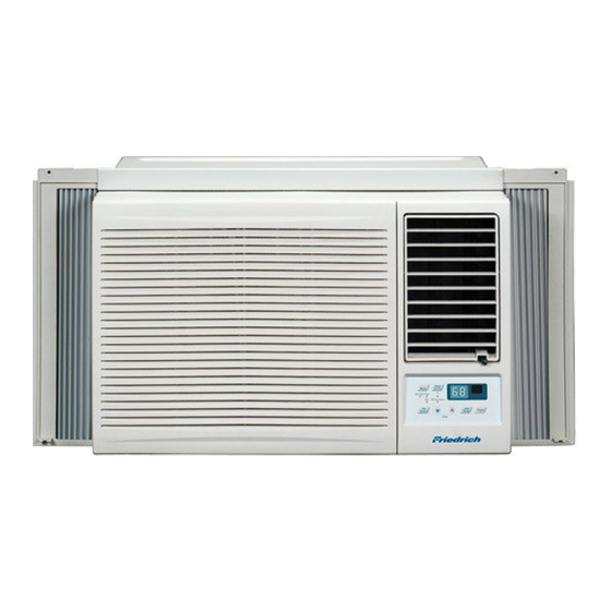
Page 1: Room Air Conditioner
Room Air Conditioner Service and Parts CP10E 10 CP10 CP12 SVC PARTS 2008 (07/08) Manual Timer Mode Fan Only Cool Money Saver ® Auto Power Speed Swing Temp CP12E 10... -
Page 2: Table Of Contents
TABLE OF CONTENTS Safety Precautions...3 Dimensions ...6 Outside Dimensions ...6 Product Specifications ...7 Operation ... 8 How to Operate Your Friedrich CP... 9 Disassembly ... 10 Mechanical Parts... 10 Air Handling Parts ...11 Electrical Parts ...12 Refrigerating Cycle...13 Schematic Diagram...16 Wiring Diagram...16... -
Page 3: Safety Precautions
Safety Precautions To prevent injury to the user or other people and property damage, the following instructions must be followed. Incorrect operation due to ignoring instructions will cause harm or damage. The seriousness is classified by the following indications. WARNING This symbol indicates the possibility of death or serious injury. - Page 4 Do not operate or stop the unit by inserting or pulling out the power plug. • It will cause electric shock or fire. Use the air conditioner on a single outlet circuit.(see page 7.) Do not share the outlet with other appliances. •...
-
Page 5: Service Manual
Leaving it damaged couldresult in the air conditioner falling out of the window, creating a safety hazard. Do not clean the air conditioner with water. • Water may enter the unit and degrade the insulation. It may cause an electric shock. -
Page 6: Dimensions
This symbol alerts you to the risk of electric shock. This symbol alerts you to hazards that could cause harm to the air conditioner. This symbol indicates special notes. NOTICE Outside Dimensions 525(20 ") 470(18 ") 6 Room Air Conditioner... -
Page 7: Product Specifications
DRAIN SYSTEM OUTSIDE DIMENSION (inch) (W x H x D) (mm) * DB:Dry Bulb ** WB:Wet Bulb CP10E10 10,000 (Btu/h) ( C) 490g(17.3oz) PROPELLER TYPE FAN WITH SLINGER RING HORIZONTAL LOUVER (UP & DOWN), AUTOSWING LOUVER (RIGHT&LEFT) INTERNAL THERMAL PROTECTOR... -
Page 8: Operation
Operation Operation • DESIGNED FOR COOLING ONLY • POWERFUL AND INCREDIBLE COOLING • TOP-DOWN CHASSIS FOR THE SIMPLE INSTALLATION AND SERVICE • BUILT-IN ADJUSTABLE THERMOSTAT • WASHABLE ONE-TOUCH FILTER • COMPACT SIZE Location and Function of Controls Service Manual 8... -
Page 9: How To Operate Your Friedrich Cp
Timer Mode Fan Only Cool Money Saver ® Speed Temp Room Air Conditioner Auto Power Swing 6. AUTO SWING This button can automatically control the air flow direction(left+right). A ir Power P urifier Temp Fan S peed Mode T imer... -
Page 10: Disassembly
Disassembly — Before the following disassembly, POWER SWITCH set to OFF and disconnect the power cord. Mechanical Parts 1. FRONT GRILLE 1. Open the lnlet grille upward or downward. 2. Remove the screw which fastens the front grille. 3. Pull the front grille from the right side. 4. -
Page 11: Air Handling Parts
5. Remove the clamp which secures the fan. 6. Remove the fan and then pull out the shroud. (See Figure 22) 7. Re-install by referring to the removal procedure. 11 Room Air Conditioner Figure 20 Figure 21 Figure 22 —7—... -
Page 12: Electrical Parts
3. MOTOR 1. Remove the cabinet. 2. Remove the evaporator. 3. Remove the orifice. 4. Remove the blower. 5. Remove the fan. 6. Remove the control box cover and housing of the motor in the control box. 7. Remove the 2 screws which fasten the motor from the mount motor. -
Page 13: Power Cord
MODEL : TOUCH & REMOTE CONTROL TYPE MODEL 1. Remove the control box. 2. Remove the screw which fasten control panel from control box. 3. Remove the screw which located in the front. 4. Open the bottom side of control box. 5. -
Page 14: Capillary Tube
Close valves A and B, and observe vacuum gauge for a few minutes. A rise in pres- sure would indicate a possible leak or moisture 14 Room Air Conditioner Figure 29 remaining in the system. With valves A and B closed, stop the vacuum pump. - Page 15 Disassembly Equipment needed: Vacuum pump, Charging cylinder, Manifold gauge, Brazing equipment. Pin-off tool capable of making a vapor-proof seal, Leak detector, Tubing cutter, Hand Tools to remove components, Service valve. Figure 30B-Charging Figure 30A-Pulling Vacuum Service Manual 15...
-
Page 16: Schematic Diagram
Schematic Diagram Circuit Diagram MODEL : TOUCH & REMOTE CONTROL TYPE MODEL LOCATION 16 Room Air Conditioner DESCRIPTION POWER CORD ASSEMBLY FAN MOTOR COMPRESSOR DISPLAY P.W.B ASSEMBLY MAIN P.W.B ASSEMBLY THERMISTOR CAPACITOR OWERLOAD PROTECTOR Q'TY PER SET... -
Page 17: Electronic Control Device
Schematic Diagram Electronic Control Device 17 Room Air Conditioner... -
Page 18: Components Location(For Main P.w.b Asm)
Schematic Diagram Components Location(For Main P.W.B ASM) Service Manual 18... -
Page 19: Troubleshooting Guide
This will help you to understand the refrigeration cycle and the flow of the refrigerant in the cooling cycle. EVAPORATOR COILS COMPLETE LIQUID BOIL OFF POINT COOLED ROOM AIR HEAT LOAD LIQUID PRESSURE DROP 19 Room Air Conditioner ROOM AIR CONITIONER CYCLE OF REFRIGERATION SUCTION LINE COOL LOW PRESSURE VAPOR OUTSIDE COOLING AIR FOR REFRIGERANT PASS THROUGH MOTOR... -
Page 20: Troubleshooting Guide
Troubleshooting Guide In general, possible trouble is classified in two kinds. The one is called Starting Failure which is caused from an electrical defect, and the other is ineffective Air Conditioning caused by a defect in the refrigeration circuit and improper application. Unit runs but poor cooling. - Page 21 Defect of compressor capacitor. Capacitor check. Replacement. Irregular motor resistance ( ) Irregular motor insulation ( ) Replacement of compressor (Motor damaged). 21 Room Air Conditioner Fails to Start Improper thermistor setting Loose terminal connection Improper wiring Check of circuit breaker and fuse.
- Page 22 MODEL : BG8000ER, WG8000RY4, WG1000RY4 ELECTRIC PARTS TROUBLESHOOTING GUIDE: Possible Trouble 1 Is the Trans input power AC 115V? Is the Trans output power about AC 14V? Is output Voltage of IC01D DC 12V? Is output Voltage of IC02D DC 5V? Is the reset circuit all right? (The No.14 of Micom is 5V.)
- Page 23 IC01M 0V? • Check the RY-Hi or RY-Lo. • Check the wiring diagram. 23 Room Air Conditioner • The compressor does not operate. • Set the Temp. setting to lower Temp. Is the voltage N0.7 of IC01M DC 5V? •...
- Page 24 Possible Trouble 5 Is the voltage of Battery about over 2.3V? Is the voltage No.16 of CN-DISP1 on Main P.W.B Ass'y DC 5V? Is the connection of CN-DISP1 all right? • Exchange Receiver Ass'y. Possible Trouble 6 Is the IC01G all right? Is the connection of CN-DISP1 all right? Does the Q01G,...
- Page 25 ROOM AIR CONDITIONER VOLTAGE LIMITS NAME PLATE RATING 115V ± 10% COMPLAINT Fan motor will not run. No power Power supply cord Rotary switch Wire disconnected or connection loose Capacitor (Discharge capacitor before testing.) Will not rotate Fan motor runs.
- Page 26 COMPLAINT Fan motor noise. Blower Loose set screw Worn bearings Compressor will not run, Voltage fan motor runs. Wiring Thermistor Rotary Thermostat Capacitor (discharge capacitor before servicing.) Compressor Overload CAUSE If cracked, out of balance, or partially missing, replace it. If cracked, out of balance, or partially missing, replace it.
- Page 27 Air filter Unit undersized Excessive noise Blower or fan Copper tubing 27 Room Air Conditioner CAUSE Check the voltage. See the limits on the preceding page. If voltage is not within these limits, call an electrician. Check overload, if externally mounted.
-
Page 28: Exploded View
Exploded View Exploded Vie w 130910 554030 749740 731273 148000 359011 346811 352380 W48602 349600 149980 359012 267110 354210 W48602 349001 349480 567502 152302 135303 130410 554160 550140 135312 147581 W5210E-2 249950 W5210E-1 567480 552102 W0CZZ 552113 268711-1 238310 352113 146812 264100 35211A... -
Page 29: Replacement Parts List
LocNo CP10E10 130410 67302929 349001 67303508 130910 67303715 135312 67306018 135303 67306111 135500 67304701 147581 67306209 147582 67306265 149980 67303103 152302 67304308 238310 67500143 567480 67307806 264100 67300022 267110 67307704 249950 67305515 237200 67305514 268711-1 67307623 268711-2 67307622 146812 67300902... - Page 30 Use Factory Certified Parts... FRIEDRICH AIR CONDITIONING CO. Visit our web site at www.friedrich.com Post Office Box 1540 • 4200 N. Pan Am Expressway • San Antonio, Texas 78295-1540 • (210) 357-4400 • FAX (210) 357-4490 CP10 CP12 SVC PARTS 2008(07/08)
Need help?
Do you have a question about the CP10E10 and is the answer not in the manual?
Questions and answers