ATN PS-22 Operator's Manual
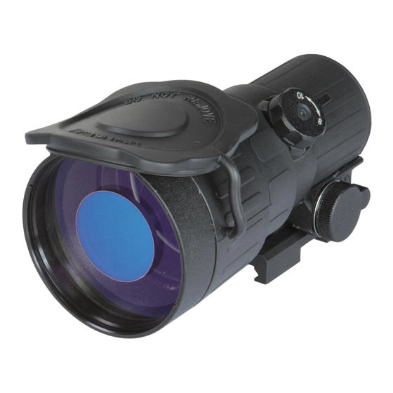
Night vision front sight
Hide thumbs
Also See for PS-22:
- User manual (8 pages) ,
- Operator's manual (64 pages) ,
- User manual (13 pages)
Table of Contents
Advertisement
Quick Links
Download this manual
See also:
User Manual
ATN PS-22
NIGHT VISION FRONT SIGHT
operator'S manUal (atn pS-22) revISIon 6 - marCh 2011
o p e r a t o r ' s m a n u a l
Important Export Restrictions ! Commodities,
products, technologies and services contained in
this manual are subject to one or more of the export
control laws and regulations of the U.S. Government
and they fall under the control jurisdiction of either the
US Department of State or the US BIS-Department
of Commerce. It is unlawful and strictly prohibited
to export, or attempt to export or otherwise transfer
or sell any hardware or technical data or furnish any
service to any foreign person, whether abroad or
in the United States, for which a license or written
approval of the U.S. Government is required, without
first obtaining the required license or written approval
from the Department of the U.S. Government having
jurisdiction. Diversion contrary to U.S. law is prohibited.
Advertisement
Table of Contents

Related Manuals for ATN PS-22


Summary of Contents for ATN PS-22
- Page 1 ATN PS-22 NIGHT VISION FRONT SIGHT operator’S manUal (atn pS-22) revISIon 6 - marCh 2011 o p e r a t o r ’ s m a n u a l Important Export Restrictions ! Commodities, products, technologies and services contained in this manual are subject to one or more of the export control laws and regulations of the U.S.
- Page 2 Corp. atn Corp. assumes no responsibility or liability for any errors or inaccuracies that may appear in this book.
-
Page 3: Safety Summary
STUDY CAREFULLY THIS MANUAL BEFORE TURNING ON AND OPERATING THIS PRODUCT. CAUTIONS The ATN PS-22 night vision front sight is a precision electro- optical instrument and requires careful handling. To provide safe use of the sight the following instructions should be observed: •... - Page 4 NOTES • Do not test the device in daylight conditions even with the daylight filter/lens cap on for more than ten (10) minutes. • To protect the device from damage do not direct it to the bright light sources (a fire, headlights of the automobile, lan- terns, etc.).
- Page 5 EqUIPMENT LIMITATIONS to avoid physical and equipment damage when using the atn pS-22, carefully read and understand the following equip- ment limitations. • The equipment requires some night light (moonlight, starlight, etc.) to operate. the level of equipment performance depends upon the level of light.
-
Page 6: Table Of Contents
1.1.1. Scope 1.1.2. reports 1.1.3. Storage 1.1.4. Warranty 1.2. Description and Data 1.2.1. Description 1.2.2. pS-22 Standard Components and optional equipment SECTION II. OPERATING INSTRUCTIONS 2.1. Installation Procedures 2.1.1. Quick release mount 2.1.2. attachment to Day Scope objective 2.1.3. Extender Focus Knob 2.2. - Page 7 4.1.1. purpose of pmCS 4.1.2. pmCS procedures 4.2. Troubleshooting 4.2.1. General 4.2.2. troubleshooting procedures 4.3. Maintenance Procedures 4.3.1. PS-22 Maintenance 4.3.2. Cleaning Procedures 4.3.3. Tube Maintenance / Replacement Appendix A. Estimation of Ambient Illumination Level Appendix B. Spare Parts List Appendix C.
-
Page 9: Section I. Introduction
SECTION I INTRODUCTION... -
Page 10: General
1.1.1. SCOPE this manual contains instructions for use in operating and main- taining the atn pS-22 night vision Front Sight. throughout this manual, the atn pS-22 will be referred to as the sight or the pS-22. 1.1.2. REPORTS reports from the user on recommendations for improvements are encouraged. -
Page 11: Warranty
Customer’s sole and exclusive remedy. this warranty does not cover a product (a) used in other than its normal and customary man- ner;... - Page 12 Customer; ATN’s obligations under this Agreement extend solely to the Customer. ATN’s liability hereunder for damages, regardless of the form or action, shall not exceed the fees or other charges paid to ATN by the customer or customer’s dealer.
-
Page 13: Description And Data
1.2. DESCRIPTION AND DATA 1.2.1. DESCRIPTION A. Purpose the pS-22 is an effective night vision system that mounts forward of an existing riflescope/spotting scope (further referred to as a scope) adding night vision capabilities to daytime target acquisi- tion platform. advisable dayscope magnification is 1X to 6X (2.5X to 4X is optimum). - Page 14 • The sight requires some night light (moonlight, starlight, etc.) to operate. night light is reduced by such factors as passing cloud cover and objects that produce shadows.
- Page 15 TABLE 1-2. MECHANICAL DATA ITEM DATA 150 mm x 80 mm x 72 mm Dimensions(length x Width x height) Weight: without Battery 0.64 kg with remote Control, light 0.7 kg Suppressor and Battery height of the Sight axis above arm rail: with Issued mount 40 mm TABLE 1-3.
-
Page 16: Ps-22 Standard Components And Optional Equipment
Immersion 10 m for 30 minutes 1.2.2. PS-22 STANDARD COMPONENTS AND OPTIONAL EqUIPMENT the pS-22 standard components are shown in Figure 1-1 and pre- sented in table 1-6. FIGURE 1-1. PS-22 STANDARD COMPONENTS TABLE 1-6. PS-22 STANDARD COMPONENTS ITEM... - Page 17 ITEM DESCRIPTION light Supressor for trijicon aCoG scopes light Supressor for the scopes with 42-63 mm lens diameter remote Control Cr123a type battery IR Illuminator IR450 Kit picatinny Quick release mount picatinny rail Qrm Wrench 2.5 mm Allen Key operator’s manual Shipping/Storage Case is shown in Figure 1-2 and listed in Table 1-7.
- Page 18 Figure 1-3 and listed in table 1-8. TABLE 1-8. PS-22 OPTIONAL EqUIPMENT ITEM DESCRIPTION PART CODE Scope mounting System #1 aCDnpS22Sm01 Scope mounting System #2 aCDnpS22Sm02 Scope mounting System #3 aCDnpS22Sm03 Scope mounting System #4...
-
Page 19: Section Ii. Operating Instructions
SECTION II OPERATING INSTRUCTIONS... -
Page 20: Installation Procedures
Difference of the axes position more than 3 mm is not re-com- mended. Measure the height of the riflescope axis above the rail. If the difference in the axis heights of the PS-22 and riflescope is more than 3 mm it is necessary to replace riflescope mounting rings or base by proper ones. -
Page 21: Attachment To Day Scope Objective
2-1. For example, you will need the scope mounting system #1 and 25.4 mm insert in order to mount the pS-22 onto the front lens of leupold 1.5-5x20 pr. NOTE If scope mounting system is used, the issued weapon mount should be removed. - Page 22 SCreW m2X2.5 FIGURE 2-2. SCOPE MOUNTING SYSTEM 5. loosen the fixing nut of the mounting system. 6. Slide the pS-22 with attached mounting system onto the objec- tive lens of the day scope until full stop. DaYSCope oBjeCtIve lenS FIXInG nUt...
- Page 23 10. rotate the locking ring of the scope mounting system towards the pS22 output lens and tighten it. It will work as a lock nut to fix the pS22 position on the day scope. 11. apply a small amount of thread locker on threads and tighten the two screws m2x2.5 in the locking ring.
- Page 24 Ir450 pS22 with leupold Daytime Scope pS22 with Qrm and trijicon aCoG with Scope mounting System pS22 with Scope mounting pS22 with Spotting Scope with System and Leupold CQ/T Scope mounting System FIGURE 2-5. PS-22 MOUNTING ExAMPLES...
-
Page 25: Extender Focus Knob
2.1.3. ExTENDER FOCUS KNOB If desired the pS22 has an optional extender focus knob that can be attached to the focus ring. this knob allows for extra leverage for ease of focus adjustment. to install the extender focus knob: 1. Unscrew the fixing screw. replace it to short fixing screw(1) from extender focus knob kit. -
Page 26: Operating Procedures
2.2. OPERATING PROCEDURES 2.2.1. GENERAL this section contains instructions for placing the pS-22 in opera- tion. the function of controls is explained. CAUTION The PS-22 is a precision electro-optical instrument and must be handled carefully at all times. CAUTION Ensure the function switch is in the off position before installing a battery. - Page 27 Cap remote Control plUG FIGURE 2-8. PS-22 CONTROLS TABLE 2-2. PS-22 CONTROLS CONTROLS FUNCTION StB — the sight is in standby mode. Function oFF — the sight is off. Switch on — the sight is on. Switch’s spring is loaded.
-
Page 28: Operating Procedures
CAUTION Bright sources such as light of fire, headlights, searchlights, etc. Can damage the PS-22. Take away the PS-22 from the bright sources that appear on the scene. 6. If the riflescope has focusing rings (parallax adjustment knob), adjust focus for parallax free image. -
Page 29: Stowage Of
Unscrew the battery cap and take out the battery. replace the battery cap. Do not store the pS-22 with the battery still in it. e) return the sight and all accessories to the case. 2.2.4. STOwAGE OF PS-22 1. ensure the pS-22 and all accessories are clean and dry before returning to storage case. -
Page 30: Installation And Use Of Accessories
2.3. INSTALLATION AND USE OF ACCESSORIES 2.3.1. 7/8” wEAVER MOUNT Optional 7/8” Weaver Mount is used for installation the PS-22 on 7/8” Weaver rail instead of the issued mount. NOTE If using weaver rails, please consult your gunsmith for modifica- tion to rail. -
Page 31: Picatinny Rail
3. place the control key on the fore-end of rifle stock and fix it with velcro tape. 4. to turn on the pS-22 turn the function switch in standby (StB) position. press and hold the control key. 5. after disconnecting the remote control screw the cap onto the plug. -
Page 32: Platform Ring
2-12). 2.3.6. B.A.M. SYSTEM B.a.m. system (Boresight attachment mount) is used to install the pS-22 night vision Front Sights and the dayscope on the rifles hav- ing short mounting mIl-StD-1913 rail. there are three advantages of the system: • Low position of the sight and dayscope (36 mm above the rail). - Page 33 • Resistance on the rifle with vigorous recoil. Bam System Installation: 1. Slightly loosen the two fixing screws (1) on the mount base (2). 2. place the base on the mount of the fire arm (3). 3. tighten the fixing screws of mount base. 4.
-
Page 34: Ir450 Illuminator
Staying in the dark, switch on your night vision device. If the visibility is low, you may use atn Ir450 to improve the situation. Still, you should remember that the Ir illuminator is just a source of infrared light so the greater is the chosen range of observation, the lesser its brightness becomes. - Page 35 ALLEN KEY FIGURE 2-14. IR450 ILLUMINATOR the atn Ir450 is powered with one Cr123a lithium battery. to install the battery unscrew the cap of the battery housing and in- sert the battery following the polarity arrows marked on the hous- ing.
-
Page 36: Day Scope Light Suppressor
You can change the position of WrenCh the Ir control panel to meet your your needs. the wrench that is in- to looSen nUt cluded in the set, is used to loosen the nut located on the body of the Ir. -
Page 37: Section Iii. Operational Defects
SECTION III OPERATIONAL DEFECTS... -
Page 38: Zeroing Operational Defects
operation. -
Page 39: Edge Glow
If you believe a blemish is a cause for rejection, warranty or repair please ATN or point of purchase for warranty/ repair procedures. - Page 40 If the bright spot remains, re- turn the atn pS-22. Bright spots usually go away when the light is blocked out. make sure any bright spot is not simply a bright area in the scene you are viewing.
- Page 41 C. Black Spots these are cosmetic blemishes in the image intensifiers or dirt or debris between the lenses. Black spots are acceptable as long as they do not interfere with viewing the image. no action is required if this condition is present unless the spots interfere with the us- ability of the device.
- Page 42 E. Chicken wire an irregular pattern of dark thin lines in the field of view either throughout the image area or in parts of the image area (Figure 3-5). Under the worst-case condition, these lines will form hexag- onal or square-wave shaped lines. this is typically viewed in high light conditions.
-
Page 43: Section Iv. Maintenance Instructions
SECTION IV MAINTENANCE INSTRUCTIONS... -
Page 44: Preventive Maintenance Checks And Services (Pmcs)
4-1 are a systematic inspection of the pS-22 that will enable you to discover defects that might cause the sight to fail on a mission. - Page 45 TABLE 4-1. PREVENTIVE MAINTENANCE CHECKS AND SERVICES SEq. ITEM TO NOT FULLY MISSION CHECKING PROCEDURE CHECK CAPABLE IF: objective Check to ensure the ob- objective lens loose. lens jective lens is not loose. Check to ensure: — the focus ring cannot Fo c u s r i n g a b l e to be moved along the sight move along sight body.
- Page 46 NOT FULLY MISSION CHECKING PROCEDURE CHECK CAPABLE IF: OPERATIONAL CHECKS CAUTION Operate the PS-22 with Front Lens Cap on or under dark conditions. Inser t the batter y. turn the switch to on position. Function look for green glow in out- Green glow absent.
-
Page 47: Troubleshooting
4.2.1. GENERAL this section contains information for locating and removal most of the pS-22 operating troubles which may occur. each malfunction for an individual component or assembly is followed by a list of tests or inspections that will help determine probable causes and cor- rective action to take. - Page 48 TABLE 4-2. TROUBLESHOOTING PROCEDURES PROBLEM PROBABLE CAUSE CORRECTIVE ACTION Cannot achieve objective and output Clean thoroughly the lenses the sharp image lenses dirty. surfaces. of the object. loosen and remove three screws m2x2.5. Screw the locking ring. rotate focus Fo c u s r i n g a b l e to r i n g s l i g h t l y c l o c k w i s e / move along the sight counterclockwise.
-
Page 49: Maintenance Procedures
4.3. MAINTENANCE PROCEDURES 4.3.1. PS-22 MAINTENANCE the pS-22 maintenance consists of external inspection of its components for serviceability, cleaning and installation of the standard and optional accessories. maintenance instructions covered elsewhere in this manual (pmCS, troubleshooting, etc.) are not repeated in this section. -
Page 50: Tube Maintenance / Replacement
- Lock-ring spanner wrench; - Focus wrench; - purge kit. table 4-3 lists requirements for the equipment needed for pS-22 focusing and aligning after tube replacement. TABLE 4-3. EqUIPMENT FOR PS-22 FOCUSING AND ALIGNING. ITEM... - Page 51 Below the actions for «GlaSS/GLASS» tube only are listed: - accurately separate the compensator glass (Figure 4-1, 9) from the tube for second using. - Unsolder tube wires from the board on the tube end (Figure 4-2). accurately separate the board (Figure 4-2, 1) from the tube for second using.
- Page 52 NOTE If special attenuator filter is used, testing and alignment pro- cedure could be done in the normal illuminated room and the collimator pattern illuminator could have only daytime mode. Attenuator filter have to be neutral glass filter with density 4 to 5.
- Page 53 FIGURE 4-1. TUBE REPLACEMENT FIGURE 4-2. INSTALLATION OF THE BOARD TO THE TUBE FIGURE 4-3. OBjECTIVE LENS FOCUSING 4-11...
- Page 54 - rotate the focus ring (Figure 4-3, 4) counterclockwise to open the objective thrust ring (Figure 4-3, 2). not allow to fall the threaded segments out. - loosen three fixing screws (Fiigure 4-3, 3). - move the focus ring (Figure 4-3, 4) towards the objective lens. - rotate the objective lens (Figure 4-3, 1) and the thrust ring (Figure 4-3, 2) together to achieve sharp image of collimator pattern.
- Page 55 - replace the output lens assembly (Figure 4-1, 11) and tighten three adjustment screws (Figure 4-1, 3) lightly. - Screw and tighten lightly the lock ring (Figure 4-1, 14). G. Output Lens Focusing - Switch the collimator pattern illuminator on in nighttime mode. - put the sight onto the mounting rail, switch it on and rotate focus ring (Figure 4-3, 4) to achieve sharp image.
-
Page 56: Appendix A. Estimation Of Ambient Illumination Level
APPENDIx A (Reference) ESTIMATION OF AMBIENT ILLUMINATION LEVEL TABLE A-1. STANDARD NATURAL LIGHT CONDITIONS AND ILLUMINATION VALUES STANDARD NATURAL LIGHT ILLUMINATION VALUE, CONDITIONS Quarter moon 0.05 Full moon 0.30 late twilight sky 1.00 twilight sky 10.00 overcast sky in the daytime 500.00... - Page 57 SPARE PARTS LIST the Spare parts list is an illustrated catalog of main parts and assemblies completing the night vision Sight pS-22, here in after referred to as pS-22. therefore, in case of failure of any part or assembly User could replace it by ordering the corresponding part/assembly from the Spare parts list.
- Page 58 TABLE B-1. ATN PS-22 SPARE PARTS LIST PART NO. DESCRIPTION FIG. ITEM AT 146541.714 plug Cap AT 146541.715 output lens assebly AT 146541.716 lock ring AT 146542.700 Accessories 1 (From the Kit) light Supressor for the scopes with AT 146542.710...
- Page 59 TABLE B-1. ATN PS-22 SPARE PARTS LIST PART NO. DESCRIPTION FIG. ITEM Scope mounting System Insert with AT 146534.752 30 mm diameter Scope mounting System Insert with AT 146534.753 38 mm diameter Scope mounting System Insert with AT 146534.754 42 mm diameter Scope mounting System Insert with AT 146534.755...
- Page 60 TABLE B-1. ATN PS-22 SPARE PARTS LIST PART NO. DESCRIPTION FIG. ITEM AT 146533.706 Day Scope light Suppressor AT 146533.751 Boresight attachment mount (Bam) FIGURE B-1. NIGHT VISION SIGHT FIGURE B-2. ACCESSORIES 1 (FROM THE KIT) FIGURE B-3. ACCESSORIES 2 (OPTIONAL)
-
Page 61: Appendix C. How To Select Scope Mounting System
REqUIRED FOR YOUR DAYTIME SCOPE By selecting the appropriate Scope mounting System (with In- serts) you can mount the pS-22 onto a daytime scope with an objective tube diameter from 25 to 62 mm. at the table 2-1 Scope mounting System sizes (#1-6) and Insert sizes for different scope examples are provided. -
Page 62: For Technical Information
FOR TECHNICAL INFORMATION ATN CORP. 1341 San mateo avenue South San Francisco, Ca 94080 (800) 910-2862 (650) 989-5100 tel. (650) 875-0129 fax www.atncorp.com info@atncorp.com InFo-1... - Page 63 InFo-1...
- Page 64 800-910-2862, 650-989-5100; fax: 650-875-0129 European Office the following countries can use our toll free number: 00 800 9102-8620 austria, France, Germany, holland, Italy, Spain, Sweden, Switzerland For other countries, please use 38 048-7770214 or 38 048-7770345 www.atncorp.com ©2011 atn Corporation...
Need help?
Do you have a question about the PS-22 and is the answer not in the manual?
Questions and answers