
Related Manuals for Trane UV-SVN02B-EN

Summary of Contents for Trane UV-SVN02B-EN
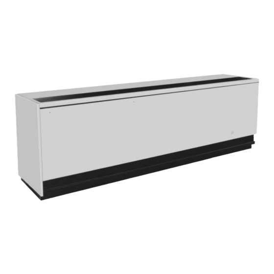
- Page 1 Installation Operation & Maintenance Vertical and Horizontal Classroom Unit Ventilators Order No: UV-SVN02B-EN Date: February 2005 UV-SVN02B-EN...
- Page 2 Notice Notice Warnings and Cautions appear at appropriate sections throughout this manual. Read these carefully. WARNING - Indicates a potentially hazardous situation which, if not avoided, could result in death or serious injury - Indicates a potentially hazardous situation CAUTION which, if not avoided, could result in minor or moderate injury.
-
Page 3: Table Of Contents
Contents General Information Receiving and Handling Installation Drawings Installation Location Considerations Unit Mounting Piping Installation Valves Wiring Electrical Data Maintenance Troubleshooting Accessories Wall Boxes Related Literature UV-SVN002-EN... -
Page 4: General Information
Configuration cooling coil connection during assem- OA/RA Damper The classroom unit ventilator is config- bly per model number selection. Trane unit ventilators are equipped with ured in both a: dual blade type mixing damper to • horizontal (ceiling mount) Fanboard ensure proper modulation and mixing •... - Page 5 When reaching the damper tor is also available when other than end position, the actuator automatically Trane controls is required. See Table 1 stops. The gears can be manually disen- for technical data of the OA/RA actua- gaged with a button on the actuator tor.
- Page 6 General Information Modulating Water Valves (Option) Table 3: Technical Data for Table 4: Technical Data for Isolation The modulating control valve option Modulating Water Valves Water Valves provides optimum control of hot and chilled water flow in various heating and cooling applications. They are designed to provide sinusoidal valve actuator travel and operate silently, resisting water hammer.
- Page 7 General Information Unit Ventilator Controls Trane offers Direct Digital Controls for In addition, air conditioning installa- Controls are provided either by Trane as the unit ventilator. The ZN520 (See tions will usually provide a means of a factory-mounted option or furnished...
-
Page 8: Receiving And Handling
Receiving and Handling ordered for vertical units, the The unit ventilator is packaged in clear tions or shipping damage. stretch wrap and protective to allow for panel will already be mounted to immediate visual inspection. Vertical the unit. 7. Remove all applicable knock- units are also shipped with a protective outs for coil piping and cardboard cover to help prevent... -
Page 9: Installation Drawings
Installation Drawings VUV 15-1/4” Depth Figure 6: Standard depth vertical unit ventilator dimensional data 1 3/4" 15 1/4" (2)-10 1/2" x 7 1/4" K.O.. FOR PIPING OR 1 3/8" 2 1/2" ELECTRICAL 8 7/8" (2)-6" x 6" K.O. FOR PIPING 20"... - Page 10 Installation Drawings VUV 16-1/4” Depth Figure 7: 1-inch falseback vertical unit ventilator dimensional data 16 1/4" (2)-10 1/2" x 7 1/4" K.O.. FOR PIPING OR 1 3/8" 3 1/2" ELECTRICAL 8 7/8" (2)-6" x 6" K.O. FOR PIPING 20" OR ELECTRICAL 10 7/8"...
- Page 11 Installation Drawings VUV 21-1/4” Depth Figure 8: 6-inch falseback vertical unit ventilator dimensional data 1 3/4" 21 1/4" (2)-10 1/2" x 7 1/4" K.O.. FOR PIPING OR 1 3/8" 8 1/2" ELECTRICAL 8 7/8" (2)-6" x 6" K.O. FOR PIPING 20"...
- Page 12 Installation Drawings VUV Ducted Inlet Figure 9: 6-inch falseback vertical unit ventilator with ducted inlet dimensional data (2)-10 1/2" x 7 1/4" K.O.. FOR PIPING OR 1 3/4" 21 1/4" ELECTRICAL 1 3/8" 8 1/2" 8 7/8" (2)-6" x 6" K.O. FOR PIPING 20"...
- Page 13 Installation Drawings VUV Ducted Inlet/Discharge Figure 10: 6-inch falseback vertical unit ventilator with ducted inlet and return air discharge dimensional data (2)-10 1/2" x 7 1/4" K.O.. FOR PIPING OR 21 1/4" ELECTRICAL 1 3/8" 8 1/2" 8 7/8" (2)-6" x 6" K.O. FOR PIPING 20"...
- Page 14 Installation Drawings HUV Ducted Front Discharge Figure 11: Horizontal unit ventilator with ducted front discharge dimensional data. Sizes 075-150 2"-DIA K.O. 7/8"-DIA K.O. FOR PIPING FOR ELECTRICAL F.A. UPPER BACK R.A. LOWER BACK 2 3/8" 4 7/8" 17 1/8" 17 1/8" BACK VIEW SIDE VIEW 12 1/8"...
- Page 15 Installation Drawings HUV Ducted Front Discharge Figure 12: Size 200 horizontal unit ventilator with ducted front discharge dimensional data 2"-DIA K.O. 7/8"-DIA K.O. FOR PIPING FOR ELECTRICAL F.A. UPPER BACK R.A. LOWER BACK 2 3/8" 4 7/8" 17 1/8" 72" 17 1/8"...
-
Page 16: Installation Drawings
Installation Drawings HUV Bottom Double Deflection Discharge Figure 13: Double deflection discharge horizontal unit ventilator dimensional data. Sizes 075 - 150 2"-DIA K.O. 7/8"-DIA K.O. 3/4" FOR PIPING FOR ELECTRICAL 4" R.A. LOWER BACK 2 3/8" 7 1/4" 4 7/8" 5 1/8"... - Page 17 Installation Drawings HUV Bottom Double Deflection Discharge Figure 14: Double deflection discharge horizontal unit ventilator dimensional data. Size 200 2"-DIA K.O. 7/8"-DIA K.O. 3/4" FOR PIPING FOR ELECTRICAL 5" R.A. LOWER BACK 2 3/8" 9 1/4" 4 7/8" 5 1/8" 17 1/8"...
- Page 18 Installation Drawings HUV Inlet Arrangements Figure 15: Supply/return air arrangements for the HUV DIGIT 20 = A DIGIT 20 = F DIGIT 20 = L FA DUCT TOP FA DUCT UPPER BACK 100% RA DUCT LOWER BACK w/RA DUCT LOWER BACK w/RA DUCT LOWER BACK DIGIT 20 = B DIGIT 20 = G...
-
Page 19: Installation
NOTE: Measurements in Figures smooth and level. A wall slightly installer. Trane recommends 3/8” 6-10 do not include adjusted out of level may cause problems rods for hanging suspension. -
Page 20: Unit Mounting
Installation Note: Unit must remain level. Coils Vertical Unit Ventilator Vertical Unit Ventilator and drain pans inside the unit are Subbase pitched properly for draining before The 1/2” mounting or anchoring holes A subbase may be used to increase the shipment. - Page 21 Installation Recessed vertical units (Option) Recessing The optional recessing flange assembly Flanges includes pre-cut flanges, corner transi- tion pieces, mounting screws, filler Corner pieces and pressure sensitive gaskets. Transition Piece Refer to Figure 19 for a typical vertical Figure 19: Recess installation.
- Page 22 Installation Horizontal Unit Ventilator Figure 20: Preparing the horizontal classroom ventilator for lifting and installation. The horizontal unit ventilator may be attached directly to the ceiling or sus- pended from the ceiling by hangers. Hanger rods should be at least 3/8’’ diameter steel to support unit weight, as given in Table 5.
- Page 23 Installation Figure 21: Recess flange installation around horizontal Horizontal Recessed Mounting unit ventilator access panel and inlet The recessing flange assembly includes pre-cut Supply Air Supply Air flanges, corner transition pieces, mounting screws, Grille filler pieces and pressure sensitive gaskets. Refer Recessing Flange to Figures 21 &...
-
Page 24: Piping Installation
1. Supply and return connections are located on the same end of each coil. 2. All Trane piping packages have union connections; all units with piping packages by others have sweat connections. 3. Coil connections are sweat except steam coils, which are threaded... - Page 25 9 1/2" 7 1/2" 9 1/2" CROSSOVER PIPING IS AVAILABLE FOR A, H AND D COILS. FOR ALL D (4-PIPE) COILS, TRANE PROVIDES THE CROSSOVER FOR THE COLD WATER ONLY. THE CROSSOVER PIPE IS FACTORY INSULATED WITH 3/8"-THICK INSULATION. EXPANSION COMPENSATION BETWEEN THE FACTORY PIPING PACKAGE AND THE CROSSOVER PIPING IS ACHIEVED USING A FLEX HOSE RATED AT 250 PSI WORKING PRESSURE.
- Page 26 Table 10. Typical Superheat brought into the swage and brazed. Charging Charts are shown in the Trane NOTE: A UL listing mark applied to a Trane recommends the use of nitrogen Service Facts found in the condensing...
-
Page 27: Valves
Installation Steam Piping Figure 27: Steam Piping When air, water or another product is heated, the temperature or heat trans- fer rate can be regulated by a modulat- Temp. Regulating Valve ing steam pressure control valve. Since pressure and temperature do not vary at the same rate as load, the steam trap capacity, which is determined by Coil... - Page 28 Installation and diverting through end ports A or B. Wiring Figure 29: Cartridge removal tool In mixing applications the valve is A controller and a separate transformer installed with inlet to A or B and outlet is required to operate each valve (See through AB.
- Page 29 Installation Isolation Valves 6. Press the actuator and valve body Figure 34: until it secures together. Installation Removing The valve can be mounted in any posi- isolation Soldering procedures are as follows: tion on a vertical line. If the valve is valve 1.
- Page 30 Installation Heating Coils with Direct Wiring Split System Start-Up Expansion Cooling After all piping and wiring has been completed, follow the instructions pro- Heating options for direct expansion WARNING vided with the condensing unit for con- cooling in the unit ventilator are hot Hazardous Voltage! trol testing and system start-up.
-
Page 31: Wiring
Supply Power one and two speed control. Terminal Supply power wiring is to be connected wiring is provided by Trane and the to the following line terminals in the Table 10: Hi-ESP Motor Data* actual components used for a particular right hand end pocket: installation may differ. -
Page 32: Wiring Diagrams
Wiring Diagrams Figure 38: Field Installed Controls, 120V, 1 Speed Unit Mounted Fan Switch UV-SVN002-EN... - Page 33 Wiring Diagrams Figure 39: Field Installed Controls, 120V, 2 Speed Unit Mounted Fan Switch UV-SVN002-EN...
-
Page 34: Wiring Diagram
Wiring Diagram Figure 40: Field Installed Controls, Horizontal UV, 120V, 1 Speed Wall Mounted Fan Switch UV-SVN002-EN... - Page 35 Wiring Diagram Figure 41: Field Installed Controls, Horizontal UV, 120V, 2 Speed Wall Mounted Fan Switch UV-SVN002-EN...
- Page 36 Wiring Diagrams Figure 42: Power Diagram For 208V or 240V. 3-Phase, 3 Wire Electric Heat UV-SVN002-EN...
- Page 37 Wiring Diagram Figure 43: Power Diagram For 480V. 3-Phase, 4-Wire Electric Heat NOTE: Important! Incoming power to the unit ventilator is 3-phase, 4-wire for a 480- volt system. The system contains 5 conductors: 3- hot, 1-neutral and 1-equip- ment ground. The neutral line can not be used as the equipment ground.
- Page 38 Wiring Diagrams Figure 44: Power Diagram For 480V. 3-Phase, 4-Wire Electric Heat UV-SVN002-EN...
- Page 39 Wiring Diagrams Figure 45: End Device Package 120V, 4 Pipe Hot Water - Chilled Water UV-SVN002-EN...
- Page 40 Wiring Diagrams Figure 46: End Device Package 120V, Hot Water - DX Cooling UV-SVN002-EN...
- Page 41 Wiring Diagrams Figure 47: 208V or 240V. 3-Phase, 3 Wire Electric Heat - DX Cooling UV-SVN002-EN...
-
Page 42: Electrical Data
1/3 (.33) 1/6 (.17) 1/3 (.33) 1/6 (.17) 1/2 (.50) 1/4 (.25) 1/2 (.50) 1/4 (.25) 3/4 (.75) 1/3 (.75) UV with Controls For Trane Volts Amps Controls, add the following 0.94 values to determine 0.55 TOTAL MCA 0.48 0.41 0.41... -
Page 43: Maintenance
Equipment Damage injury. Filters Do not operate unit without filters or The air filters supplied with Trane UV’s grille in place. Failure to do so may Service Access are specially designed for high lint con- cause equipment failure To access the unit for water balancing, tent. - Page 44 Filters - continued Removal of the Drain Pan There are a number of filters available The unit ventilators drain pan is remov- for use with the Trane Classroom Unit able for periodic cleaning or easy Ventilators. The following section access for maintenance/drainage explains maintenance and replacement issues.
- Page 45 Maintenance steps in reverse order, remembering to allow fanboard removal. Take note steps in reverse order. the pitch of the drain pan. of where these sensors are located Removal of the Fanboard & and replace them when reinstalling Lubrication: Fan Shaft the fanboard.
- Page 46 • Inspect and clean the drain pans is required, it should be ordered from every three months. The Trane Company. 3. If the motor or other internal parts of the actuator is damaged, replace the • Check the coils for ‘‘dirt’’ accumula- To replace the fan motor, complete the entire actuator assembly.
-
Page 47: Troubleshooting
5. On the hot water or steam type trouble still persists, contact the be in the open position. units, check the boiler pressure control supplier or the local Trane 4. Check for a clogged filter. If the or temperature to make sure Sales Office. - Page 48 If the damper or valve appears to be function- ing improperly, contact the control contractor or, if Trane controls, see CNT-SVX04A-EN (Tracer ZN520 Unit Controller IOP) for details on DDC controls.
-
Page 49: Accessories Wall Boxes
Accessories - Wall Boxes General Information General Instructions The following instructions are general Trane wallboxes are illustrated in recommendations for installing wall Figures 58 & 59 and each lists the intake boxes. Consult the architectural wall openings required for wallboxes. - Page 50 Accessories - Wall Boxes Figure 59: Vertical wallbox (V1, V3, V2 & V6) dimensions UV-SVN002-EN...
- Page 51 Accessories - Wall Boxes Installation in Masonry Walls Figure 60: Wallbox installation in masonry A typical method of installing the wall wall box in a masonry wall opening is illus- Interior Wall trated in Figure 60. w/ sheetrock Grout the top and bottom of the wall Outside box frame as noted.
-
Page 52: Related Literature
A business of American Standard Companies www.trane.com Stocking Location Inland Trane has a policy of continuous product and product data improvement and For more information, contact reserves the right to change design and specifications without notice. your local district office or...
Need help?
Do you have a question about the UV-SVN02B-EN and is the answer not in the manual?
Questions and answers