
Related Manuals for Drawmer TS1


Summary of Contents for Drawmer TS1
-
Page 1: Table Of Contents
Power Connection page 3 • Digital Module page 4 CONTROL DESCRIPTIONS • Analogue page 5 • Digital page 8 OPERATION page 9 IF A FAULT DEVELOPS page 12 CONTACTING DRAWMER page 12 TECHNICAL SPECIFICATION page 13 BLOCK DIAGRAM page 14... - Page 2 In the case of a valid warranty claim, your sole and exclusive remedy and Drawmer’s entire liability under any theory of liability will be to, at Drawmer’s discretion, repair or replace the product without charge, or, if not possible, to refund the purchase price to you.
-
Page 3: Safety Considerations
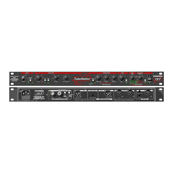
Tube Station 1 OPERATORS’ MANUAL DRAWMER Tube Station 1 Stereo Vacuum Tube Compressor with Instrument & Mic Pre SAFETY CONSIDERATIONS CAUTION - MAINS FUSE TO REDUCE THE RISK OF FIRE REPLACE THE MAINS FUSE ONLY WITH THE SAME TYPE, WHICH MUST BE A CLASS 3, 250 VOLT, TIME DELAY TYPE, RATED AT 160mA WHERE THE MAINS INPUT IS SET TO 230 VOLTS AC. -
Page 4: Introduction
In addition the rack should be fan cooled, with air blowing onto the TS1, this will extend the life and reliability of the units. Avoid mounting the unit directly above power amplifiers or power supplies that radiate significant amounts of heat and always connect the mains earth to the unit. -
Page 5: Power Connection
Tube Station 1 OPERATORS’ MANUAL POWER CONNECTION If the unit is required to operate at a mains input voltage which is different to that supplied: The following procedure must be carried out by a qualified technical engineer. Disconnect the unit from the mains. Remove the twelve screws that retain the top cover. -
Page 6: Digital Module
Tube Station 1 OPERATORS’ MANUAL DIGITAL MODULE INSTALLATION The Digital modules are designed only for operation within a Drawmer Tube Station. Under NO circumstances should the module be installed into any other manufacturers’ or custom device. Full anti static handling precautions must be followed to prevent damage to sensitive circuitry. -
Page 7: Control Descriptions
Tube Station 1 OPERATORS’ MANUAL CONTROL DESCRIPTION INPUT and FRONT END SECTION Pre-Amp Input Selects the Instrument input ................Gain Adjusts the Mic Gain over a range of 0dB to 60dB. -
Page 8: Compressor Section
Tube Station 1 OPERATORS’ MANUAL COMPRESSOR SECTION Source Selects between the Line Input and the Front End Section. Compressor This serves as the input gain control to the compressor which has a preset threshold. Rotate clockwise until the required amount of compression is achieved. -
Page 9: Analogue
Two eight-section LED meters display the signal level (from !35dB to 0dB) sent to the Digital Output (if fitted). Analogue Output Sets the overall Analogue output level of the TS1 from Off to +16dB. Adjusting this control does not change the meter levels. Bypass Switches the unit into Bypass to allow comparison with the input signal, illuminates the status LED. -
Page 10: Digital
Tube Station 1 OPERATORS’ MANUAL DIGITAL OUTPUT - OPTIONAL EXT CLOCK Auto detects whether a valid external clock is connected to the unit. A Led lights to indicate that the signal has locked. SPDIF Via a high quality RCA type phono jack where the data conforms to the Sony™... -
Page 11: Operation
Tube Station 1 OPERATORS’ MANUAL... - Page 12 Tube Station 1 OPERATORS’ MANUAL...
- Page 13 Tube Station 1 OPERATORS’ MANUAL...
-
Page 14: If A Fault Develops
Drawmer Electronics Ltd., will be pleased to answer all application questions to enhance your usage of this equipment. Please address correspondence to: Drawmer (Technical Help line) : Coleman St. : Parkgate : Rotherham : S62 6EL : UK or, E-mail us on : tech@drawmer.com... -
Page 15: Technical Specification
Tube Station 1 OPERATORS’ MANUAL TECHNICAL SPECIFICATIONS (Measurements taken using +4dBu balanced input where applicable) ANALOGUE INPUT IMPEDANCE - LINE 20KS (bal) - INSTR MAXIMUM INPUT LEVEL +21dBu LINE INPUT CMR Better than !40dB (20Hz - 22KHz) MIC INPUT NOISE !130dB @ +60dB gain with 150S load (ref 0dBu) OUTPUT IMPEDANCE 100S... -
Page 16: Block Diagram
Tube Station 1 OPERATORS’ MANUAL BLOCK DIAGRAM...
Need help?
Do you have a question about the TS1 and is the answer not in the manual?
Questions and answers