Table of Contents
Advertisement
Quick Links
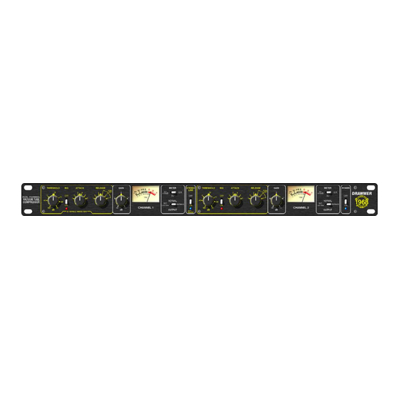
DRAWMER
Vacuum Tube Compressor
. . . . . . . . . . . . . . . . . . . . . . . . . . . . . . . . . . . . . . . . . . . . . . . . . . . . . . . . . . . 2
Chapter 1 - Introduction
. . . . . . . . . . . . . . . . . . . . . . . . . . . . . . . . . . . . . . . . . . . . . . . . . . . . . . . 3
. . . . . . . . . . . . . . . . . . . . . . . . . . . . . . . . . . . . . . . . . . . . . . . . . . . . . . . . 4
Chapter 2 - Control Description
. . . . . . . . . . . . . . . . . . . . . . . . . . . . . . . . . . . . . . . . . . . . . . . . . . . 8
. . . . . . . . . . . . . . . . . . . . . . . . . . . . . . . . . . . . . . . . . . . . . . . . . . . . 9
Dual Channel
OPERATOR'S MANUAL
CONTENTS
. . . . . . . . . . . . . . . . . . . . . . . . . . . . . . . . . . . . . . . . . . . . . . . . 2
. . . . . . . . . . . . . . . . . . . . . . . . . . . . . . . . . . . . . . . . . . . . . . . . . 4
. . . . . . . . . . . . . . . . . . . . . . . . . . . . . . . . . . . . . . . . . . . . . . . . . 5
. . . . . . . . . . . . . . . . . . . . . . . . . . . . . . . . . . . . . . . . . . . . . . . . . 6
. . . . . . . . . . . . . . . . . . . . . . . . . . . . . . . . . . . . . . . . . 7
. . . . . . . . . . . . . . . . . . . . . . . . . . . . . . . . . . . . . . . . . . . . . . . . 8
Advertisement
Table of Contents

Related Manuals for Drawmer dl221


Summary of Contents for Drawmer dl221
-
Page 1: Table Of Contents
........... 8 Contacting Drawmer . -
Page 2: Warranty
COPYRIGHT This manual is copyrighted c 2004 by Drawmer Electronics Ltd. With all rights reserved. Under copyright laws, no part of this publication may be reproduced, transmitted, stored in a retrieval system or translated into any language in any form by any means, mechanical, optical, electronic, recording, or otherwise, with- out the written permission of Drawmer Electronics Ltd. -
Page 3: Introduction
Featured on both channels is a switchable ‘BIG’ mode which applies less processing to the fundamental low The original Drawmer 1960 used a tube stage at the front frequency but still disciplines the upward associated of the compressor, whilst the 1968 utilisies a J-FET (Field harmonics which if untamed can result in a ‘boomy’... -
Page 4: Installation
This would allow the user to insert additional EQ for some de-essing, or frequency conscious compression. The side-chain access point is unbalanced, connection is via stereo 3" jacks, the wiring convention being: ring is signal send, tip is signal return and sleeve ground. DRAWMER 1968 O PERATOR’S ANUA... -
Page 5: Power Connection
4b: Exchange the 315mA fuse below the mains socket for a similar type rated at 160mA Fuse In both cases: 5: Replace the top cover using the seven screws. 6: Re-connect to mains power source. fig.3 The Location of the Fuse DRAWMER 1968 O PERATOR’S ANUA... -
Page 6: Control Description
Release Times 100 ms (Fixed) 500 msec (Fixed) 1 sec (Fixed) Semi-Auto 200 ms to 2 sec Signal dependent Semi-Auto 500 ms to 5 sec signal dependent Automatic 1 sec to 10 sec signal dependent DRAWMER 1968 O PERATOR’S ANUA... -
Page 7: The Quick Setup Procedure
• Use the Output Gain control to restore any level lost due to compression. • If necessary, change the Attack and Release settings to suit the material. DRAWMER 1968 O PERATOR’S ANUA... -
Page 8: Chapter 3 - General Information
CHAPTER 3 GENERAL INFORMATION It is the responsibility of the installer to ensure that the continuous power rating of the speakers is not exceeded, as Drawmer Electronics Ltd will not accept any responsibitlity for speaker damage caused by incorrect settings. -
Page 9: Block Diagram
BLOCK DIAGRAM 1968 ver 01 A 05/05/04 DRAWMER 1968 O PERATOR’S ANUA...
Need help?
Do you have a question about the dl221 and is the answer not in the manual?
Questions and answers